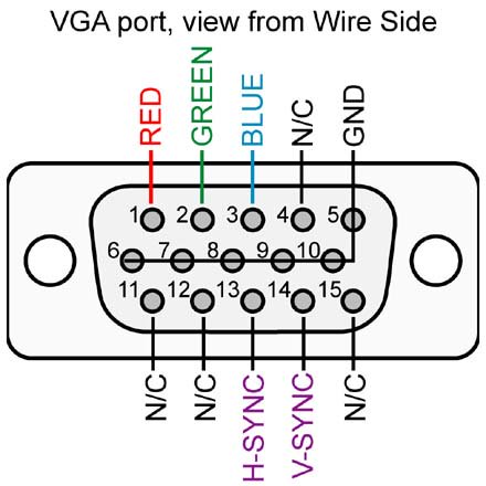
So, I could not sleep until I got this relay wired and working lol. I probably should have researched this a bit more first but the standard run of the mill VGA cable 1. does not use all pins and 2. several pins are tied together.
I did some searching and they do make HD-15 cables that use all wires and are straight through. Just a quick search on amazon and the cables seem a bit pricey but they have them.
https://www.amazon.com/Amphenol-CS-...id=1543328683&sr=8-4&keywords=dsub+hd15+cable
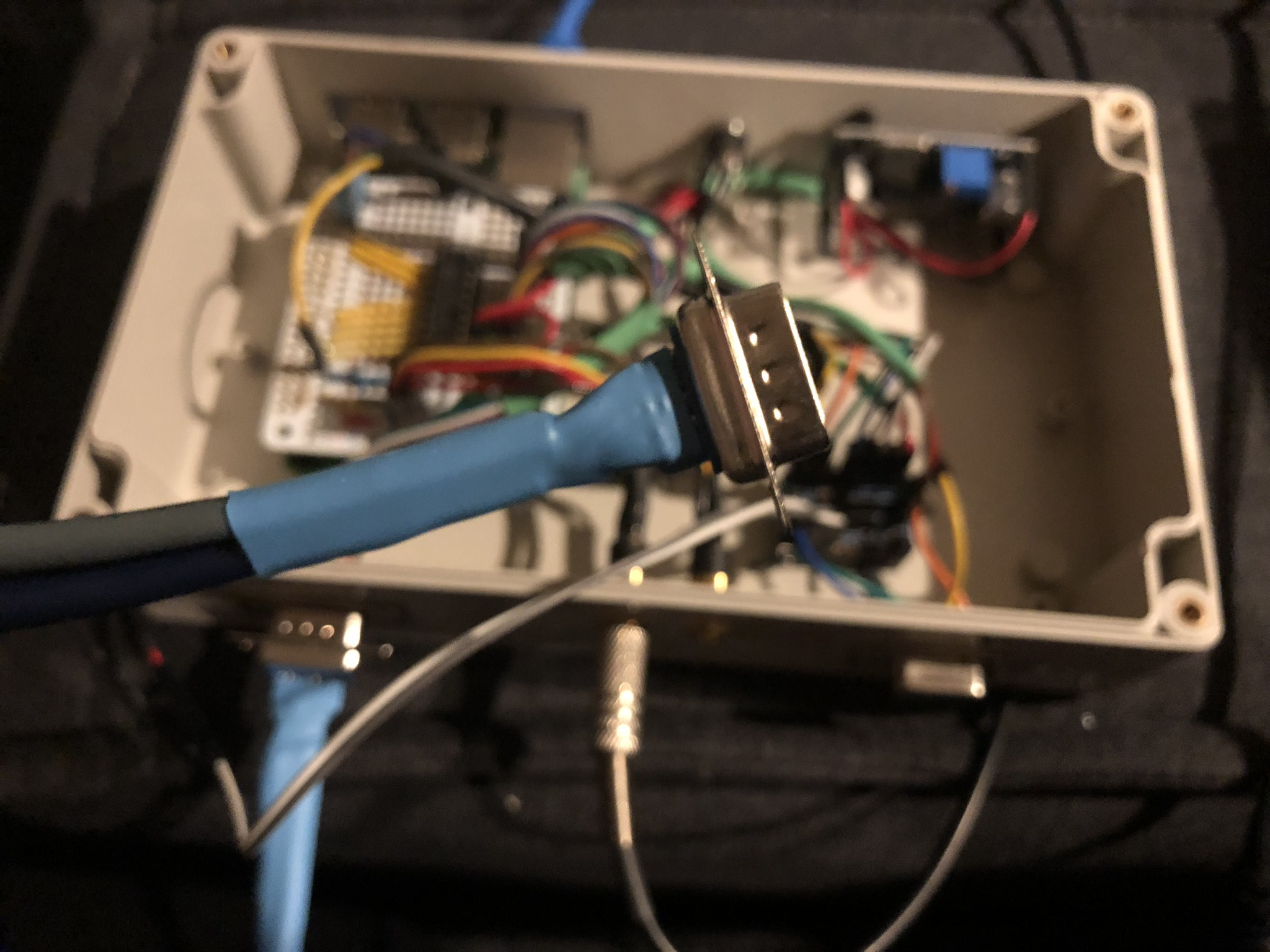
But I was on a mission lol. I wanted to get the relay hooked up and tested so I improvised. When I ordered the DSUB connectors it was the same price for one as it was for several so I have a tone of male and female connectors. I dug back into my junk box and pulled out 2 cat 5 cables and made myself a makeshift cable that will work for now until I can get a proper one. I soldered it all together and forgot that I have to reverse the wiring on the other side so had to remove and re do it, in the end its not pretty but does the job for now.
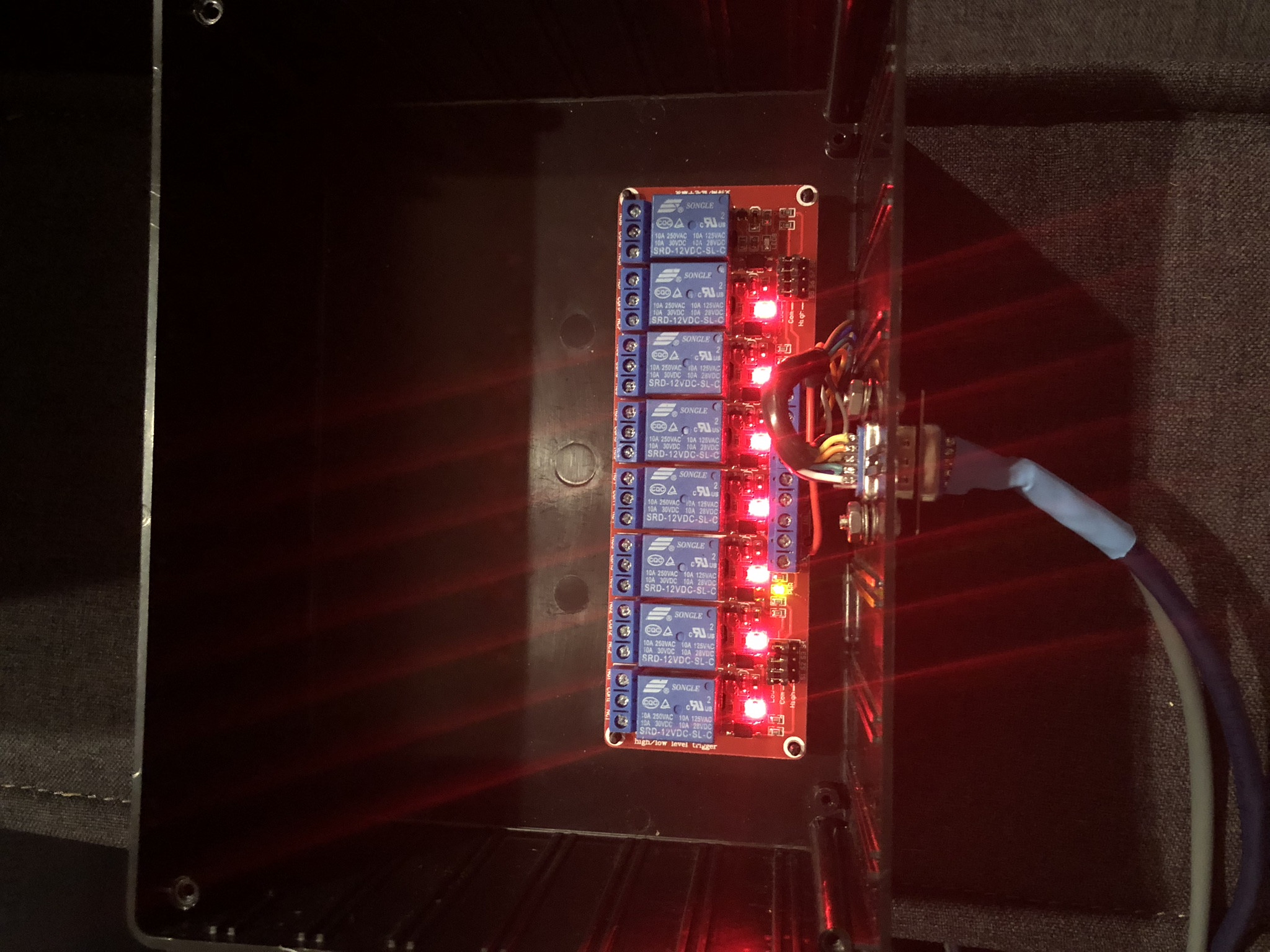
The relay I picked up is pretty cool. I dont know if it matters or not but it makes sense in my mind lol I wanted to keep as many peripherals off the 5 volt rail that supplies the RPI to reduce any chance of interference. I have the main 12 volt supply that branches to the LM2956 to step down the voltage to 5 volts for the RPI and all other 12 volt requirements for the relays, motor drivers, doser motors, etc all come directly off the main 12 volt input. To avoid getting another LM2956 to step down to 5 volts again I sourced a 12 volt relay and its pretty slick. I still have to take a step back and remember we are dealing with digital electronics 1's and 0's not so much power and ground. This relay did not come with any instructions but has jumpers for high and low input. My analog mind was thinking low was 3.3v and high was 12 volts or something along those lines. But the high and low represents high as in 1 and low as in 0, or in analog terms high=voltage low=ground. The GPIO pins off the RPI run high which is 3.3v or a 1. If you connect the positive end of an LED to the GPIO pin and the other to ground you can light it on and off with the software. But to protect the pi from over current we isolate it by triggering the input pin of a ULN2803 driver which provides a higher current capable output. The catch is that the output is reversed so that when the GPIO pin is triggered the ULN2803 output is biased towards 0 or ground instead. So now to light an LED the positive lead goes to the power source and the ground lead goes to the output of the ULN2803. When the GPIO pin is triggered it grounds the LED and it lights up. So the BLUF is this relay
https://www.amazon.com/gp/product/B00LW2GA5Y/ref=oh_aui_detailpage_o00_s00?ie=UTF8&psc=1 can accept both a positive or negative input. Since we are outputting negative 0 the jumpers get set to low.
So I have one cable running to my power box. It supplies 12 volts and all the GPIO pins to the relays. Its not as fancy as the DJ power strip but it works :) Next up is wiring the outlets.
I believe it was
@Erica-Renee in the mega thread that brought this up and it was such a good idea that I scrapped the idea of using the DJ power strip and started looking at building my own power strip. Now that my relays are active I can see where there is a potentially big issue if reef-pi or the the RPI unexpectedly quits. As soon as power is pulled from the RPI all the relays shut off. If you are running multiple things that typically run all the time and you are away for a week this could be a big problem till you get back and get hands on to find the problem. If the pi where to quit I would want the following:
Heater: off
Return: on
Skimmer: on
ATO: off
Sump light: on
At least one circulation pump: on
So a relay has two states Normally Open (NO) and Normally Closed (NC)
The GPIO output and either ground or power is applied to the coil side which pulls it to NO and when the GPIO signal is removed it goes back to NC. Most of the relay outputs have 3 pins NC, Common, and NO. Common is the power source you wish to switch and you have to determine if you want power output when the relay is off or power output when the relay is triggered. Since I want several outputs to remain with power if communication or power to the pi is lost I will be wiring half the power outlets to the NC and half to the NO. More on this once I get to that portion.