SuncrestReef
That Apex guy
View BadgesExcellence Award
Reef Tank 365
Article Contributor
Reef Squad Emeritus
Controller Advisor
The Neptune Apex consists of many components, whether you have the most basic Apex setup or an extensive collection of add-on modules. One of the challenges in configuring and managing your Apex is the process of identifying each of the Inputs, Outputs, and Modules connected to the Apex. But the System View in Fusion can greatly simplify the process of identifying which Input and Output is associated with individual Modules or on the Apex base unit itself.
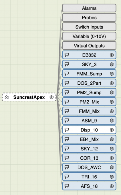
The System View was first introduced in a Fusion update on May 3, 2019, and then also added to the Apex Local interface with the release of AOS 5.05_5B19 on May 13, 2019.
Note: The Apex.Local System View is only available for the current model Apex 2016 and Apex-EL, but the System View is available through Fusion for all models of Apex, with limitations on the Apex Classic and older models. These limitations will be noted below.
You can access the System View from the Fusion Dashboard in two ways:
1. Click the gear icon to expand the icon menu, then click the System View icon.

- or -
2. Click the Apex menu, then select System from the list of menu items below the Configuration heading.

The System View is a tree-style representation of your Apex system. The tree can be expanded and collapsed to show more or less detail as you click on each item. Each item in the tree is color-coded to identify the type of each item.
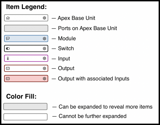
Any item that has a shaded background indicates that item contains additional items, and clicking the shaded item will expand it to show the associated items it contains. For example, the FMM Module contains one output (the 24v Accessory port), and 4 ports which can either be Switches (for optical sensors and leak sensors) or Inputs (for flow monitors).
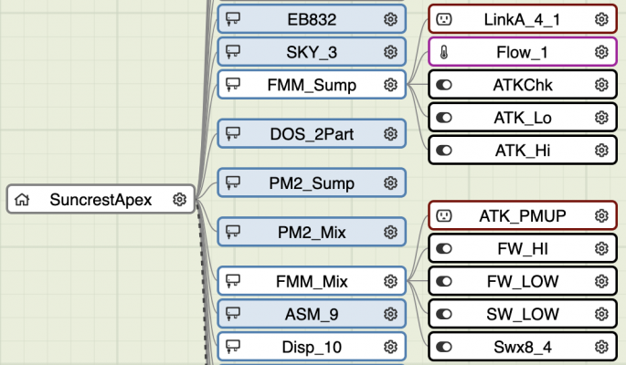
So why is this System View so important, and why am I writing a tutorial about it? As I frequently answer Apex questions here on R2R, the Neptune Community Forum, and the Neptune Facebook group, it’s amazing how many times the root cause of the problems is that the Apex user is programming the wrong output or referencing the name of the wrong input in their programming, and can’t understand why it’s not working the way they expected. The System View can help you identify the correct names of Inputs and Outputs associated with the module they are connected to. This becomes more and more important as you connect additional modules to your Apex, which increases the number of inputs and outputs.
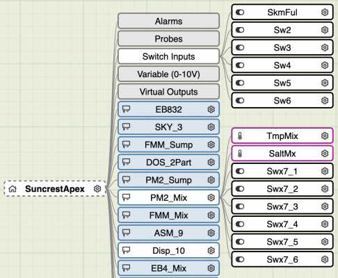
Here’s an example: If you have a breakout box (BOB) and you want to connect a float switch to detect the water level in your sump, the default name of that switch is going to depend on which port on the breakout box you connect it to, but it also depends on where the breakout box itself is plugged in. The breakout box can connect to the round 8-pin DIN connector on the Apex base unit, or the same connector on the PM1, PM2, PM3, or ASM modules as listed in my Apex Hardware Overview article. Since every input on the Apex system requires a unique name, and those names have defaults which are automatically assigned unless you manually rename them, it’s easy to accidentally assume the wrong name in your programming. The default names for the 6 BOB switches on the Apex base unit are:
This can also be confusing when you’re trying to add a tile to your Fusion dashboard. When you click the padlock icon to unlock the dashboard and reveal the Unused Tiles window at the top of the screen, you’ll see the names of every single Input and Output available. These names show up even if nothing is plugged in, so the list can be long to scroll through.

Here’s where the System View comes in very handy. In addition to viewing each Module and the corresponding Inputs and Outputs, you can click the gear icon on each item to quickly jump to the configuration screen where you can rename them. So for the float switch connected to the breakout box connected to the Apex base unit, just click the “Switch Inputs” node of the Apex base unit, then click the gear icon for the specific switch number where you connected the float switch. On the Configuration screen, edit the name to be more meaningful than the Sw# name, save the changes by clicking the orange cloud icon at the top of the screen, then you can use that new name in your programming or click and drag that named tile onto your dashboard from the Unused Tiles window.

NOTE: The Apex Classic and older models do not support renaming Inputs or Modules from the System View screen. You need to use the Classic Dashboard to rename and configure Modules and Inputs.
I highly recommend renaming every Input and Output where you have a device in use so the names are relevant and obvious as you are programming and managing your Apex. It’s fine to leave the unused items with the default names. But be aware…you should never have any duplicate names anywhere in your Apex configuration. For example, if you decide to rename all of the unused outputs on your EnergyBar, don’t name them all “Unused”. Duplicate names can cause the Apex to malfunction in unexpected ways. It’s better to name them “Unused6”, “Unused7”, “Unused8”, etc.
Also remember the naming length limitations:
The System View will appear differently depending on the model of Apex you are managing. The full Apex 2016 model will show its Alarms, Probes, Switch Inputs, and 0-10v Variable outputs:

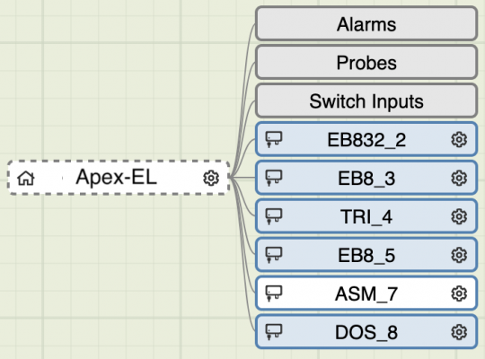
The Apex-EL will only show its Alarms, Probes, and Switch Inputs, since it does not have any built-in 24v Variable outputs:
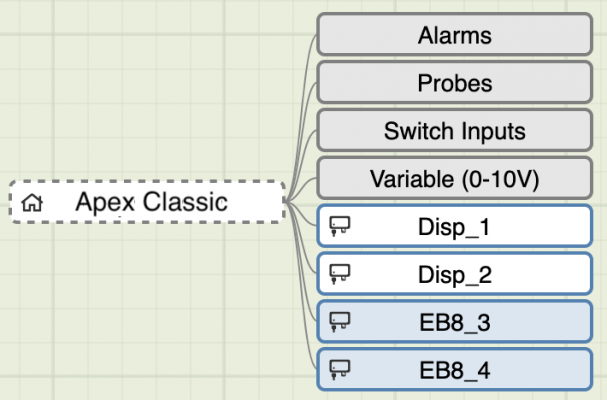
The Apex Classic and older models will show the relevant items, but notice there is no gear icon on the Modules or Inputs since those items must be managed separately in the Classic Dashboard interface rather than through Fusion:
Each type of module will display its corresponding Inputs and outputs. As mentioned above, the FMM will display each port depending on how it’s configured. It can have switches for the optical sensors and leak sensors, or it can have Inputs for flow sensors.

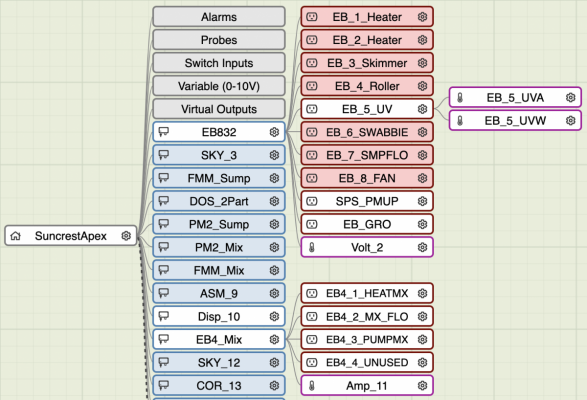
The EnergyBar nodes will appear differently depending on the model. The EB832 (and new EB632) will show shaded nodes for each Output since those outputs support power monitoring, with corresponding Amps and Watts Inputs for each Output. The older EB4, EB6, and EB8 only have a single Input for the whole module reporting the overall amps utilized.
Another useful feature of the System View is the ability to quickly see the details of any selected item. When you click an item, its outline turns to an animated dashed line. While that item is the active selection, you can click the down arrow icon at the upper right to reveal the details of that item which includes the Type, Device number, and Description.

Another miscellaneous feature is that the whole tree view can be zoomed in and out, by either pinching and zooming, or Control-click and drag, depending on the device you are using. This will allow you to see your entire configuration in a single view if you zoom out far enough. You can also zoom in, then click and drag to scroll the tree view into place within the window.
Hopefully, this tutorial will give you more insight into all the components of your Apex system, and help you avoid the common mistake of referencing the incorrect names of devices in your programming.
Be sure to check out the other topics in my Apex Tutorial series here on Reef2Reef:

 www.reef2reef.com

The System View was first introduced in a Fusion update on May 3, 2019, and then also added to the Apex Local interface with the release of AOS 5.05_5B19 on May 13, 2019.
Note: The Apex.Local System View is only available for the current model Apex 2016 and Apex-EL, but the System View is available through Fusion for all models of Apex, with limitations on the Apex Classic and older models. These limitations will be noted below.
You can access the System View from the Fusion Dashboard in two ways:
1. Click the gear icon to expand the icon menu, then click the System View icon.

- or -
2. Click the Apex menu, then select System from the list of menu items below the Configuration heading.

The System View is a tree-style representation of your Apex system. The tree can be expanded and collapsed to show more or less detail as you click on each item. Each item in the tree is color-coded to identify the type of each item.
- Apex
- Base Unit Ports
- Modules
- Inputs
- Outputs

Any item that has a shaded background indicates that item contains additional items, and clicking the shaded item will expand it to show the associated items it contains. For example, the FMM Module contains one output (the 24v Accessory port), and 4 ports which can either be Switches (for optical sensors and leak sensors) or Inputs (for flow monitors).

So why is this System View so important, and why am I writing a tutorial about it? As I frequently answer Apex questions here on R2R, the Neptune Community Forum, and the Neptune Facebook group, it’s amazing how many times the root cause of the problems is that the Apex user is programming the wrong output or referencing the name of the wrong input in their programming, and can’t understand why it’s not working the way they expected. The System View can help you identify the correct names of Inputs and Outputs associated with the module they are connected to. This becomes more and more important as you connect additional modules to your Apex, which increases the number of inputs and outputs.
Here’s an example: If you have a breakout box (BOB) and you want to connect a float switch to detect the water level in your sump, the default name of that switch is going to depend on which port on the breakout box you connect it to, but it also depends on where the breakout box itself is plugged in. The breakout box can connect to the round 8-pin DIN connector on the Apex base unit, or the same connector on the PM1, PM2, PM3, or ASM modules as listed in my Apex Hardware Overview article. Since every input on the Apex system requires a unique name, and those names have defaults which are automatically assigned unless you manually rename them, it’s easy to accidentally assume the wrong name in your programming. The default names for the 6 BOB switches on the Apex base unit are:
- Sw1
- Sw2
- Sw3
- Sw4
- Sw5
- Sw6
- Swx7_1
- Swx7_2
- Swx7_3
- Swx7_4
- Swx7_5
- Swx7_6

This can also be confusing when you’re trying to add a tile to your Fusion dashboard. When you click the padlock icon to unlock the dashboard and reveal the Unused Tiles window at the top of the screen, you’ll see the names of every single Input and Output available. These names show up even if nothing is plugged in, so the list can be long to scroll through.
Here’s where the System View comes in very handy. In addition to viewing each Module and the corresponding Inputs and Outputs, you can click the gear icon on each item to quickly jump to the configuration screen where you can rename them. So for the float switch connected to the breakout box connected to the Apex base unit, just click the “Switch Inputs” node of the Apex base unit, then click the gear icon for the specific switch number where you connected the float switch. On the Configuration screen, edit the name to be more meaningful than the Sw# name, save the changes by clicking the orange cloud icon at the top of the screen, then you can use that new name in your programming or click and drag that named tile onto your dashboard from the Unused Tiles window.
NOTE: The Apex Classic and older models do not support renaming Inputs or Modules from the System View screen. You need to use the Classic Dashboard to rename and configure Modules and Inputs.
I highly recommend renaming every Input and Output where you have a device in use so the names are relevant and obvious as you are programming and managing your Apex. It’s fine to leave the unused items with the default names. But be aware…you should never have any duplicate names anywhere in your Apex configuration. For example, if you decide to rename all of the unused outputs on your EnergyBar, don’t name them all “Unused”. Duplicate names can cause the Apex to malfunction in unexpected ways. It’s better to name them “Unused6”, “Unused7”, “Unused8”, etc.
Also remember the naming length limitations:
- Modules = 11 characters
- Outputs = 12 characters
- Inputs = 6 characters
- Profiles = 11 characters
The System View will appear differently depending on the model of Apex you are managing. The full Apex 2016 model will show its Alarms, Probes, Switch Inputs, and 0-10v Variable outputs:

The Apex-EL will only show its Alarms, Probes, and Switch Inputs, since it does not have any built-in 24v Variable outputs:

The Apex Classic and older models will show the relevant items, but notice there is no gear icon on the Modules or Inputs since those items must be managed separately in the Classic Dashboard interface rather than through Fusion:

Each type of module will display its corresponding Inputs and outputs. As mentioned above, the FMM will display each port depending on how it’s configured. It can have switches for the optical sensors and leak sensors, or it can have Inputs for flow sensors.

The EnergyBar nodes will appear differently depending on the model. The EB832 (and new EB632) will show shaded nodes for each Output since those outputs support power monitoring, with corresponding Amps and Watts Inputs for each Output. The older EB4, EB6, and EB8 only have a single Input for the whole module reporting the overall amps utilized.

Another useful feature of the System View is the ability to quickly see the details of any selected item. When you click an item, its outline turns to an animated dashed line. While that item is the active selection, you can click the down arrow icon at the upper right to reveal the details of that item which includes the Type, Device number, and Description.
Another miscellaneous feature is that the whole tree view can be zoomed in and out, by either pinching and zooming, or Control-click and drag, depending on the device you are using. This will allow you to see your entire configuration in a single view if you zoom out far enough. You can also zoom in, then click and drag to scroll the tree view into place within the window.
Hopefully, this tutorial will give you more insight into all the components of your Apex system, and help you avoid the common mistake of referencing the incorrect names of devices in your programming.
Be sure to check out the other topics in my Apex Tutorial series here on Reef2Reef:

Articles by SuncrestReef
 www.reef2reef.com
Last edited by a moderator:


