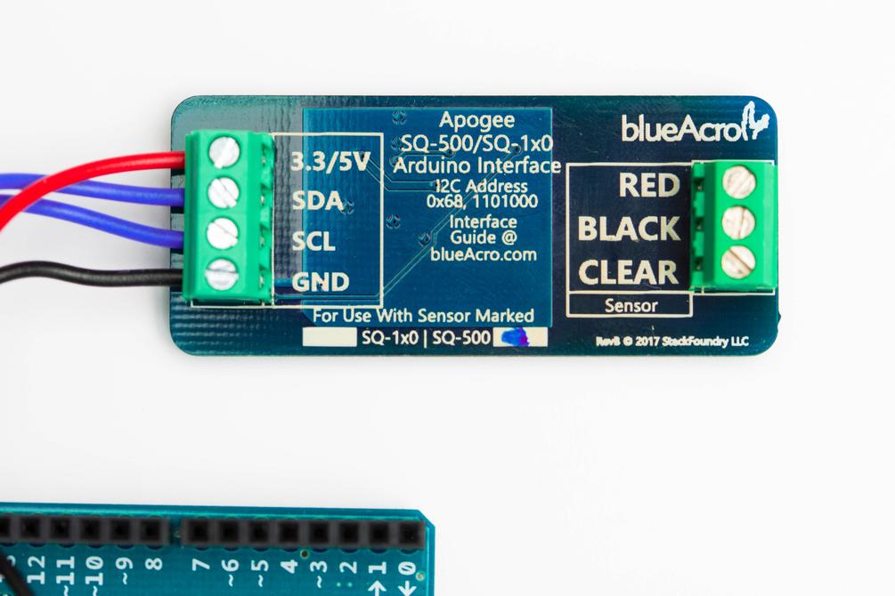
Has anyone here used the Arduino SQ-500 PAR sensor interface from blueacro? I thought the price was a bit steep ($37 shipped) for what it is, but bought it anyway to save time on my PAR meter project. Ordered it Monday but it hasn't shipped yet. I don't see any sort of documentation for it on the website either.

Navigation
Install the app
How to install the app on iOS
Follow along with the video below to see how to install our site as a web app on your home screen.
Note: This feature may not be available in some browsers.
More options
You are using an out of date browser. It may not display this or other websites correctly.
You should upgrade or use an alternative browser.
You should upgrade or use an alternative browser.
BlueAcro SQ-500 PAR sensor Arduino interface
- Thread starter ClownWrangler
- Start date
- Tagged users None


SPR1968
No, it wasn’t expensive dear....
View Badges
Reef Squad
Reef Squad Leader
Excellence Award
Reef Tank 365
UK Reef Club Member
Hospitality Award
I can’t answer the specific question, but I can bump the thread to see if we can get you some help
- Joined
- Sep 18, 2017
- Messages
- 5,585
- Reaction score
- 3,438
Hmmmm what question do you have?Has anyone here used the Arduino SQ-500 PAR sensor interface from blueacro? I thought the price was a bit steep ($37 shipped) for what it is, but bought it anyway to save time on my PAR meter project. Ordered it Monday but it hasn't shipped yet. I don't see any sort of documentation for it on the website either.
Sensor wires are color coded.
One lithium coin cell needed (2032) to run the amplifier.
Plugs directly in the VOM banana jack ports.
Labelled as to which.
My meter is set to 200mV range and obviously a different sensor (way more than .01mV per 1 PAR but for example).
.01 x 100 = 1mV = 1 "par"0.01 mV per μmol m⁻² s⁻
131 mV = 131 "par"
Simply plug in the Amplifier to your multi-meter, connect the sensor to the terminal block, turn on the amplifier, and switch your multimeter to the 2V or millivolt range to read PAR on the display. If you are using the 2V range, simply ignore the decimal point.
Amplifies 10uV (microvolt) signals to milli-volt signals (100x gain)
.

OP
OP
Hmmmm what question do you have?
Sensor wires are color coded.
One lithium coin cell needed (2032) to run the amplifier.
Plugs directly in the VOM banana jack ports.
Labelled as to which.
My meter is set to 200mV range and obviously a different sensor (way more than .01mV per 1 PAR but for example).
.01 x 100 = 1mV = 1 "par"
131 mV = 131 "par"
.
I got the Arduino interface version. I sent an email today and got a shipping notice, but no info on the coding for the I2C interface. Ill just have to wait until I get it, ID the Chip and find a datasheet for the ADC. I was having trouble deciding on the version you have or the later and decided on the ADC version so I could make a dedicated meter and data logger. Also, with the version you have, you need to multiply the reading by the correction factor for under water measurements manually, which could get tedious.
https://www.apogeeinstruments.com/underwater-par-measurements/
You need to multiply your meter measurements by either 1.25 or 1.32 for imersion effect depending on the SN of your sensor. See page 16:
https://www.apogeeinstruments.com/content/SQ-500.pdf
Last edited:
OP
OP
Sorry. My fault. I didn't specify which interface in my original post. So, do I just send an email to that address asking for the interface guide?

- Joined
- Sep 18, 2017
- Messages
- 5,585
- Reaction score
- 3,438
That would be my guess. Kind of err " unusual" but ????Sorry. My fault. I didn't specify which interface in my original post. So, do I just send an email to that address asking for the interface guide?
That address was silkscreened on the board in the picture.
That would be my guess. Kind of err " unusual" but ????
That address was silkscreened on the board in the picture.
Welp thats my bad.
The clearest example is the sample Arduino sketch:
apogee_sq500/sq500_i2c.ino at master · blueacro/apogee_sq500
Example Sketch for Reading SQ500 Sensor. Contribute to blueacro/apogee_sq500 development by creating an account on GitHub.
 github.com
OP
OP
Welp thats my bad.
The clearest example is the sample Arduino sketch:
apogee_sq500/sq500_i2c.ino at master · blueacro/apogee_sq500
Example Sketch for Reading SQ500 Sensor. Contribute to blueacro/apogee_sq500 development by creating an account on GitHub.
Thank you. The code threw me off at first because my brain was in MATLAB mode with functions being at the end of the scrip. Lol. I see what's going on with it for the most part with the I2C library and main loop, but what's going on with the communications to the device is a bit esoteric without comments in the code. Some comments would make it bit more useful as an interface guide.

Thank you. The code threw me off at first because my brain was in MATLAB mode with functions being at the end of the scrip. Lol. I see what's going on with it for the most part with the I2C library and main loop, but what's going on with the communications to the device is a bit esoteric without comments in the code. Some comments would make it bit more useful as an interface guide.
Point noted - this was a very early product and it hasn’t kept as much care and feeding
")
The brains of the adapter are a MCP3425, so all of the I2C setup is mode setting the ADC:
OP
OP
Point noted - this was a very early product and it hasn’t kept as much care and feeding
The brains of the adapter are a MCP3425, so all of the I2C setup is mode setting the ADC:
Thank you. I ordered the Arduino interface version but was on the fence about the analog version because I'd like to be able to see how much ripple makes it through the sensor and amplifier section of the circuit with PWM dimmed lighting. I'm presuming a low pass filter is incorporated. Is this something you have analyzed? Is it a non issue for sampling in terms of aliasing, sample rate ect?
OP
OP
Just an update. I put this project to the side because I got busy with other things. Got it working easily with the code provided and my own code for the interface/display. I used an Atmega 168P board at 8mhz and 3.3v due to its low power consumption and low cost. The SSD1306 OLED display libraries took over half the memory, but the rest of the code is lite. I'm surprised how easy the OLED display is to read given its small size. I still have some coding to do for added functionality. Right now I can select between air and water measurements with the appropriate correction factor applied. I may add some additional code for averaging values for "shimmer" effect, storing measurements, correction factor table from the user guide ect.
I like the convenience of the blueAcro instrumentation amplifier/ADC board, but I think its design could be improved by reducing its footprint to that of an Arduino Nano Pro board and including standard 2.54mm pin header holes in place of the screw terminals. I will likely remove those to fit it in the packaging along with the two CR2032 batteries.

I like the convenience of the blueAcro instrumentation amplifier/ADC board, but I think its design could be improved by reducing its footprint to that of an Arduino Nano Pro board and including standard 2.54mm pin header holes in place of the screw terminals. I will likely remove those to fit it in the packaging along with the two CR2032 batteries.
Last edited:

Just an update. I put this project to the side because I got busy with other things. Got it working easily with the code provided and my own code for the interface/display. I used an Atmega 168P board at 8mhz and 3.3v due to its low power consumption and low cost. The SSD1306 OLED display libraries took over half the memory, but the rest of the code is lite. I'm surprised how easy the OLED display is to read given its small size. I still have some coding to do for added functionality. Right now I can select between air and water measurements with the appropriate correction factor applied. I may add some additional code for averaging values for "shimmer" effect, storing measurements, correction factor table from the user guide ect.
I like the convenience of the blueAcro instrumentation amplifier/ADC board, but I think its design could be improved by reducing its footprint to that of an Arduino Nano Pro board and including standard 2.54mm pin header holes in place of the screw terminals. I will likely remove those to fit it in the packaging along with the two CR2032 batteries.
Thanks for the feedback! I agree pin headers probably make more sense for prototypes.
I may spin an alternate version of this for some Reef-Pi USB integration as well.
Similar threads
- Replies
- 27
- Views
- 612
- Replies
- 3
- Views
- 206
- Replies
- 1
- Views
- 263
California Aquarium Controller Lighting Drygoods
new in box Neptune PMK - Par Metering Kit - Bay Area 95121
- Price: 220
- Shipping Available
- Replies
- 2
- Views
- 428