Coffee Maker ATO (power source)

Good idea or bad idea?

  • Bad idea

  • Good idea

  • Could go either way


Results are only viewable after voting.

Hermie

Valuable Member
View Badges
Joined
Oct 25, 2018
Messages
2,444
Reaction score
2,613
Location
Georgia OTP
Rating - 0%
0   0   0
I've seen the many great ATO posts already made, so I am trying to keep this focused on the novelty of my build. Basically, we had a coffee maker (automatic drip) for which the coffee pot broke and ended up buying a whole new machine. Suffice it to say, I took apart the old machine and found the powersource I'll be using to drive a ~120VAC either pump or solenoid plus the 12VDC relay/sensor circuit. Turns out, the way this coffee maker works, it's just what I need for an ATO. Let me just explain my understanding of how the coffee machine works:
  1. a ~120VAC standard wall plug powers the machine
  2. this 120VAC signal powers the heating element and it powers a 12VDC circuit for the coffee machine's brain
  3. So when you plug in the coffee maker, the 12VDC circuit powers on (the clock, buttons etc.) waiting for input (from you).
  4. Press the "brew" button and the brain switches on a 12VDC relay to power the 120VAC heating element.
  5. The heating element runs at about 7 amps 115VAC which is definitely enough power to run a small pump or a solenoid (this is hundreds of watts).
Basically, what you have to do is find your coffee maker circuit board and find the VCC pin (this is the main way the board gets its power) and find the pin that when connected to the VCC, triggers the relay. On my board, this was the "Hi" pin. It's definitely not the GND pin, but if there are no markings, you could try using a multimeter to find the right pin... I can't tell you which one it is for your case. What you can do is find the Ground pin/circuit and when you press the "brew" button, one of the other circuits will get power and you'll hear the relay switch on. That's the pin you need to wire into your level sensors. Just have them control this VCC to "Hi" circuit (or whatever pin turns on the relay). The AC lines just come off of what was controlling the heating element. If there are three AC lines, like in my case, two of them go to the heating element, and when the third gets power, it prevents the heating element from turning on (IIRC, don't quote me on that though, I will try to update later).

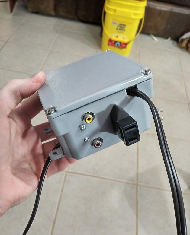
Anyways, I'll try to update this with some photos and once I have it finished. The rest of the ATO will just be based on what many people are already doing: level sensors to control the on/off signals etc. If you have any advice or tips or warnings I'll be glad to take them.

And if you are looking for a coffee maker, try a thrift store or Goodwill. They probably have some used or broken ones you can buy really cheap and take apart. Disclaimer: 120VAC can be deadly so I do not recommend anyone do this at all. I am just providing the information for theoretical purpose only.
 
Last edited:

Brad Miller

Valuable Member
View Badges
Joined
Apr 29, 2018
Messages
1,511
Reaction score
4,821
Location
Dover, Pennsylvania
Rating - 0%
0   0   0
Cool idea

If I'm understanding you correctly, you would take the dcv in series with the low level dry contact normally open float, then maybe through a high level normal closed float (to shut the Pump down if the low level float got stuck closed)

Off the top of my head, the only thing that may be a problem is that you may loose enough dcv through your wiring and switch contacts (most standard contacts are not able to pass a small amount of dcv without losing at least a little bit) that that dcv relay may not pull in since the va (volt amp) of that dcv power was sized and intended for the small wiring and run within the coffee pot.
 
OP
OP
Hermie

Hermie

Valuable Member
View Badges
Joined
Oct 25, 2018
Messages
2,444
Reaction score
2,613
Location
Georgia OTP
Rating - 0%
0   0   0
Cool idea

If I'm understanding you correctly, you would take the dcv in series with the low level dry contact normally open float, then maybe through a high level normal closed float (to shut the Pump down if the low level float got stuck closed)

Off the top of my head, the only thing that may be a problem is that you may loose enough dcv through your wiring and switch contacts (most standard contacts are not able to pass a small amount of dcv without losing at least a little bit) that that dcv relay may not pull in since the va (volt amp) of that dcv power was sized and intended for the small wiring and run within the coffee pot.

Thought about that but didn't give it serious concern, except now that you mention it... I should probably do a few tests to make sure enough power gets back to the relay...
  • Ill check how much current and voltage get passed to the "Hi" contact under normal operation
  • after adding the switches, see how much DC voltage I lose (theoretically the relay should receive the same 12Volts since it's not coming from the VCC/Hi directly)
  • see if I can lower the voltage to the "Hi" contact and see if the relay still turns on as a test
Thanks!
 
Last edited:
OP
OP
Hermie

Hermie

Valuable Member
View Badges
Joined
Oct 25, 2018
Messages
2,444
Reaction score
2,613
Location
Georgia OTP
Rating - 0%
0   0   0
So... update: I bought basically the cheapest level sensors I could find on eBay that shipped from the US (not Asia) for time sake and the first warning sign was when they arrived I checked their resistance. It was two "identical" FluidSwitch horizontal switches and they had very different resistance when switched on... I did some testing and they still seemed to work...
I got everything plugged in yesterday and when I woke up it turns out the switches get STUCK... I think they were knockoff FluidSwitch because that's a real brand and I bought cheap... My own fault. I will be finding some new horizontal fluid switches and then setting everything back up.

All in all, the electrical system all works (relay/"controller") it's just the switches now...
I bought a Home Depot carlon junction box for 7 dollars, and I am using some "coax" cables/connectors to hook the Reservoir and Sump level switches into the junction box. The reservoir pump plugs into the junction box via a standard 2 prong port, and then the power to the circuit(relay etc) just comes out via a standard 2 prong wire from the junction box.

g64vAPQ.png
 
Back
Top