I rolled it on using a foam roller. I dipped the 6 inch roller right into the can. You have to work it more than you would ordinary paint. Yes I did go up the sides about 4 inches. I used blue painters tape to create a clean line.How did the flexseal go on? Did you roll it, brush it…? Did you carry it up the sides at all?
Navigation
Install the app
How to install the app on iOS
Follow along with the video below to see how to install our site as a web app on your home screen.
Note: This feature may not be available in some browsers.
More options
You are using an out of date browser. It may not display this or other websites correctly.
You should upgrade or use an alternative browser.
You should upgrade or use an alternative browser.
Completely DIY 315 build
- Build Thread
- Thread starter bruno3047
- Start date
- Tagged users None
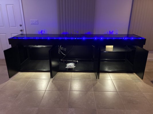
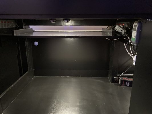
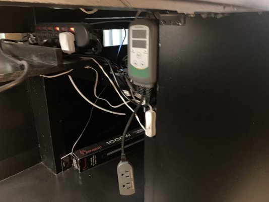
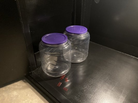
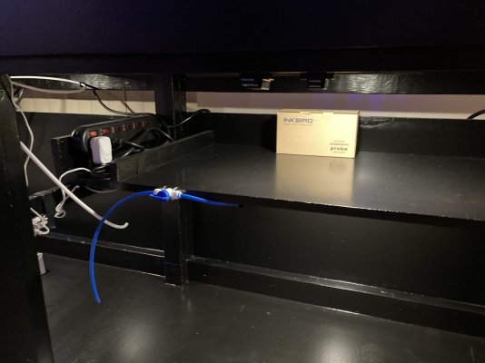
Center compartment. This is where the 40 breeder DIY trickle filter/sump will go. The filter/sump will take up the entire space. To the left, you can see a pair of 120mm waterproof case fans that will be connected to the Ink Bird temperature controller. The controller is a dual temp controller that switches the heater on when the water cools and turn the fans on when the water warms. I’m expecting to get at least 3° of cooling from this set up, based on my experience with my current tank. In the center you can see the 1000 watt titanium heater element that will go into the sump. To the right you can see the light switch for the inside cabinet lighting for the center and right compartments. Also visible is the 1/4 inch white RO tubing that is going from the final stage DI canister to the ATO reservoir.A look inside. First, left side compartment (facing tank). At the top you’ll see a 6-outlet individually switched power strip on each side protected by built-in GFCI. A removable shelf and the mounted Ink Bird temperature controller, beneath which you can see the light switch controlling the compartment LED lights, one lighting the shelf and one lighting the floor. This compartment will hold the two 29 gallon tanks, one in front of the other. The front one will be a quarantine tank the rear one will be the ATO Reservoir. The compartment will also hold the dosing pump and extra large containers to hold the CA and ALK.
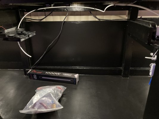
Right compartment. As with the left compartment, there is a 6-outlet individually-switched built-in GFCI power strip on each side at the top. Also visible is blue quarter-inch RO tubing coming in from the back of the stand to a valve, then out of the valve to the final stage DI canister. The tubing will be plumbed into the main house RO filter system. This is an auxiliary space that will probably hold some combination of a worm farm, mysis culture, brine shrimp culture, the DI canister, and supplies.Center compartment. This is where the 40 breeder DIY trickle filter/sump will go. The filter/sump will take up the entire space. To the left, you can see a pair of 120mm waterproof case fans that will be connected to the Ink Bird temperature controller. The controller is a dual temp controller that switches the heater on when the water cools and turn the fans on when the water warms. I’m expecting to get at least 3° of cooling from this set up, based on my experience with my current tank. In the center you can see the 1000 watt titanium heater element that will go into the sump. To the right you can see the light switch for the inside cabinet lighting for the center and right compartments. Also visible is the 1/4 inch white RO tubing that is going from the final stage DI canister to the ATO reservoir.

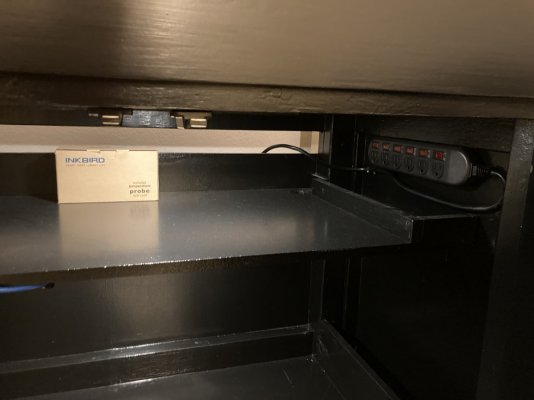
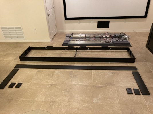
The canopy has three parts. The frame and two lighting panel assemblies. Photo of the three parts laid out on the floor.Right compartment. As with the left compartment, there is a 6-outlet individually-switched built-in GFCI power strip on each side at the top. Also visible is blue quarter-inch RO tubing coming in from the back of the stand to a valve, then out of the valve to the final stage DI canister. The tubing will be plumbed into the main house RO filter system. This is an auxiliary space that will probably hold some combination of a worm farm, mysis culture, brine shrimp culture, the DI canister, and supplies.


Last edited:
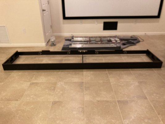
The frame was constructed using 1x4 pine material for the inner portion that was originally designed
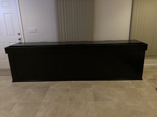
to rest directly on the aquarium glass. I have since decided that the entire assembly is too heavy for that, so I will be building a support structure for the canopy assembly, probably vertical 1x6 on each side. The fascia material is 1x6 pine smoothed out to achieve that soft finish to match the stand.
Last edited:
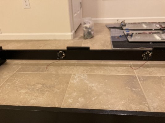
Photo showing the fan assemblies attached to the frame. There are two exhaust fans for each lighting panel.The frame was constructed using one by four pine material for the inner portion that was originally supposed to rest directly on the aquarium glass. I have since decided that the entire assembly is too heavy for that, so I will be building I support structure four the canopy assembly, probably vertical 1x6 on each side. The fascia material is 1x6 pine smoothed out to achieve that soft finish to match the stand.
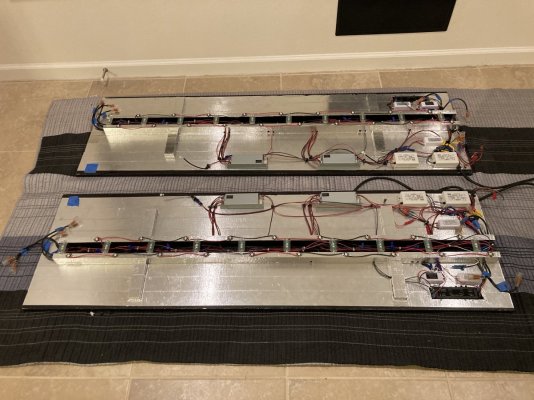
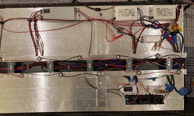
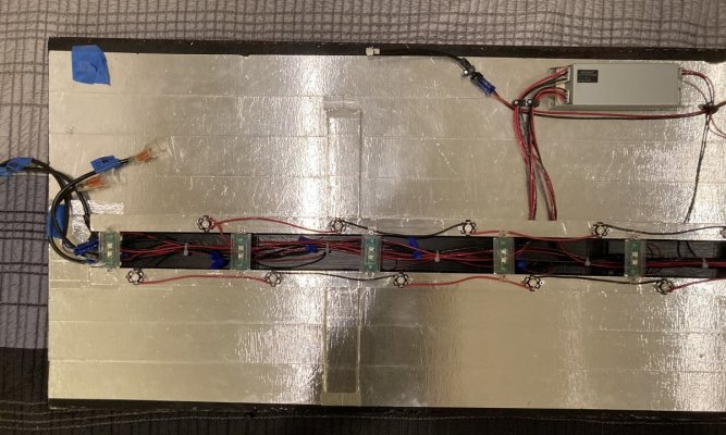
Some notes. The structure is 5/8” particleboard with two full length sections of 1x2 pine attached parallel to each other to make the center raceway channel. Two 5” lengths of 1x2 were then attached perpendicular to the channel at each end to support the individual T5 reflectors that will be installed at a later time. The entire assembly was primed with BIN123 and painted with Rustoleum protective coating flat black. The Rustoleum has a 200°F tolerance for heat. The assembly was then covered with 5.9 mil extra thick adhesive-backed HVAC aluminum tape to provide fireproofing and a heat shield. This material also provides extra heat-sinking for the LEDs.
Last edited:
More notes. Mounted on the 1x2s that make the center raceway channel are 5W Cree LEDs that are factory-mounted on printed circuit boards (PCB). The PCBs are backed with an aluminum heat sink. The heat sink will then transfer the heat to the aluminum HVAC tape. The front 1x2 is populated with Violet 425-430nm LEDS and the rear 1x2 with Royal Blue 440-450nm LEDs. These LEDs are wired in series and powered by a Meanwell constant-current LED driver at 80%. Mounted perpendicular to the 1x2s are .5W Royal Blue LEDs in a plastic case that will serve as the moonlights. These LEDs are wired in parallel and driven by a standard 6V constant-voltage LED driver.
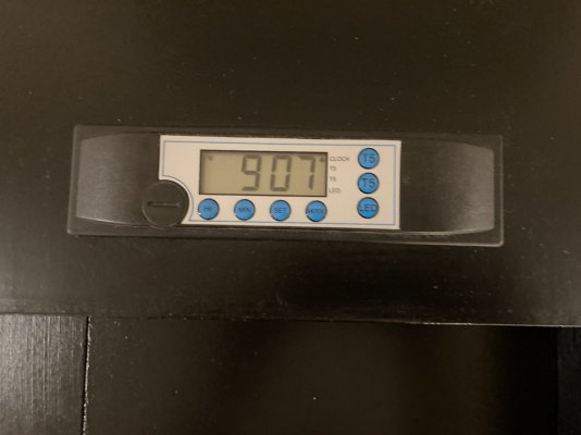
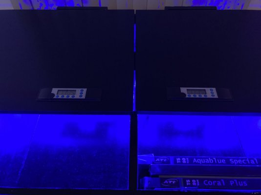
Final notes. All wire is 18 AWG 600V copper wire. All circuits are controlled by a built-in digital clock/timer that can be seen in the lower right part of the panel. Each digital clock/timer switches three separate circuits using electromagnetic relays. Each panel has two pigtail sockets into which the 12V exhaust fans are plugged once the panel is in place. The fans are driven by standard 12V constant voltage drivers and are switched on and off with the Blue+ T5s. The T5 endcaps are waterproof. The LEDs and the moon lights are wired so that the LEDs on both panels are switched by one timer and the moon lights on both panels are switched by the other timer. The aluminum HVAC tape is neutral grounded.
Photo showing the canopy frame and additional 1x6 pine boards that I pre-finished for later use. The plan is to set the stand up in it’s final location, have the glass for the aquarium delivered and put together using braces and silicone spacers. Have all the glass panels siliconed together using the injection method, and then have the prefinished 1x6 pine boards installed around the bottom of the aquarium so there will be matching fascia boards at the bottom and at the top of the aquarium. I anticipate there will be 23 full inches in height of front glass viewing area. The front glass panel will be low-iron glass.Final notes. All wire is 18 AWG 600V copper wire. All circuits are controlled by a built-in digital clock/timer that can be seen in the lower right part of the panel. Each digital clock/timer switches three separate circuits using electromagnetic relays. Each panel has two pigtail sockets into which the 12V exhaust fans are plugged once the panel is in place. The fans are driven by standard 12V constant voltage drivers and are switched on and off with the Blue+ T5s. The T5 endcaps are waterproof. The LEDs and the moon lights are wired so that the LEDs on both panels are switched by one timer and the moon lights on both panels are switched by the other timer. The aluminum HVAC tape is neutral grounded.
Last edited:
Duplicate post
Last edited:
Projects with Sam
5000 Club Member
View BadgesPartner Member 2024
Hospitality Award
Midwest Reefer
Rock Pool Reef Keepers
My Tank Thread
My Aquarium Showcase
nice lights! those are some serious t5s!
Similar threads
- Price: 500
- Shipping NOT Available
- Replies
- 0
- Views
- 313
- Replies
- 1
- Views
- 105
- Replies
- 59
- Views
- 2,338


