Debugging a busted Radion XR30w

aruns

Community Member
View Badges
Joined
May 17, 2018
Messages
56
Reaction score
39
Location
Seattle
Rating - 0%
0   0   0
One of the 2 Radion G3 XR30Ws I have suddenly stopped working. When I power up the unit, all the LEDs come on at once, stay on for a second and then power off. The fan continues to run and the indicator LED continuously flashes red/green. According to the manual, this indicates driver over-temperature error

Using my other working radion and it's power brick, I isolated the issue to one of the two LED array PCBs. When I switch out the faulty LED array with one from the working unit, the whole unit starts working.

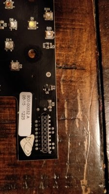
Upon examining the LED array, other than the LEDs , I see what looks like a thermister (going by it's label RT1), a couple of capacitors and a 3-pin IC. Looks like the only active component here is the IC (labeled U1) and that's the most likely candidate that's not working. I verified that all the LEDs power up during the 1 second when they light up during boot.

I have attached a picture of the LED board. I have also probed the components on the board using a multimeter and have come up with a sketch of how they are connected (pic attached)

From what I can tell, the components are part of a temperature sensing circuit. Can anyone tell what component U1? Also, R3 looks like a resistor, but am not sure about the '000' marking.

1) Any suggestions on how I can debug this further.
2) Given that the other LED array on the XR30w has it's own temp circuit, is there a way I can bypass this whole faulty circuit on this board?
3) Can anyone tell what R3 and U1 components are?

I have requested ecotech for a replacement board, not sure if they are going to have any in stock given that this is a g3 radion. I am hoping to diagnose the issue and find a solution meanwhile. Appreciate any insights from the experts.

Tagging @theatrus

IMG_20200411_231342.jpg

IMG_20200411_232420.jpg


IMG_20200411_231342.jpg
 

theatrus

Valuable Member
View Badges
Joined
Mar 26, 2016
Messages
1,966
Reaction score
3,360
Location
Sacramento, CA area
Rating - 0%
0   0   0
You're right that RT1 is most likely a thermistor, and it looks like one. I'd expect it to measure about 10k ohms at 25C.

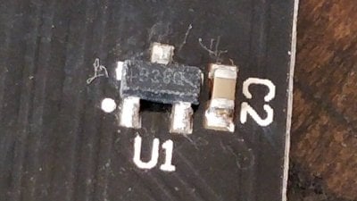
R3 looks like a 0 ohm jumper (common for hopping over traces on a metal core PCB). No idea on U1 based on the picture - can you zoom in on the three letter code on the package? It may get us closer. Its probably an ID chip or some 1-wire device.
 
OP
OP
A

aruns

Community Member
View Badges
Joined
May 17, 2018
Messages
56
Reaction score
39
Location
Seattle
Rating - 0%
0   0   0
Thanks @theatrus .

The thermistor resistance is around 25Kohms. Of course, R3 is a 0 ohm, I should have just measured it :)

The markings on the IC are very difficult to discern, I have attached a picture. Looks like 'B38Q'

IMG_20200412_090330.jpg
 
OP
OP
A

aruns

Community Member
View Badges
Joined
May 17, 2018
Messages
56
Reaction score
39
Location
Seattle
Rating - 0%
0   0   0
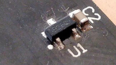
A little bit of rubbing alcohol helped. Looks like 'B28Q' now.

It could be a SMD BJT, thought not clear about the function

IMG_20200412_101752.jpg
 

theatrus

Valuable Member
View Badges
Joined
Mar 26, 2016
Messages
1,966
Reaction score
3,360
Location
Sacramento, CA area
Rating - 0%
0   0   0
Microchip UNI -IO single wire EEPROM


B2 is industrial temp range 11AA02 family.

20k is about 10C on a 10k thermistor.


Nothing seems amiss at first go -how is the fan? If there is a dodgy joint I expect it to show up after the board has warmed for more than a few seconds.
 
OP
OP
A

aruns

Community Member
View Badges
Joined
May 17, 2018
Messages
56
Reaction score
39
Location
Seattle
Rating - 0%
0   0   0
The fan itself seems fine. It's running even with LEDs not powering on.

If I replace this LED board with another from my other working Radion, then this while unit works (LEDs light up and stay powered on, no more error led indication)

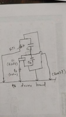
I made a mistake with the earlier schematic I posted, have now attached a new pic of what I can tell is the correct connection diagram.

Also, could you tell me how you linked 'B28Q' to the 1-wire eeprom part?

Any guesses on what would be it's use? Perhaps store board ID?

Thanks

IMG_20200412_172609.jpg
 

theatrus

Valuable Member
View Badges
Joined
Mar 26, 2016
Messages
1,966
Reaction score
3,360
Location
Sacramento, CA area
Rating - 0%
0   0   0
If I replace this LED board with another from my other working Radion, then this while unit works (LEDs light up and stay powered on, no more error led indication)

I made a mistake with the earlier schematic I posted, have now attached a new pic of what I can tell is the correct connection diagram.

If you have time for a process of eliminatio, I'd measure the voltage on a running unit between one side of RT1 and what you've labeled as GND, and compare the numbers between the two boards. This looks like the only temperature monitoring component on the board, and its possible even a little heat gets it totally out of whack very quickly.

You might need to flay some wires out of the assembly to measure.

Also, could you tell me how you linked 'B28Q' to the 1-wire eeprom part?

Any guesses on what would be it's use? Perhaps store board ID?

A bit of a process of elimination.

- Probably not a temperature diode or other device, since there already is a thermistor on board.
- A simple diode or FET or BJT doesn't make sense, since why?
- Probably a 1-wire device, as they exist in three (or sometimes two) terminal devices. The most logical thing they could be was an EEPROM identifying the board.
- Google B28 SOT-23, end up on some random Chinese website which doesn't tell you much except they claim "Memory device" (another clue). They helpfully wanted $5 by PayPal to get more information, which is a pretty good sales pitch right there :)
- Look at a few common 1-wire EEPROM datasheets to see if we get lucky.

The problem with the tiny ICs is the marking codes are so short, and not always just a part number as in this case, where it includes some lot number or other manufacturing code after the part number.

I suspect it identifies the LED board, and may contain data on whats installed or max currents or other information, or perhaps which channels are loaded if the board was designed for other uses. Dumping it wouldn't likely tell us too much unless we found other boards which different values which we could extrapolate something from.
 
OP
OP
A

aruns

Community Member
View Badges
Joined
May 17, 2018
Messages
56
Reaction score
39
Location
Seattle
Rating - 0%
0   0   0
I measured the voltages, they are about the same between the bad board and one that's working.

I did however notice that with all the probing, my radion is now starting without LEDs on, indicator LED blue. Then when I manually control the lights from app, LEDs turn on and stay that way for several seconds, then switch off. Indicator LED then starts blinking red/green.

I am now suspecting that this could be a bad solder joint somewhere. Will try reflowing the joints when I get access to a soldering station.

Thanks for sharing how you identified the part @theatrus, very useful.
 

theatrus

Valuable Member
View Badges
Joined
Mar 26, 2016
Messages
1,966
Reaction score
3,360
Location
Sacramento, CA area
Rating - 0%
0   0   0
I measured the voltages, they are about the same between the bad board and one that's working.

I did however notice that with all the probing, my radion is now starting without LEDs on, indicator LED blue. Then when I manually control the lights from app, LEDs turn on and stay that way for several seconds, then switch off. Indicator LED then starts blinking red/green.

I am now suspecting that this could be a bad solder joint somewhere. Will try reflowing the joints when I get access to a soldering station.

Thanks for sharing how you identified the part @theatrus, very useful.

Also clean out the connectors with IPA (however precious that is these days :)). Something is causing it to misread, which can be a bad ground, bad thermistor connection, etc.
 

drcole

Well-Known Member
View Badges
Joined
Jul 1, 2015
Messages
876
Reaction score
494
Rating - 0%
0   0   0
ANy update here?? I am nowhere close to as knowledgeable as you on electrical, but I have a radion doing this too and hoping I can try and fix it.
 
OP
OP
A

aruns

Community Member
View Badges
Joined
May 17, 2018
Messages
56
Reaction score
39
Location
Seattle
Rating - 0%
0   0   0
Hi, I isolated the issue to a busted LED board. Beyond that couldn't proceed. I ended up emailing/calling Ecotech support to see if they could send me a replacement LED board
While they were nice to deal with, all I got was the standard, and understandably, "you need to ship it out to us so we can take a look"

I ended up shipping the module to them and Ecotech said it was a short on the LED board. However, they had no Gen3 pro boards in stock and the cost for replacement was also not worth it. So ended up getting a new radion.
 

Bubbles, bubbles, and more bubbles: Do you keep bubble-like corals in your reef?

  • I currently have bubble-like corals in my reef.

    Votes: 25 34.7%
  • I don’t currently have bubble-like corals in my reef, but I have in the past.

    Votes: 8 11.1%
  • I don’t currently have bubble-like corals in my reef, but I plan to in the future.

    Votes: 24 33.3%
  • I don’t currently have bubble-like corals in my reef and have no plans to in the future.

    Votes: 13 18.1%
  • Other.

    Votes: 2 2.8%
Back
Top