


- Joined
- Aug 11, 2018
- Messages
- 677
- Reaction score
- 1,121
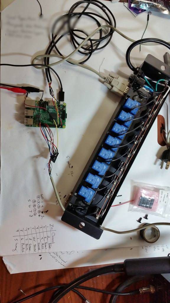
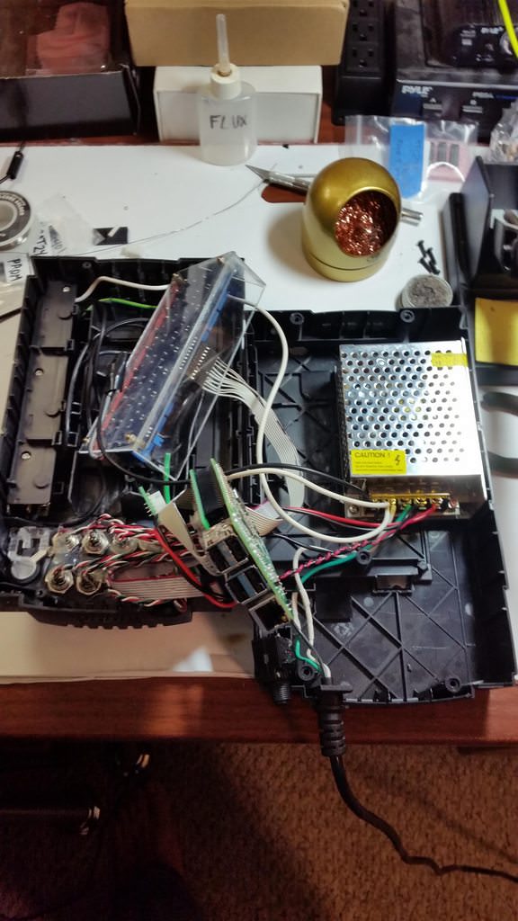
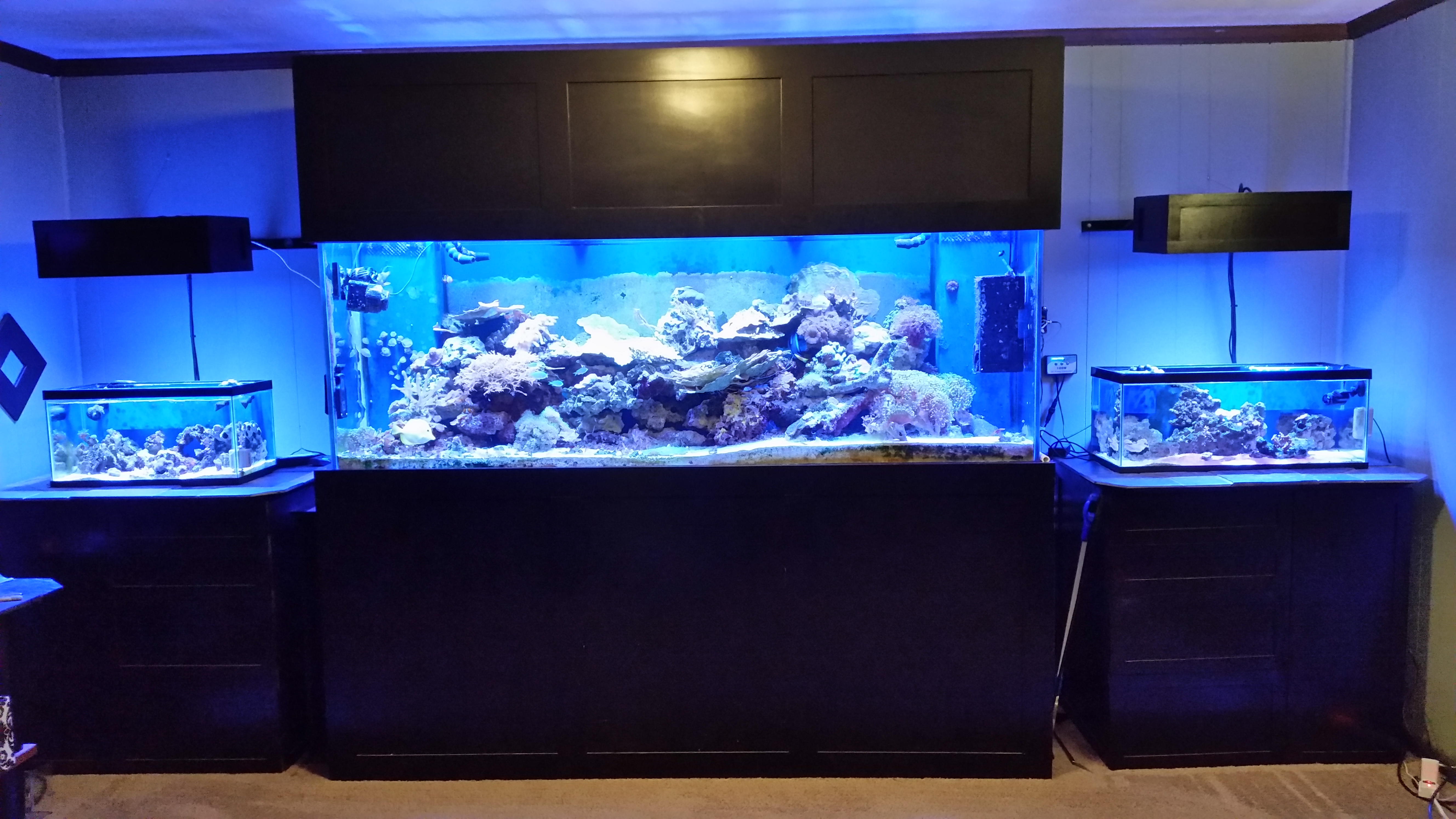
This thread will be my build log for reef-pi. It will replace RKL and a custom light controller on my reef tanks.
I have a Digital Aquatics RKL, but they went out of business and I'll no longer be able to receive support or replacement parts. That led me to reef-pi (https://reef-pi.github.io/), so I started contributing to the project.
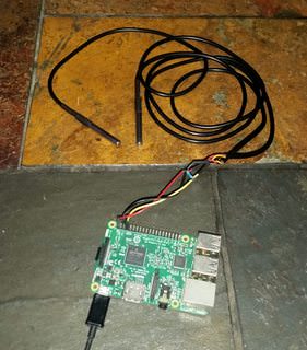
I started with the instructions on adafruit (https://learn.adafruit.com/reef-pi-installation-and-configuration?view=all). I glossed over the rpi set up and just downloaded Raspbian Stretch Lite, extracted the image, and flashed it to the sd card using Etcher (https://etcher.io/). Next, I enabled ssh by adding a file call ssh to the sd card root, and pre-configured wifi by adding wpa_supplicant.conf (as described here https://raspberrypi.stackexchange.com/questions/10251/prepare-sd-card-for-wifi-on-headless-pi).
Next, I booted the pi and waited for it to join the network. I used the default credentials (pi/raspberry) to log in. First steps were to change login credentials and permanently enable ssh using raspi-config. I had a few hiccups from using low quality power supply and usb cables, but eventually I fixed that. I followed the rest of the instructions and finally have reef-pi running!
I think temperature sensors or power module will be next.
I have a Digital Aquatics RKL, but they went out of business and I'll no longer be able to receive support or replacement parts. That led me to reef-pi (https://reef-pi.github.io/), so I started contributing to the project.
I started with the instructions on adafruit (https://learn.adafruit.com/reef-pi-installation-and-configuration?view=all). I glossed over the rpi set up and just downloaded Raspbian Stretch Lite, extracted the image, and flashed it to the sd card using Etcher (https://etcher.io/). Next, I enabled ssh by adding a file call ssh to the sd card root, and pre-configured wifi by adding wpa_supplicant.conf (as described here https://raspberrypi.stackexchange.com/questions/10251/prepare-sd-card-for-wifi-on-headless-pi).
Next, I booted the pi and waited for it to join the network. I used the default credentials (pi/raspberry) to log in. First steps were to change login credentials and permanently enable ssh using raspi-config. I had a few hiccups from using low quality power supply and usb cables, but eventually I fixed that. I followed the rest of the instructions and finally have reef-pi running!
I think temperature sensors or power module will be next.