Frag Tank Build

OP
OP
Chameleon

Chameleon

Valuable Member
View Badges
Joined
Jan 5, 2012
Messages
2,249
Reaction score
88
Location
Rockville, MD
Rating - 0%
0   0   0
I got the electrical in order. I ran 12-3 Romex wire from the 200A main panel on a 20A piggyback breaker to the basement. There I installed one outlet without GFCI and another GFCI protected all off one 20A circuit. The other 20A line I am leaving open for now. If I run into problems with two much power on the circuit I can easily put in a few more outlets on the other 20A circuit down the road (this is why I went with 12-3 wire). I bypassed my 100A sub-panel so I wouldn't be pulling from the rest of the houses electrical and went straight to the 200A main pannel. Also the 100A sub-panel would have been a pain to fish a wire to and probably involved some drilling so I saved some time here too.

I plan to put most things on the GFCI outlet, but may put the return pump on the non protected outlet as I dont want nuisance trips to shut down the return. The return is external so I think this will be a safe route to go.

Let me know if yall have suggestions, and BTW this is my first time doing electrical so when I tested my outlets I was pretty ecstatic to see them work. I was really nervous working on a live 220v 200A panel that I couldn't turn off, but I was very careful so things went smooth.
 
OP
OP
Chameleon

Chameleon

Valuable Member
View Badges
Joined
Jan 5, 2012
Messages
2,249
Reaction score
88
Location
Rockville, MD
Rating - 0%
0   0   0
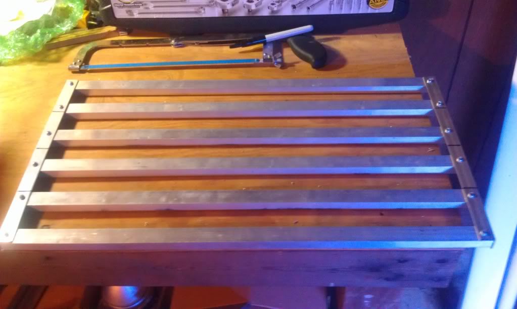
Finally got to the LEDs. I copied a bit of Harry from Huntsville for the heat sink. Instead of one inch square aluminum tube I used a combo of channel and angle 3/4 inch. Pics to come
 
OP
OP
Chameleon

Chameleon

Valuable Member
View Badges
Joined
Jan 5, 2012
Messages
2,249
Reaction score
88
Location
Rockville, MD
Rating - 0%
0   0   0
I put the leds on two days ago, but then I realized I had bought the wrong thermal compound. I got the paste instead of the plaster so the leds wouldn't stick. Now I am waiting on the plaster to come in and dreading the task of cleaning off the old paste from the leds and rack.
 
OP
OP
Chameleon

Chameleon

Valuable Member
View Badges
Joined
Jan 5, 2012
Messages
2,249
Reaction score
88
Location
Rockville, MD
Rating - 0%
0   0   0
BTW I have never cut aluminum with a circular saw before, but it really works well. Just make sure to wear gloves and eye protection
 
OP
OP
Chameleon

Chameleon

Valuable Member
View Badges
Joined
Jan 5, 2012
Messages
2,249
Reaction score
88
Location
Rockville, MD
Rating - 0%
0   0   0
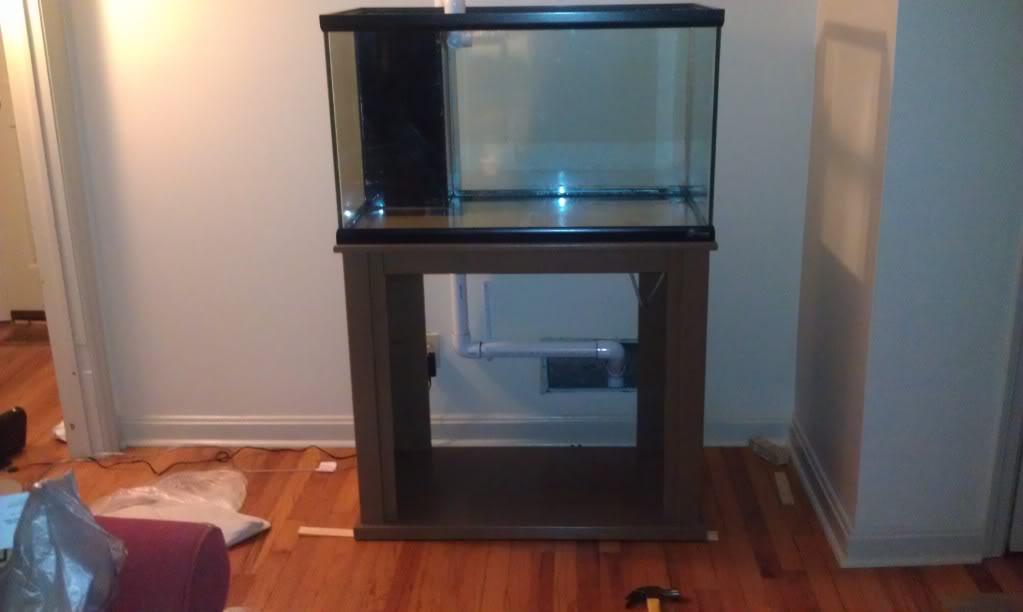
Not frag tank related, but I got the display almost functional again. hood and doors still need some touch up paint so they are missing but that lets you see the return plumbing. the overflow plumbing is hopefully tonight's project
 

Blake11rebel

Active Member
View Badges
Joined
Sep 4, 2011
Messages
205
Reaction score
5
Location
Cropwell,AL
Rating - 0%
0   0   0
I like your frag tank. I got a wp40 for my FOWLR 90g and I'm happy with it. Do you use the lower setting for the 40 breeder?
 
OP
OP
Chameleon

Chameleon

Valuable Member
View Badges
Joined
Jan 5, 2012
Messages
2,249
Reaction score
88
Location
Rockville, MD
Rating - 0%
0   0   0
I like your frag tank. I got a wp40 for my FOWLR 90g and I'm happy with it. Do you use the lower setting for the 40 breeder?
Nope its on W1 and I think it is a good amount of flow for the 40. Sorry for the late response.

Well I got back to my led build this weekend and wired everything up only to find 2 of the 5 drivers didn't fire the leds. I'm checking over my soldering tonight. Last time I built leds they fired without a problem so I guess I got a little too haphazard when it came to soldering this time. Pics to come.
 
OP
OP
Chameleon

Chameleon

Valuable Member
View Badges
Joined
Jan 5, 2012
Messages
2,249
Reaction score
88
Location
Rockville, MD
Rating - 0%
0   0   0
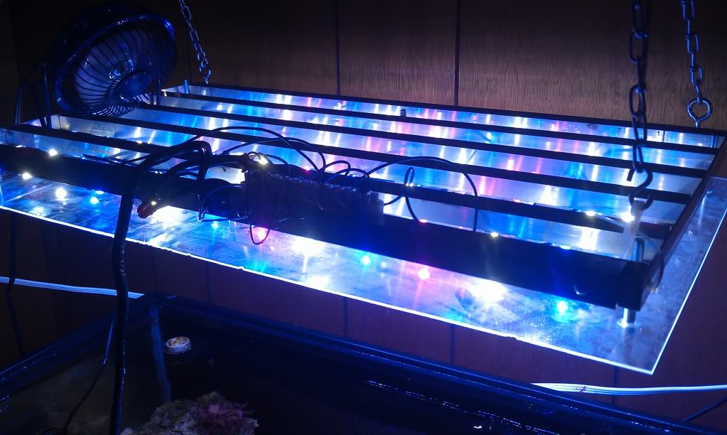
LEDs almost done! Here are some pics of the almost finished product. I still need to add a splash shield and fan. Also want to put in switches for individual channels and the dimmer switches.
Whole thing:

On light terminal:

Project box with drivers and power supply:

Wiring in box:


All fired up (24 CW 24 RB 10 hyper violet):
 

markkazdad

Well-Known Member
View Badges
Joined
Jul 30, 2012
Messages
632
Reaction score
0
Location
North Alabama
Rating - 0%
0   0   0
I like the project box idea. Is the splash shield just a piece of acrylic from a big box store?
 

H@rry

Troll
View Badges
Joined
Aug 4, 2007
Messages
3,397
Reaction score
551
Location
Huntsville, AL
Rating - 0%
0   0   0
Looks like you've got it going on! I like it. One thing, you might want to get the power supply out of your project box so the fan can keep it cool. The pot on the power supply allows you to make small adjustments to the voltage. I think most of mine will go from about 45v - 52v.

I see you used thermostat wire. I was using serial cables until I did one tank that was farther away from the controller than the others and had to use a 12' cable instead of the 6' that I used on the first ones. The LEDs were noticeably dimmer than the others. I checked the current and it was only 210 mA. I replaced the serial cable with thermostat wire and it went up to 670 mA.

Now all you need is a controller!
 
Last edited:

When to mix up fish meal: When was the last time you tried a different brand of food for your reef?

  • I regularly change the food that I feed to the tank.

    Votes: 45 21.5%
  • I occasionally change the food that I feed to the tank.

    Votes: 72 34.4%
  • I rarely change the food that I feed to the tank.

    Votes: 69 33.0%
  • I never change the food that I feed to the tank.

    Votes: 19 9.1%
  • Other.

    Votes: 4 1.9%
Back
Top