

I belive it will be one resistor per driver.

LDD meanwell resistor
Where does the resistor go on the LDD drivers go, to stop them going full tilt when the power is off?? Thanks.
Suppose anywhere along the dim wire is just fine..
As to ganging say 4 driver dim wires suppose one could use one resistor but value ???
Bunch of over my pay grade math dealing with it here:

Meanwell LDD driver: for those who want to dim to 0 using Arduino
This is a little test video I made using Meanwell LDD-1000H and Bridgelux BXRA-40E2200 Neutral White array: The array itself is very powerful, so its not going to dim to moonlight brightness, but regular 3W LEDs do. They barely glow at 1/255 level. Enjoy!www.nano-reef.com
"Seems" fine to use just one 10K per PWM output no matter how many are eventually attached to it in the end.
SOMEONE can verify..I know a non-answer to your exact question but a trail of sorts..
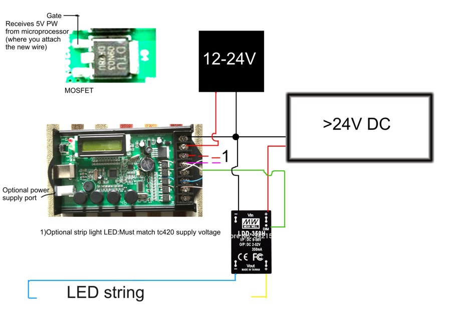
childish diagram but a visual of your question.

The wiring gets confusing if I use one resistor for four drivers, I've got some 4.7k ohm resistors from what I've read is I can use them also, though 10k is preferred, on my old LDD hw board I didn't use resistors on two of the pwm's didn't have an issue as there was no way of rebooting the Arduino device without connecting to a computer. Though now I'm using reef pi on my lights and everything else, I'll be making a pi zero with a PCA 9685 hat to reduce wires going to the lights and keeping the PSU up there too.