Guide's for a DIY LED strip for a 25cm tank

PeterLL

Active Member
View Badges
Joined
Aug 12, 2018
Messages
392
Reaction score
461
Rating - 0%
0   0   0
Hi everyone,
I've got a wee 25cm pico thats long and narrow, so looking for a wee LED strip to make:
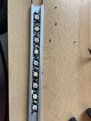
Something like this:
DIY LED.jpg


I've not done anything like this before, and would need a full on guide from how to get it plugged to mains, to soldering on the LED's to what housing I'd need, if anyone can point me in the right direction?
THank You
 
OP
OP
PeterLL

PeterLL

Active Member
View Badges
Joined
Aug 12, 2018
Messages
392
Reaction score
461
Rating - 0%
0   0   0
Okay I realise It'll be helpful if I give a little more detailed to what I'm thinking.

So, would this work:
1) To connect to a mains, a USB wall plug with power cable (https://futureeden.co.uk/collection...s/2-core-mains-flex-cable?variant=23776612422)

soldered one end to a USB shell (https://www.hobbytronics.co.uk/usb-...MIhLy3n4rL6gIVU4BQBh0-gg6QEAQYASABEgKQjfD_BwE)

and the other to a LED driver (https://futureeden.co.uk/collection.../12w-300ma-constant-current-led-driver-20-43v)

2) More power cable soldered to the other end of the LED driver and then soldered to either a LED PCB (https://futureeden.co.uk/collection...mm-pcb-8-led-in-series?variant=14038195568724),

OR to some star LED's (https://futureeden.co.uk/collections/1w-high-power-led-with-pcb-heatsink-all-colours-1).

One question though is would I just solder power cable between each individual star LED, or how are they connected?

3) Either the Star LED's or the PCB is then thermal glued onto an aluminium heatsink, and then that is the LED complete right?

Thank You so much
 

Michael Lane

Well-Known Member
View Badges
Joined
Aug 11, 2018
Messages
677
Reaction score
1,123
Rating - 0%
0   0   0
I don't follow how you are planning to use the USB connector.

Based on what you've described, this is basically what you want based on the LED driver you linked. You would still need to get a heatsink and use some thermal glue to attach the LEDs.

1594864136422.png
 
OP
OP
PeterLL

PeterLL

Active Member
View Badges
Joined
Aug 12, 2018
Messages
392
Reaction score
461
Rating - 0%
0   0   0
I don't follow how you are planning to use the USB connector.

Based on what you've described, this is basically what you want based on the LED driver you linked. You would still need to get a heatsink and use some thermal glue to attach the LEDs.

Legend mate thank you, that was a lot simpler than I was making it out to be haha.

I'll ditch the USB idea as well. So I have got a 55 quid shopping list for this including the light:
Bare end plug attached to LED driver, and then from the LED driver to the star LED's like shown. The LED's directly thermal sillicone'd onto a aluminium LED profile, which will have LED heatsinks thermal silicone'd onto the top of the profile. Then Some aluminium flat bars and L brackets to make a wee stand and that should be it lol. Excited to give this a go, just need to choose what 9 LED's to run
 

Michael Lane

Well-Known Member
View Badges
Joined
Aug 11, 2018
Messages
677
Reaction score
1,123
Rating - 0%
0   0   0
@Michael Lane Sorry to bump you again, how would these be connected in the series youve shown above? https://futureeden.co.uk/collection...nm-520-530nm-460-470nm-with-star-pcb-heatsink
Thank You
These are basically 3 LEDs on a single board, so you would probably be limited to 4 of these. You'll have to connect them as though they were individual boards in order to make sure the majority of the current doesn't flow through the red LEDs.

Her
1594955771427.png

Here's another way to look at it that shows the traces on the stars. This example routes the power through green, then blue, then red.

1594956079199.png


If you need to use more than 4 of these then I would recommend a separate driver for each color. Then you could have 11-12 of these stars.
 
OP
OP
PeterLL

PeterLL

Active Member
View Badges
Joined
Aug 12, 2018
Messages
392
Reaction score
461
Rating - 0%
0   0   0
These are basically 3 LEDs on a single board, so you would probably be limited to 4 of these. You'll have to connect them as though they were individual boards in order to make sure the majority of the current doesn't flow through the red LEDs.

Her
1594955771427.png

Here's another way to look at it that shows the traces on the stars. This example routes the power through green, then blue, then red.

1594956079199.png


If you need to use more than 4 of these then I would recommend a separate driver for each color. Then you could have 11-12 of these stars.

Makes sense, thank you so much.
So I was only planning two of these in series with violets, blues and whites, but apart from the additional wiring over the LED star, connecting is that same by just connecting the pink to the plus of the violet, blue, white etc. LED next in the series. Its a bit weird but it wants me to just wire directly over the LED light unless you hold the wire in place around the 'bulb'?
 

Michael Lane

Well-Known Member
View Badges
Joined
Aug 11, 2018
Messages
677
Reaction score
1,123
Rating - 0%
0   0   0
Makes sense, thank you so much.
So I was only planning two of these in series with violets, blues and whites, but apart from the additional wiring over the LED star, connecting is that same by just connecting the pink to the plus of the violet, blue, white etc. LED next in the series. Its a bit weird but it wants me to just wire directly over the LED light unless you hold the wire in place around the 'bulb'?
Yeah. You don't want to wire over the LED. It's more work to draw a curved line, so the illustrations are not exactly what you would do. I would curve a bit of wire around the star.

You can wire them any way that makes sense to you as long as you keep everything in series. That means you could just connect all the red channels, then loop back from the end of the reds to the start of the greens, then do the same thing for blue. It just uses more wire, and I always seem to have a wire shortage...
 
OP
OP
PeterLL

PeterLL

Active Member
View Badges
Joined
Aug 12, 2018
Messages
392
Reaction score
461
Rating - 0%
0   0   0
Yeah. You don't want to wire over the LED. It's more work to draw a curved line, so the illustrations are not exactly what you would do. I would curve a bit of wire around the star.

You can wire them any way that makes sense to you as long as you keep everything in series. That means you could just connect all the red channels, then loop back from the end of the reds to the start of the greens, then do the same thing for blue. It just uses more wire, and I always seem to have a wire shortage...
Thank you so much, I’ve got the wires in place ready to be sorted, so they look good/correct?

B8E636AE-39AF-431B-A5E7-34F4812E8D62.jpeg
 
OP
OP
PeterLL

PeterLL

Active Member
View Badges
Joined
Aug 12, 2018
Messages
392
Reaction score
461
Rating - 0%
0   0   0
Anyone know of any way of testing if the circuit is working without wiring it into the driver yet?
Cheers
 

Michael Lane

Well-Known Member
View Badges
Joined
Aug 11, 2018
Messages
677
Reaction score
1,123
Rating - 0%
0   0   0
I can't completely tell if it's correct, but it looks like it's wired correctly. Some of the LEDs and wires are hard to see though.

If you have a bench power supply, then you can test by setting the voltage to ~3 or 4 volts and setting the current limit to a few milliamps. Then you can poke the power supply leads across each LED in the way that you think is correct.

If that works out, then you can double the voltage and test a couple of LEDs in series to be sure.
 
OP
OP
PeterLL

PeterLL

Active Member
View Badges
Joined
Aug 12, 2018
Messages
392
Reaction score
461
Rating - 0%
0   0   0
I can't completely tell if it's correct, but it looks like it's wired correctly. Some of the LEDs and wires are hard to see though.

If you have a bench power supply, then you can test by setting the voltage to ~3 or 4 volts and setting the current limit to a few milliamps. Then you can poke the power supply leads across each LED in the way that you think is correct.

If that works out, then you can double the voltage and test a couple of LEDs in series to be sure.
Awesome thank you so much - I’ve (dodgily) soldered it all in

hopefully it’s all done correctly although I’m a bit concerned about the connection quality on the solders.
Also I do not have a bench power supply, is there anything else I can use like a batter or something?
 
OP
OP
PeterLL

PeterLL

Active Member
View Badges
Joined
Aug 12, 2018
Messages
392
Reaction score
461
Rating - 0%
0   0   0
OKay I messed up with the driver, while I order a new one, If i had a 12W driver trying to power 9 3W LED's, should I expect the LED's to be dim, flickering etc. or just not light at all?
Trying to work out if the circuit is bad or its purely the driver, cheers
 

oreo54

5000 Club Member
View Badges
Joined
Sep 18, 2017
Messages
5,614
Reaction score
3,456
Rating - 0%
0   0   0
OKay I messed up with the driver, while I order a new one, If i had a 12W driver trying to power 9 3W LED's, should I expect the LED's to be dim, flickering etc. or just not light at all?
Trying to work out if the circuit is bad or its purely the driver, cheers

Voltage out of the driver is important here..
Using the pic from your post on THAT driver.
It looks like it says 36V max. 18v min (??? hard to see). Both numbers are important.
the 6-10 "watt" thing gives yo an idea of the constant current it's set for.
Soo probably around 350mA which is fairly standard.

Your "12W" driver may light or may not light your string.. It's the available voltage that matters..
Assuming standard-ish blues/whites your driver needs to be capable of providing something like 3.7 X 9 = 33.3 volts.
A 12V driver can have current set at anything.. Say 250mA and be capable of 48V out
A 1 A 12W driver will only output 12V max..

In other words the wattage of the driver tells you nothing really.


After you reach the V(f) of the sum of the voltages of the series diodes THEN one can talk watts..

As to testing diodes.. Any digital VOM set on ohms (low) or diode should be able to test a single emitter..
Obviously since they are diodes they only conduct in one direction.
Place point of sale prob on point of sale pad of diode 1 and then neg pad of diode 2. Diode one should light dimly.

Also check each pad (plus and minus) to accidental shorts to the heat sink..point of sale pad to heat sink neg pad to heat sink.
 
OP
OP
PeterLL

PeterLL

Active Member
View Badges
Joined
Aug 12, 2018
Messages
392
Reaction score
461
Rating - 0%
0   0   0
Voltage out of the driver is important here..
Using the pic from your post on THAT driver.
It looks like it says 36V max. 18v min (??? hard to see). Both numbers are important.
the 6-10 "watt" thing gives yo an idea of the constant current it's set for.
Soo probably around 350mA which is fairly standard.

Your "12W" driver may light or may not light your string.. It's the available voltage that matters..
Assuming standard-ish blues/whites your driver needs to be capable of providing something like 3.7 X 9 = 33.3 volts.
A 12V driver can have current set at anything.. Say 250mA and be capable of 48V out
A 1 A 12W driver will only output 12V max..

In other words the wattage of the driver tells you nothing really.


After you reach the V(f) of the sum of the voltages of the series diodes THEN one can talk watts..

As to testing diodes.. Any digital VOM set on ohms (low) or diode should be able to test a single emitter..
Obviously since they are diodes they only conduct in one direction.
Place point of sale prob on point of sale pad of diode 1 and then neg pad of diode 2. Diode one should light dimly.

Also check each pad (plus and minus) to accidental shorts to the heat sink..point of sale pad to heat sink neg pad to heat sink.
Thank you so much but I am also incredibly lost hahah.
So the info on my driver is in my next reply.
So essentially, for 9, 3W LED's I need a driver capable of atleast 27W and 33.3V or??

Also I'll look into getting a Multimeter then seems like it'll stop me driving my head into a wall haha
 
OP
OP
PeterLL

PeterLL

Active Member
View Badges
Joined
Aug 12, 2018
Messages
392
Reaction score
461
Rating - 0%
0   0   0
Voltage out of the driver is important here..
Using the pic from your post on THAT driver.
It looks like it says 36V max. 18v min (??? hard to see). Both numbers are important.
the 6-10 "watt" thing gives yo an idea of the constant current it's set for.
Soo probably around 350mA which is fairly standard.

Your "12W" driver may light or may not light your string.. It's the available voltage that matters..
Assuming standard-ish blues/whites your driver needs to be capable of providing something like 3.7 X 9 = 33.3 volts.
A 12V driver can have current set at anything.. Say 250mA and be capable of 48V out
A 1 A 12W driver will only output 12V max..

In other words the wattage of the driver tells you nothing really.


After you reach the V(f) of the sum of the voltages of the series diodes THEN one can talk watts..

As to testing diodes.. Any digital VOM set on ohms (low) or diode should be able to test a single emitter..
Obviously since they are diodes they only conduct in one direction.
Place point of sale prob on point of sale pad of diode 1 and then neg pad of diode 2. Diode one should light dimly.

Also check each pad (plus and minus) to accidental shorts to the heat sink..point of sale pad to heat sink neg pad to heat sink.
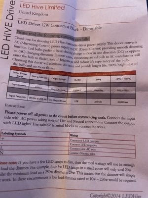
Thank you so much but I am also incredibly lost hahah.
So the info on my driver is:

29E1F46A-3FC7-47FD-9B1F-CE3B7F9F4AA6.jpeg
 
OP
OP
PeterLL

PeterLL

Active Member
View Badges
Joined
Aug 12, 2018
Messages
392
Reaction score
461
Rating - 0%
0   0   0
How come I struggle to find such high voltage drivers, when 99% of them I see are maximum 12V? Seems odd considering its powering only 9 LED's
 

oreo54

5000 Club Member
View Badges
Joined
Sep 18, 2017
Messages
5,614
Reaction score
3,456
Rating - 0%
0   0   0
How come I struggle to find such high voltage drivers, when 99% of them I see are maximum 12V? Seems odd considering its powering only 9 LED's

That just looks like a switching power supply they call a driver..
 

Keeping it clean: Have you used a filter roller?

  • I currently use a filter roller.

    Votes: 31 29.5%
  • I don’t currently use a filter roller, but I have in the past.

    Votes: 3 2.9%
  • I have never used a filter roller, but I plan to in the future.

    Votes: 28 26.7%
  • I have never used a filter roller and have no plans to in the future.

    Votes: 39 37.1%
  • Other.

    Votes: 4 3.8%
Back
Top