


How to make DIY RECIRCULATING BIOPELLET REACTOR

thenissantech

Well-Known Member
View Badges
Joined
Mar 4, 2013
Messages
506
Reaction score
186
Location
Maryville tn
Rating - 0%
0   0   0
Biopellets have been around for a few years, and I think they are here to stay. They are great at what they do, but unfortunately don't know when to stop doing their job. After countless hours on this forum and others I came to the conclusion that a recirculating biopellet reactor was the way to go. because all the options seem to be very pricey, I built my own that I believe is comparable to any reactor that can be bought. So, along the way I took some pics and notes of the mistakes I made and hope to pass it on to you fine people.
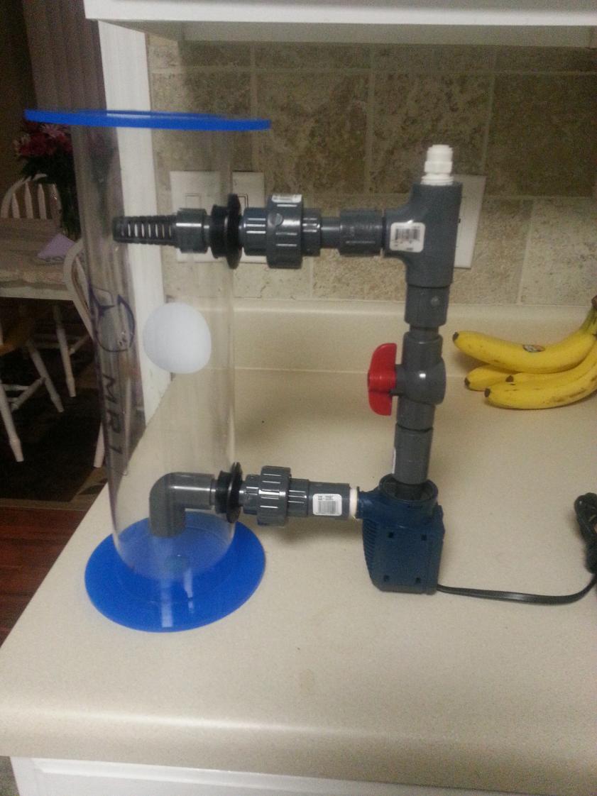
20140120_201912.jpg


Supplies:
Nextreef mr1 media reactor: amazon 49$
Quiet one 1200 250gph pump: amazon 25$
Uniseals 1/2" x2 : BRS 4$
Filter 1/2" : BRS 2$
3/8" male x 1/2" female adapter: Pex plastic supply 6$
Schedule 80 1/2" pipe: BRS 7$
Schedule 80 1/2" slip x slip union x2 : BRS 8$
Schedule 80 1/2 slip x slip elbow x2 : BRS 3.20$
Schedule 80 1/2 adapter x2 : Lowes 3$
Schedule 80 1/2 coupling x1 : Lowes 1$
Schedule 80 1/2" threaded tee: Lowes 3$
Schedule 80 1/2 ball valve: Amazon 4$
1/2" x 1/4" john gusset fitting: Lowes 3.5$
3/8" x 1/4" john gusset fitting: Lowes 3.5$
1/4" tubing: had laying around
1/4" ball valve: had laying around

This is my final design (2 before it). I'm sure parts could be ordered elsewhere, but this is where I got them. I listed so anyone could obtain the same parts to build this.

 
The first thing I acquired was a Nextreef Mr1 reactor off amazon. I used a step bit (Amazon 12$) to drill out holes for uniseals.

20140118_081101.jpg


20140118_093603.jpg


20140120_200749.jpg


I used regular schedule 40 pvc to cut different lengths to test for best fit. There was no glue used at this point. I learned this one the hard way:wacko:

Once I had the layout worked out along with all my pieces, it was time to glue.

20140120_200758.jpg
 
The pieces on the inside of the reactor just push on so they can be removed. These were the first pieces that I installed. I made the filter out of 1/2" filter and a cut off piece of 1/2" coupling. I then installed one side of each union to reactor.

20140120_200817.jpg


20140120_201258.jpg


I used the other john gusset fitting on top of the reactor for the outlet

After that I assembled the rest of my reactor. I used the tee along with adapters for my inlet john gusset fitting. Once I had her glued together I put her in the sink and water tested it.

20140120_200823.jpg


20140120_202813.jpg


What I really like is how once it's primed (no air) it drams its own water from sump!
 
The pump is pretty quiet. For the $$ it can't be beat. I installed it in the sump and all seems to be working great so far. I will update in the future and hope this thread is helpful for others. Thanks for looking

20140120_204629.jpg


ACTION SHOT!!!!

20140120_204619.jpg
 
happy to report this creation is still working great after the first few days. no results as far as p04 change yet but I will keep updated.
 
I know it has been a few months and I am looking to do something very similar. This looks like a great way to go. Super job.

Just one question. Does it self prime?
 
Thanks. Its still going strong I can adjust the output to adjust my p04.I don't keep it at 0 just a little above. Its not self priming but does bleed the air out quickly. Thanks for the kind words.
 
Thanks so much for posting this I tried to make one out of a BRS reactor and failed. I'll have to pickup an MR1 reactor now to do this, already got the uniseals/strainer from BRS. Just curious I read it a few times but I might have missed it, where did you use this part?

3/8" male x 1/2" female adapter: Pex plastic supply 6$

And the plug on the top of the reactor did you buy that or does it come with the reactor? Lastly, I'm guessing the john guest fitting on the top is the "
3/8" x 1/4" john gusset fitting: Lowes 3.5$" ?
 
Very well done!
 
I'm not understanding the recirculating. Is it possible to show the path? Do you just close and open the valve in between the top and bottom? Does the water enter and leave through the white hoses? I have a bio pellet reactor and haven't I staked it yet, but this seems the way to go.
 
I'm not understanding the recirculating. Is it possible to show the path? Do you just close and open the valve in between the top and bottom? Does the water enter and leave through the white hoses? I have a bio pellet reactor and haven't I staked it yet, but this seems the way to go.

Here's a quick paint sketch I did using the OP's testing photo, hope he/she doesn't mind. The red arrows is the recirculating path, the valve between the top/bottom halves is just to adjust the flow rate through the reactor in order to tumble the BP more/less. On a standard non-recirculating reactor the inlet pump flow determines the tumbling of the pellets AND the output of the reactor which can lead to over stripping the tank of nutrients because most neeed a high flow rate to keep the pellets in suspension. This method allows you to adjust the flow rate in the chamber with a closed loop system without affecting in/out. The green arrow is the inlet, allowing it to be mounted away/out of the sump or tank and the yellow arrow is the outflow which should have a valve on it to control out flow. You will only pull in as much water via the green arrow as you push out of the yellow arrow...hope that helps!

qldbZd0.jpg
 
Ok hgarts the way I thought, just wasn't sure whether it would affect the tumbling of the pellets. Thanks!
 
My understanding is that once it deletes the nitrates, it will start eating the good bacteria as well. I've had my reactor for awhile but haven't started using it because of not knowing how to keep the pellets from using up everything.
 
A recirculating reactor allows you to control the output of your effluent according to your bio load so that you don't strip your system of all nutrients. It also allows your pellet tumble to stay the same no matter how fast or slow your allowing the output to flow.
 
I'm just hearing about bio pellets for the 1st time. Please enlighten me on their beneficial use in a reef system. I "assume" it's for Po4 control? What's the principle and is it really an integral piece of the overall water-quality equation?

Thanks, y'all!
 
On a standard non-recirculating reactor the inlet pump flow determines the tumbling of the pellets AND the output of the reactor which can lead to over stripping the tank of nutrients because most neeed a high flow rate to keep the pellets in suspension. This method allows you to adjust the flow rate in the chamber with a closed loop system without affecting in/out. The green arrow is the inlet, allowing it to be mounted away/out of the sump or tank and the yellow arrow is the outflow which should have a valve on it to control out flow. You will only pull in as much water via the green arrow as you push out of the yellow arrow...hope that helps!

The recirculating is to allow you to use more pellets and adjust your flow rate/tumble independent of how much water is processed thus allowing you to fine tune how much nutrients is removed from the system without overdoing it and shocking the system or causing a crash.

tzsetze: Plenty of good articles out there on Biopellets and their use just do a quick search.
 
They really are more efficient at nitrate removal. Most use GFO in combination to lower phosphates as well in a system. Either that or dose nitrates but that's a whole other topic in itself.
 
I have build something simillar and it is working perfect
[video=youtube;ecF3Byq4fCc]https://www.youtube.com/watch?v=ecF3Byq4fCc&list=UUy2g3CMz-hBPQ9__epTDyWQ[/video]
 

TOP 10 Trending Threads

As a buyer, how important are auctions to you on the NEW market?

  • As a buyer I like them

    Votes: 28 34.1%
  • As a buyer I don’t care for them

    Votes: 32 39.0%
  • I don’t care either way.

    Votes: 22 26.8%
Back
Top
Home
Post thread…
Market
What's new






