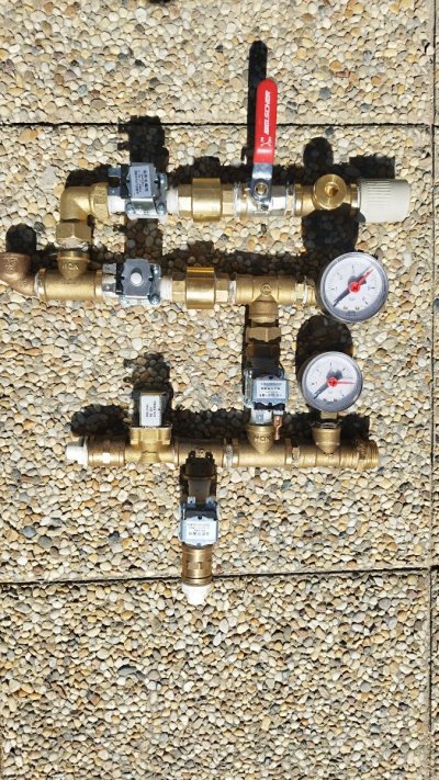
Can anyone identify and explain the purpose of this please.

Navigation
Install the app
How to install the app on iOS
Follow along with the video below to see how to install our site as a web app on your home screen.
Note: This feature may not be available in some browsers.
More options
You are using an out of date browser. It may not display this or other websites correctly.
You should upgrade or use an alternative browser.
You should upgrade or use an alternative browser.
My Current build
- Thread starter Broady2067
- Start date
- Tagged users None
Curious, looks like a coil around the AC in, connected to that red and black wire. Could be used to detect the presence of AC power, OR even the drawn current/power.Can anyone identify and explain the purpose of this please.
That blue wire looks like it is there too provide a massive health and security hazard
Lol the blue wire was in a connector. I took it off to start the re-build. I have wired it as it was. Not sure if it is drawing power for the built in volt meter or something.Curious, looks like a coil around the AC in, connected to that red and black wire. Could be used to detect the presence of AC power, OR even the drawn current/power.
That blue wire looks like it is there too provide a massive health and security hazard
Judging from the schematic on the back of the display on the picture in your first post:

It is connected to the load current by that solenoid. This probably means that your display is able to display the current or power draw of the setup.
It is connected to the load current by that solenoid. This probably means that your display is able to display the current or power draw of the setup.
Lol the blue wire was in a connector. I took it off to start the re-build. I have wired it as it was. Not sure if it is drawing power for the built in volt meter or something.
Nice one thanks. That is what i initially thought but i am no expert.Judging from the schematic on the back of the display on the picture in your first post:

It is connected to the load current by that solenoid. This probably means that your display is able to display the current or power draw of the setup.
I have made a fatal error whilst wiring up all the components. I had to replace the LM2596 buck converter. Since i am a little new to the electronic game i forgot to adjust the power down, looks like i cooked the Raspberry pi 3B+. It is now down to 5.1v is this correct.
Oh, right, thats something to watch out for, sry for your loss ...I have made a fatal error whilst wiring up all the components. I had to replace the LM2596 buck converter. Since i am a little new to the electronic game i forgot to adjust the power down, looks like i cooked the Raspberry pi 3B+. It is now down to 5.1v is this correct.
Yes, 5.1 is fine.
Thanks for the conformation. Just need ro put things on hold until i can afford a new one.Oh, right, thats something to watch out for, sry for your loss ...
Yes, 5.1 is fine.
Depending on what you want to run and your preference of WiFi or Ethernet, you can also try and get a Zero W or Zero 2 W instead, if that is available and fits the bill a bit easier.Thanks for the conformation. Just need ro put things on hold until i can afford a new one.
I think wifi is the way ro go no easy access to the router where it will be situated.Depending on what you want to run and your preference of WiFi or Ethernet, you can also try and get a Zero W or Zero 2 W instead, if that is available and fits the bill a bit easier.
Well, if you want to only run ReefPi without a screen, you can also try and get a Pi Zero W or Pi Zero 2 W.
The "W" is for WiFi, very important ... ^^
Not sure if the Pi Zero 2 W is beefy enough to run a screen next to reefPi operations. Might be.
The "W" is for WiFi, very important ... ^^
Not sure if the Pi Zero 2 W is beefy enough to run a screen next to reefPi operations. Might be.
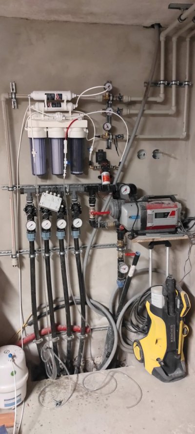
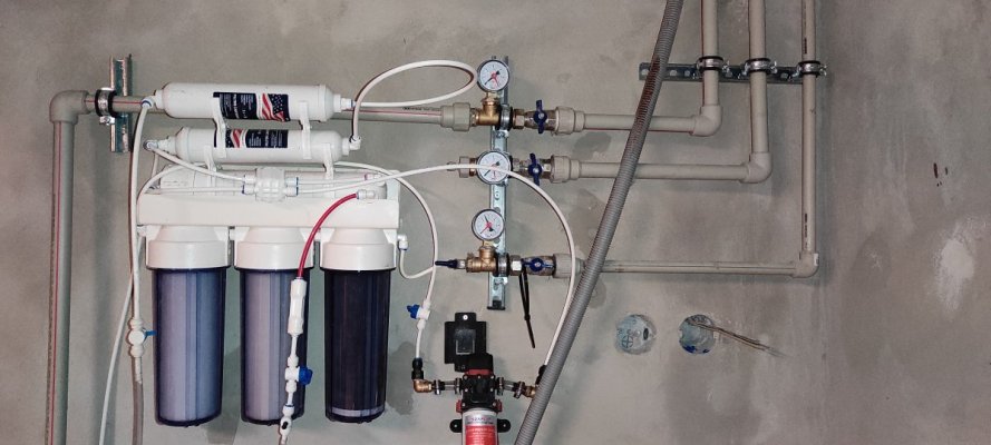
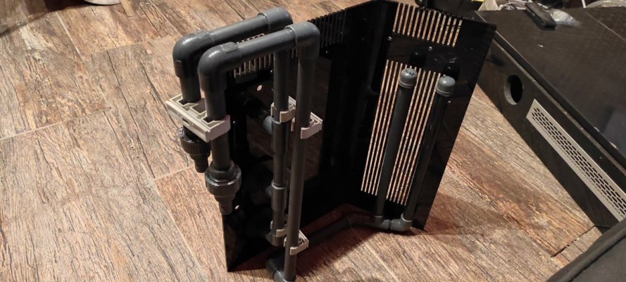
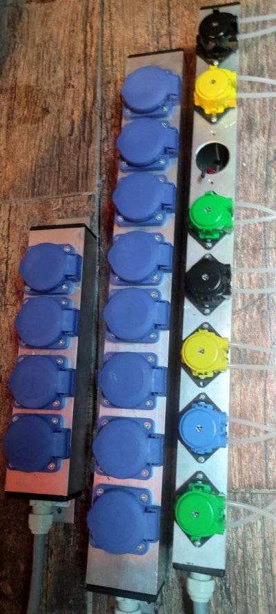
I am attaching my project with reefpi that I have connected to a freshwater aquarium. I am currently working on a new project that will serve 3 aquariums + a mixing tank

Attachments
Update. I want make an additional box to hold 8 more outlets with room for more components if i want to later. My question is how do i set this up as regards linking to the original box. I want an eight relay board connected to the outlets as in my original one and i guess i will have to power it some how using a DC buck converter. Can i use a DB9 D-sub to link to the Raspberry PI or an ESP32. Any help will be gratefully received.
@Ranjib Have you any thoughts please.Update. I want make an additional box to hold 8 more outlets with room for more components if i want to later. My question is how do i set this up as regards linking to the original box. I want an eight relay board connected to the outlets as in my original one and i guess i will have to power it some how using a DC buck converter. Can i use a DB9 D-sub to link to the Raspberry PI or an ESP32. Any help will be gratefully received.
Similar threads
- Replies
- 6
- Views
- 487
- Price: 250
- Shipping NOT Available
- Replies
- 0
- Views
- 158
- Replies
- 9
- Views
- 223


