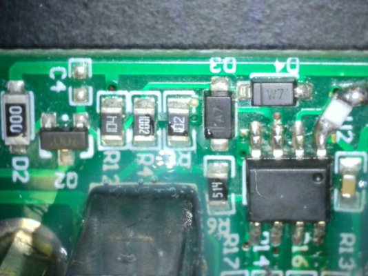
problem controling a nicrew 50W lamp

OP
OP
S

Sral

Valuable Member
View Badges
Joined
May 2, 2022
Messages
1,006
Reaction score
976
Location
Germany
Rating - 0%
0   0   0
Bummer. Its probably not critical but it probably would help understanding. FWIW, its likely a small micro controller (one ADC, one PWM), but we can probably guess the overall function from that. Will take a look later and see if I can make out something and get the rest of the brain trust theorizing.
Shouldn't it be 2 ADC and 2 PWM, one for each channel ? I agree though, overall function is probably pretty easy.

If all fails, we can try to replace the board and feed PWM from ReefPi directly in the channels. For that we would need to figure out the frequency and voltage, but that should be manageable.
 
OP
OP
S

Sral

Valuable Member
View Badges
Joined
May 2, 2022
Messages
1,006
Reaction score
976
Location
Germany
Rating - 0%
0   0   0
I've looked under the scope and my loupes and I cant see anything on U2, everything else has markings though faint. I have purchased another unit from ebay, reluctant to also crack it open but maybe I will and see if the board is different or has better markings, really stinks since the light works manually but that does me no good...
Can you make another close up picture from the same angle like the last picture, but take a look at the white input connector ? I am still having problems seeing where the GND lines are on the circuit.
 
OP
OP
S

Sral

Valuable Member
View Badges
Joined
May 2, 2022
Messages
1,006
Reaction score
976
Location
Germany
Rating - 0%
0   0   0
Alright, I think I have found the GND connection:
InputBoard_Front_GND.jpg


For reference, the annotation on the back:
InputBoard_Back_Anotated.jpg


Judging from those I think I found their representation on the front:
microController_annotated.jpg

T comes in from under the jack at the bottom and the stamped connection to the back, just next to the 5102 resistor, goes through those two resistors and probably to GND.
Pin Nr 8 sees the stepped down voltage of T

Same with R, that likely comes out from under the jack at the bottom, since at the back the "R" pin is basically the only it could connect to. It also goes through a same valued 5102 resistor to another Input pin, Nr 6 and off to the side, which I imagine finds another 4702 valued resistor somewhere to do the same step down of voltage R.

You also have stamped connections from those "measurement" Pins to the back, that go off to the side to what I have labeled "Diodes to GND ?" as they connect to these almost hidden diodes on the front:
InputBoard_Front_Overview.jpg

I imagine those are 5.2 V Zener diodes to protect the inputs of the microcontroller.

So one could try to carefully measure the Input and PWM output pins with a multimeter and see what you get.
 

bishoptf

Valuable Member
View Badges
Joined
Jan 1, 2019
Messages
1,345
Reaction score
1,722
Location
Missouri
Rating - 0%
0   0   0
Alright, I think I have found the GND connection:
InputBoard_Front_GND.jpg


For reference, the annotation on the back:
InputBoard_Back_Anotated.jpg


Judging from those I think I found their representation on the front:
microController_annotated.jpg

T comes in from under the jack at the bottom and the stamped connection to the back, just next to the 5102 resistor, goes through those two resistors and probably to GND.
Pin Nr 8 sees the stepped down voltage of T

Same with R, that likely comes out from under the jack at the bottom, since at the back the "R" pin is basically the only it could connect to. It also goes through a same valued 5102 resistor to another Input pin, Nr 6 and off to the side, which I imagine finds another 4702 valued resistor somewhere to do the same step down of voltage R.

You also have stamped connections from those "measurement" Pins to the back, that go off to the side to what I have labeled "Diodes to GND ?" as they connect to these almost hidden diodes on the front:
InputBoard_Front_Overview.jpg

I imagine those are 5.2 V Zener diodes to protect the inputs of the microcontroller.

So one could try to carefully measure the Input and PWM output pins with a multimeter and see what you get.
So I basically a big electronics dummy, if you can show me where to take the measurements I can try to do it, stuff is really small, lol.
 
OP
OP
S

Sral

Valuable Member
View Badges
Joined
May 2, 2022
Messages
1,006
Reaction score
976
Location
Germany
Rating - 0%
0   0   0
So I basically a big electronics dummy, if you can show me where to take the measurements I can try to do it, stuff is really small, lol.
Basically the pins I have labeled IN1 and IN2. Although you might want to rather measure the contacts of the connected 5102 resistor, so you don’t accidentally short something. Use a measurement probe with a sharp tip and lots of care.
If you’re unsure, don’t do it
 

bishoptf

Valuable Member
View Badges
Joined
Jan 1, 2019
Messages
1,345
Reaction score
1,722
Location
Missouri
Rating - 0%
0   0   0
Basically the pins I have labeled IN1 and IN2. Although you might want to rather measure the contacts of the connected 5102 resistor, so you don’t accidentally short something. Use a measurement probe with a sharp tip and lots of care.
If you’re unsure, don’t do it
Want to make sure I understand the settings, I assume you want readings when connected to reef-pi and the mainboard underpower, or just from reef-pi?
 

bishoptf

Valuable Member
View Badges
Joined
Jan 1, 2019
Messages
1,345
Reaction score
1,722
Location
Missouri
Rating - 0%
0   0   0
Last edited:

theatrus

Valuable Member
View Badges
Joined
Mar 26, 2016
Messages
1,962
Reaction score
3,358
Location
Sacramento, CA area
Rating - 0%
0   0   0
I just noticed something, probably nothing but there is a missing capacitor c4, would that have any major implications? I have some smd caps laying around, but it's obviously missing from the layout. Let me know what you guys think..

20230118_105628.jpg


I have some of these laying around - https://www.newark.com/nic-componen...0603/dp/18AH4448?CMP=e-email-sys-orderack-GLB
Unlikely.

Have you done a test with some other 5V source? For example, use a 5V USB power supply, and feed it into the 0-10V input.
 

bishoptf

Valuable Member
View Badges
Joined
Jan 1, 2019
Messages
1,345
Reaction score
1,722
Location
Missouri
Rating - 0%
0   0   0
Unlikely.

Have you done a test with some other 5V source? For example, use a 5V USB power supply, and feed it into the 0-10V input.
No but why a 5v power supply I can do that, but I have verified that the output from my reef-pi controls a kessil which is the same 10v input. I can do it but just trying ti understand what that accomplishes...
 

bishoptf

Valuable Member
View Badges
Joined
Jan 1, 2019
Messages
1,345
Reaction score
1,722
Location
Missouri
Rating - 0%
0   0   0
Basically the pins I have labeled IN1 and IN2. Although you might want to rather measure the contacts of the connected 5102 resistor, so you don’t accidentally short something. Use a measurement probe with a sharp tip and lots of care.
If you’re unsure, don’t do it
Took measurements at IN1 and IN2 at the respective resistor, r16 and r17 and got the voltage that I was sending from reef-pi. If I changed it up and down it would update accordingly.
 
OP
OP
S

Sral

Valuable Member
View Badges
Joined
May 2, 2022
Messages
1,006
Reaction score
976
Location
Germany
Rating - 0%
0   0   0
Took measurements at IN1 and IN2 at the respective resistor, r16 and r17 and got the voltage that I was sending from reef-pi. If I changed it up and down it would update accordingly.
That is worrying. Maybe it's supposed to be like that, but maybe it is also too high and fried the microcontroller. Very much depends on what the microcontroller is designed for ...

5102 is 51k resistor and 4702 is a 47k resistor, looked to me like a picture perfect resistance series to step it down to 0-4.8 V.

When you connect your audio jack, is there continuity between Reef-Pi GND and InputBoard GND ?
Also: which side of the resistor did you measure, the left or the right side of the picture ?
microcontroller_annotated-jpg.2980700

The right side should see exactly the input voltage, the left should see the stepped down voltage, if GND is connected correctly.
 

bishoptf

Valuable Member
View Badges
Joined
Jan 1, 2019
Messages
1,345
Reaction score
1,722
Location
Missouri
Rating - 0%
0   0   0
That is worrying. Maybe it's supposed to be like that, but maybe it is also too high and fried the microcontroller. Very much depends on what the microcontroller is designed for ...

5102 is 51k resistor and 4702 is a 47k resistor, looked to me like a picture perfect resistance series to step it down to 0-4.8 V.

When you connect your audio jack, is there continuity between Reef-Pi GND and InputBoard GND ?
Also: which side of the resistor did you measure, the left or the right side of the picture ?
microcontroller_annotated-jpg.2980700

The right side should see exactly the input voltage, the left should see the stepped down voltage, if GND is connected correctly.
I tested on the right side, but looks like I should have been testing on the left side?
 
OP
OP
S

Sral

Valuable Member
View Badges
Joined
May 2, 2022
Messages
1,006
Reaction score
976
Location
Germany
Rating - 0%
0   0   0
I tested on the right side, but looks like I should have been testing on the left side?
Exactly, but that at least confirms that I was right with the designation of the lines, e.g. those are connected to what you labeled as "T" and "R" input signals.
 

bishoptf

Valuable Member
View Badges
Joined
Jan 1, 2019
Messages
1,345
Reaction score
1,722
Location
Missouri
Rating - 0%
0   0   0
Exactly, but that at least confirms that I was right with the designation of the lines, e.g. those are connected to what you labeled as "T" and "R" input signals.
Wasn't sure what voltage you wanted me to feed input, but I was feeding 5.2v and 7.2v and got 2.3v and 3.2v. I can take them up to 10v and see what the output is if that will help clarify.

Update at 10.06v one is reading 4.57v and the other one is reading 4.46v.
 
OP
OP
S

Sral

Valuable Member
View Badges
Joined
May 2, 2022
Messages
1,006
Reaction score
976
Location
Germany
Rating - 0%
0   0   0
Wasn't sure what voltage you wanted me to feed input, but I was feeding 5.2v and 7.2v and got 2.3v and 3.2v. I can take them up to 10v and see what the output is if that will help clarify.

Update at 10.06v one is reading 4.57v and the other one is reading 4.46v.
Great, any one input signal above 0 would have sufficed.
That means these are indeed step-down resistors and the microcontroller measures your 0-10V input stepped down to 0-4.8V

This also tells us where the GND line has to be:
InputBoard_Front_Overview.jpg

The continueation of GND on the left of the microController is my guess, since it goes straight through. I also believe that Pin Nr5 is then the microController's GND and the opposite pin Nr 1, with the capacitor to GND, looks like a standard VCC buffer for a microController.

This tells us the role that every pin of the microController likely plays:
microController_annotated.jpg

PS is a direct connnection to the main board, which doesn't turn on, unless this board is connected
---> so I'm guessing this PS is this feedback "Hey I'm here" signal from the board
---> this might also be a signal to tell the main board to relieve control of the lights, if a jack is connected
? Pin is possibly a detection pin to determine, whether a jack has been plugged in
---> it connects on the backside to the 102 resistor (1 k Ohm) in the front, over the 514 resistor (510 k ohm) to GND and somewhere underneath the 0-10V input jack connector
---> you'll see that this is pretty much where the unconnected T pin on the jack is on the back:
InputBoard_Back_Anotated.jpg

I'm guessing this tells the microController that a jack is in. After he detects that, he'll probably tell the main board to relieve control via the PS pin and put out an appropriate PWM.

I would to several things:
- measure continuity between the T and the circled pin when a jack is connected.
- Also measure continuity between any "T" point (with a jack) and the mystery Pin. Best point is likely that big blob of solder on the left.
- Measure VCC of the microcontroller (when powered), best point is likely the VCC-side of C3.
- measure the voltage on PS when powered
- measure the voltage on PS in the cable when the input board is not connected, for example by sticking in a pieve of wire and using a clamp. It's best to stick that in while the lamp is not powered and only after everything is set and safe, power on the ligth, without touching anything
 

bishoptf

Valuable Member
View Badges
Joined
Jan 1, 2019
Messages
1,345
Reaction score
1,722
Location
Missouri
Rating - 0%
0   0   0
Great, any one input signal above 0 would have sufficed.
That means these are indeed step-down resistors and the microcontroller measures your 0-10V input stepped down to 0-4.8V

This also tells us where the GND line has to be:
InputBoard_Front_Overview.jpg

The continueation of GND on the left of the microController is my guess, since it goes straight through. I also believe that Pin Nr5 is then the microController's GND and the opposite pin Nr 1, with the capacitor to GND, looks like a standard VCC buffer for a microController.

This tells us the role that every pin of the microController likely plays:
microController_annotated.jpg

PS is a direct connnection to the main board, which doesn't turn on, unless this board is connected
---> so I'm guessing this PS is this feedback "Hey I'm here" signal from the board
---> this might also be a signal to tell the main board to relieve control of the lights, if a jack is connected
? Pin is possibly a detection pin to determine, whether a jack has been plugged in
---> it connects on the backside to the 102 resistor (1 k Ohm) in the front, over the 514 resistor (510 k ohm) to GND and somewhere underneath the 0-10V input jack connector
---> you'll see that this is pretty much where the unconnected T pin on the jack is on the back:
InputBoard_Back_Anotated.jpg

I'm guessing this tells the microController that a jack is in. After he detects that, he'll probably tell the main board to relieve control via the PS pin and put out an appropriate PWM.

I would to several things:
- measure continuity between the T and the circled pin when a jack is connected.
- Also measure continuity between any "T" point (with a jack) and the mystery Pin. Best point is likely that big blob of solder on the left.
- Measure VCC of the microcontroller (when powered), best point is likely the VCC-side of C3.
- measure the voltage on PS when powered
- measure the voltage on PS in the cable when the input board is not connected, for example by sticking in a pieve of wire and using a clamp. It's best to stick that in while the lamp is not powered and only after everything is set and safe, power on the ligth, without touching anything

Done...:

- measure continuity between the T and the circled pin when a jack is connected. - no continuity

- Also measure continuity between any "T" point (with a jack) and the mystery Pin. Best point is likely that big blob of solder on the left. (not sure where you want me to check continuity to...) -no continuity that I can see just the ones I have labeled T light up, no other spots on the back, at least the through hole stuff

- Measure VCC of the microcontroller (when powered), best point is likely the VCC-side of C3. -5v

- measure the voltage on PS when powered - .5v

- measure the voltage on PS in the cable when the input board is not connected - 5.1v
 
Last edited:
OP
OP
S

Sral

Valuable Member
View Badges
Joined
May 2, 2022
Messages
1,006
Reaction score
976
Location
Germany
Rating - 0%
0   0   0
Alright, that gives us some info.
- 5V is also what the regulator should put out, judging from the resistors connected to it.
- strange thing with the jack ... maybe that is the reason why the lamp stays off ?
- PS is also very informative:
----> the main module pulls this high to 5V
----> the input board pulls this low to about one diode or transistor drop


I have looked at the MOSFET side:
InputBoard_Front_MOSFET_1.jpg
InputBoard_Front_MOSFET_2.jpg


As far as I could make things out, the MOSFET is activated by that little transistor Q2, which in turn is connected to PS:
F48A929C-9B47-45AB-878D-0352F5C7790C.jpeg

Basically: if PS is high, I believe that big MOSFET IC is active.

InputBoard_Front_MOSFET_2.jpg
 
Last edited:

bishoptf

Valuable Member
View Badges
Joined
Jan 1, 2019
Messages
1,345
Reaction score
1,722
Location
Missouri
Rating - 0%
0   0   0
Alright, that gives us some info.
- 5V is also what the regulator should put out, judging from the resistors connected to it.
- strange thing with the jack ... maybe that is the reason why the lamp stays off ?
- PS is also very informative:
----> the main module pulls this high to 5V
----> the input board pulls this low to about one diode or transistor drop


I have looked at the MOSFET side:
InputBoard_Front_MOSFET_1.jpg


As far as I could make things out, the MOSFET is activated by that little transistor Q2, which in turn is connected to PS:
F48A929C-9B47-45AB-878D-0352F5C7790C.jpeg

Basically: if PS is high, I believe that big MOSFET IC is active.

InputBoard_Front_MOSFET_2.jpg
All greek to me, I know the individual pieces but how it all works I wish I could get there like some of you guys understand this stuff, just always amazed. Not sure how I can thank you enough for taking your time to help, I really appreciate it, you and @theatrus have been a huge help, I'd like to get it working vs having to sell it etc...

Maybe getting closer to figuring out whats busted and why it's not working, lol. :)
 
OP
OP
S

Sral

Valuable Member
View Badges
Joined
May 2, 2022
Messages
1,006
Reaction score
976
Location
Germany
Rating - 0%
0   0   0
All greek to me, I know the individual pieces but how it all works I wish I could get there like some of you guys understand this stuff, just always amazed. Not sure how I can thank you enough for taking your time to help, I really appreciate it, you and @theatrus have been a huge help, I'd like to get it working vs having to sell it etc...

Maybe getting closer to figuring out whats busted and why it's not working, lol. :)
I certainly hope so ! If everything else fails I would try to manipulate PS and directly input a 5V PWM signal to the channels, that should work as well, IF it's supposed to be 5V PWM
:grinning-face-with-sweat:

One question: can you trace where that mistery trace is going to and if it is also connected to R4 ?
InputBoard_Front_MOSFET_2.jpg
 

Looking for the spotlight: Do your fish notice the lighting in your reef tank?

  • My fish seem to regularly respond to the lighting in my reef tank.

    Votes: 48 75.0%
  • My fish seem to occasionally respond to the lighting in my tank.

    Votes: 6 9.4%
  • My fish seem to rarely respond to the lighting in my tank.

    Votes: 5 7.8%
  • My fish seem to never respond to the lighting in my tank.

    Votes: 0 0.0%
  • I don’t pay enough attention to my fish to notice if they respond to the lighting.

    Votes: 2 3.1%
  • I don’t have any fish in my tank.

    Votes: 2 3.1%
  • Other.

    Votes: 1 1.6%
Back
Top