problem controling a nicrew 50W lamp

Sral

Valuable Member
View Badges
Joined
May 2, 2022
Messages
1,006
Reaction score
976
Location
Germany
Rating - 0%
0   0   0
@Tom Bishop has some problems controling his Nicrew 50W lamp with ReefPi as descriobed in the main ReefPi thread here and here.

He built a 10V PWM source using the Adafruit Guide, which works as intended. This is connected to the lamps 0-10VDC control input with an audio jack as described here. However the lights do not react.

We have the input board:
InputBoard_front.jpg
InputBoard_back.jpg

1 is probably a regulator that provides the ICs with a nice voltage. Something like 3.3V or 5V, that will likely also be the PWM voltage
The two capacitors to the side are typical for this, one to stabilize the input voltage of the regulator, one to stabilize the output voltage of the regulator
2 is some IC that probably measures the input voltage and turns it into a corresponding PWM signal
3 is another IC, possibly some kind of fuse
4 and 5 are the input and output jacks. As you can see on the backside, some of the contacts are simply connected identical to the next, so it's probably just a nice way of giving another lamp the same signal without having to cut and solder an audio wire.

The white connector has 2 pins for PWM. If cou trace them on the board you will see that both connect to the IC number 2.

There are a whole bunch of resistors on the board. I wouldn't at all be surprised if some of them stepped down the input 10V to a nicely measureable 1-3V signal, as an IC made for 3.3-5V typically doesn't like 10V.

More pictures of the lamp:
pxl_20230116_184914343-jpg.2977749

pxl_20230116_184925459-jpg.2977751

pxl_20230116_184919474-jpg.2977752

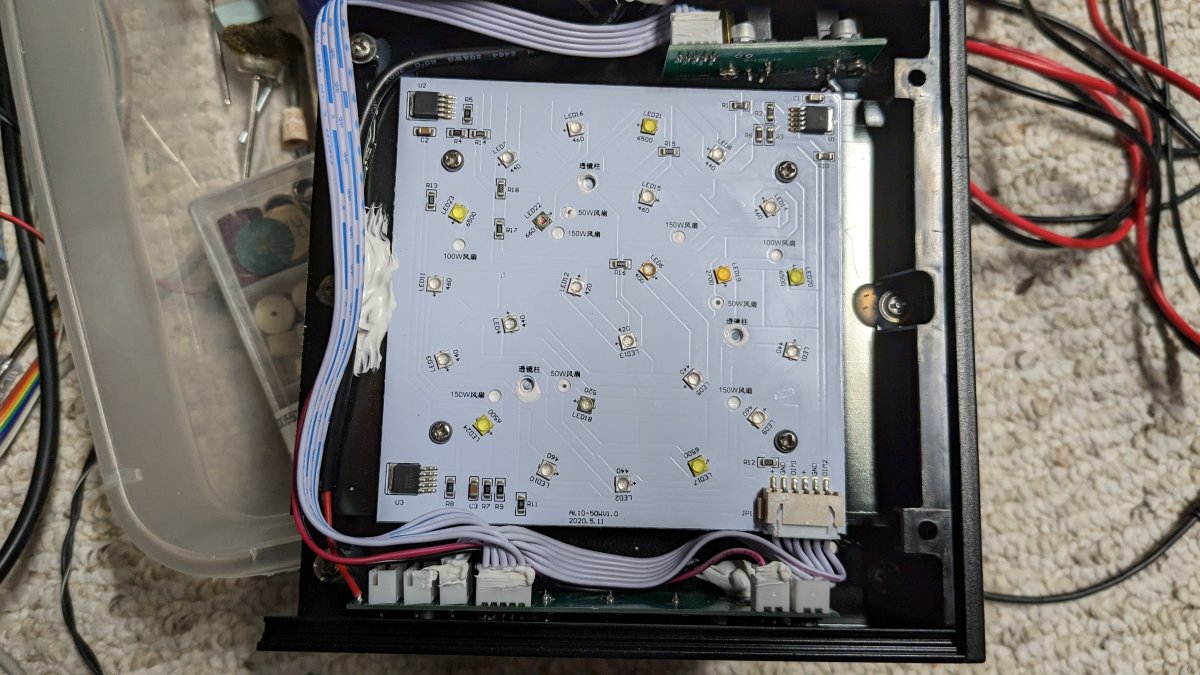
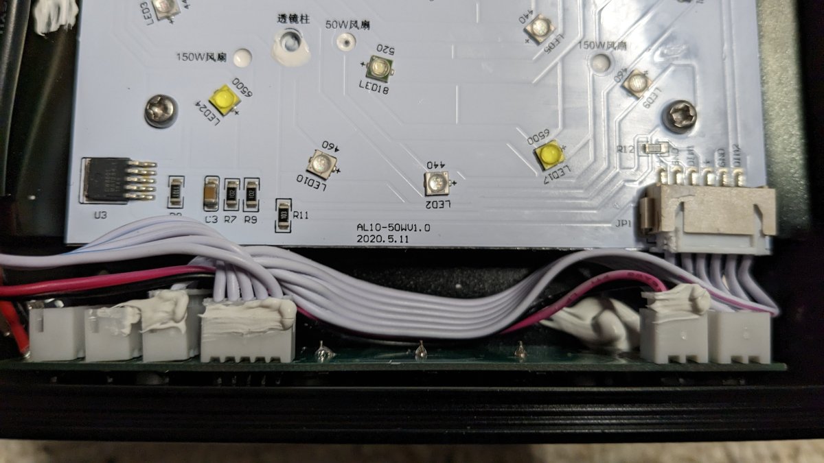
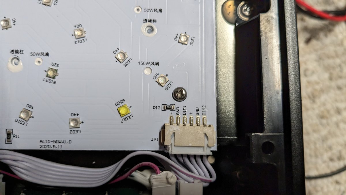
What I'm taking from here: the PWMB and PWMC from the signal input board come into the main board on the bottom, but it is not necessarily the same as the DIM1 and DIM2 signal that go to the lights.
 
Last edited:
OP
OP
S

Sral

Valuable Member
View Badges
Joined
May 2, 2022
Messages
1,006
Reaction score
976
Location
Germany
Rating - 0%
0   0   0
What I would test is step by step:
- we know that ReefPi outputs 10V PWM
- test that the audio jack has the right polarity of this signal
----> e.g. that the tip of the audio jack has the voltage and the jacket is GND
- connect the audio jack to the input board and measure all the pins corresponding to that jack on the backside with a multimeter and see if that voltage arrives on the board
 
Last edited:

bishoptf

Valuable Member
View Badges
Joined
Jan 1, 2019
Messages
1,344
Reaction score
1,722
Location
Missouri
Rating - 0%
0   0   0
@Sral Really appreciate you writing this up, I would have posted last night but had no idea, lol. I can take some closer pics and look under my magnifying lopes and pull the chip numbers off if that helps to get further clarification. So its working with the front panel, blue, white channels you can go up and down but doesn't work via 0-10v input. In fact if you disconnect that board the light will not come on, so it is looking for some input from that board to even come on.

The light input voltage coming in from the mains is 24v, looks like it uses pwm internally to change the intensity for each channel, 5%,20,40,60,80,100%. I am not sure how to troubleshoot that board, that is what I am attempting to do now, I get the voltages from backside of the board when the 3.5mm jack is plug in so I know the voltages are making it to the board but when I try to take a reading from the connector for each channel its always 0 and I believe that is my issue, the signal/voltage is not making it to the connector and thereby not going to the main board.

What I would test is step by step:
- we know that ReefPi outputs 10V PWM
- test that the audio jack has the right polarity of this signal
----> e.g. that the tip of the audio jack has the voltage and the jacket is GND
- connect the audio jack to the input board and measure all the pins corresponding to that jack on the backside with a multimeter and see if that voltage arrives on the board

Audio jack has the correct polarity, and have verified from the back of the board with a multimeter, although its not clear to me which should be ground vs tip and ring on the back side. I have done a continuity test and mapped them but they are not labeled so I am just assuming that is correct. Really gets down to that board I believe and what I should look for since it's odd that it also affects both channels, neither one is working maybe @theatrus has some suggestions, looking for someone that can help me troubleshoot that board.

My next idea is I have a Kessil light, I will make sure that it can control it just to be sure the circuit works but with my MM, I see it ramp up from .1v to 10v so looks like its working to me.

Update, just tested the setup on my kessil light and it works as expected, doesn't turn on until it hits 10% but ramps up and down through the range as expected so I at least verify that it is working as expected with a trs plug etc, both channels.
 
Last edited:

bishoptf

Valuable Member
View Badges
Joined
Jan 1, 2019
Messages
1,344
Reaction score
1,722
Location
Missouri
Rating - 0%
0   0   0
@Tom Bishop has some problems controling his Nicrew 50W lamp with ReefPi as descriobed in the main ReefPi thread here and here.

He built a 10V PWM source using the Adafruit Guide, which works as intended. This is connected to the lamps 0-10VDC control input with an audio jack as described here. However the lights do not react.

We have the input board:
InputBoard_front.jpg
InputBoard_back.jpg

1 is probably a regulator that provides the ICs with a nice voltage. Something like 3.3V or 5V, that will likely also be the PWM voltage
The two capacitors to the side are typical for this, one to stabilize the input voltage of the regulator, one to stabilize the output voltage of the regulator
2 is some IC that probably measures the input voltage and turns it into a corresponding PWM signal
3 is another IC, possibly some kind of fuse
4 and 5 are the input and output jacks. As you can see on the backside, some of the contacts are simply connected identical to the next, so it's probably just a nice way of giving another lamp the same signal without having to cut and solder an audio wire.

The white connector has 2 pins for PWM. If cou trace them on the board you will see that both connect to the IC number 2.

There are a whole bunch of resistors on the board. I wouldn't at all be surprised if some of them stepped down the input 10V to a nicely measureable 1-3V signal, as an IC made for 3.3-5V typically doesn't like 10V.

More pictures of the lamp:
I did some close up views under my eye loupes and here is what I think I see for each call out above:

1- lm317g NDTD, Terminal ADjuster Regulator - https://www.ti.com/lit/ds/symlink/lm317.pdf
2 and 3 I believe are the same chip, I cannot see any writing on chip 2, NCE55P05S, P-Channel Enhancement Mode Power MOSFET - http://ncepower.com/upload/cn/propdf/NCE55P05S.pdf
4 and 5 are input jacks

What I have so far...
 
OP
OP
S

Sral

Valuable Member
View Badges
Joined
May 2, 2022
Messages
1,006
Reaction score
976
Location
Germany
Rating - 0%
0   0   0
Great so far. Would be nice to have some more detailed shots from front and back to retrace some of the lines.

1 supplies a nice voltage with those 3 resistors next to it
2 and 3 I believe are not the same chip, otherwise they should have the same markings and similar pin usage, but the number 3 has all pins connected to the same line. If you look into the datasheet, that makes sense, as all 4 pins on that side are drains of the same MOSFET.
This looks either like a reverse polarity protection, OR like a cut-off switch. That's what you can use p-MOSFETs for. I'm also worried about that "PS" pin. No idea, but maybe that is the cut-off signal with which the main board can simpy turn off this input board.

Can you have a look in the manual or the menu, if there is any setting for this ?
 

bishoptf

Valuable Member
View Badges
Joined
Jan 1, 2019
Messages
1,344
Reaction score
1,722
Location
Missouri
Rating - 0%
0   0   0
Great so far. Would be nice to have some more detailed shots from front and back to retrace some of the lines.

1 supplies a nice voltage with those 3 resistors next to it
2 and 3 I believe are not the same chip, otherwise they should have the same markings and similar pin usage, but the number 3 has all pins connected to the same line. If you look into the datasheet, that makes sense, as all 4 pins on that side are drains of the same MOSFET.
This looks either like a reverse polarity protection, OR like a cut-off switch. That's what you can use p-MOSFETs for. I'm also worried about that "PS" pin. No idea, but maybe that is the cut-off signal with which the main board can simpy turn off this input board.

Can you have a look in the manual or the menu, if there is any setting for this ?
Yeah the manual is bare bones not much in the manual but high level useage etc.. I noticed the PS callout also and not sure if it means power supply or what, called out on the main board also. Here are some more pics:

PXL_20230117_183407168.jpg

PXL_20230117_183450807.jpg

PXL_20230117_183801235.jpg


I wouldnt mind removing the main board but it's not real clear how its held in there, looks to be soldered on the standoffs but that is just what it appears I do not see any screws holding it on.

I will say there is some spotty solder joints on the input board, one is really bad on one of the smd resistors, not sure if that would cause the issue but here is where I am seeing it:

PXL_20230117_183450807-a.jpg


Bad for even my standards, lol. :)
 

theatrus

Valuable Member
View Badges
Joined
Mar 26, 2016
Messages
1,950
Reaction score
3,351
Location
Sacramento, CA area
Rating - 0%
0   0   0
2 and 3 I believe are not the same chip, otherwise they should have the same markings and similar pin usage, but the number 3 has all pins connected to the same line. If you look into the datasheet, that makes sense, as all 4 pins on that side are drains of the same MOSFET.

Seconded, also one is Q1 (Q is common for transistor/mosfet) and one is U2 (common for any IC)


The bottom resistor was definetley bodged in after assembly. The top one probably got swapped with a different value at the same time.

I haven't traced it out fully, but checking what U2 is (the one near the bodged parts) again could be helpful. This board looks like it probably chops the +24V line, through Q1, through R11, and to the two PWM pins going out R9/R10. The bottom row is the gate drive for Q1 in some form.
 

bishoptf

Valuable Member
View Badges
Joined
Jan 1, 2019
Messages
1,344
Reaction score
1,722
Location
Missouri
Rating - 0%
0   0   0
Seconded, also one is Q1 (Q is common for transistor/mosfet) and one is U2 (common for any IC)


The bottom resistor was definetley bodged in after assembly. The top one probably got swapped with a different value at the same time.

I haven't traced it out fully, but checking what U2 is (the one near the bodged parts) again could be helpful. This board looks like it probably chops the +24V line, through Q1, through R11, and to the two PWM pins going out R9/R10. The bottom row is the gate drive for Q1 in some form.
Yeah not sure why they care about moving 24v from one light to another, I am using a trs plug so 24v is shorted to ground, but there is 24v on the board. Wish I understood how all this stuff fits together, but thanks @theatrus for chiming in, all I know is I have reef-pi spitting out 0-10v and the back of the board where the pins are attached I see the voltage but on the connector that goes to the main board I get 0v, so something is whack...:)
 

bishoptf

Valuable Member
View Badges
Joined
Jan 1, 2019
Messages
1,344
Reaction score
1,722
Location
Missouri
Rating - 0%
0   0   0
I have one of those cheapie microscope for looking at my smd work, I will see if I can get some better pics of the sections that shows more detail...will have to be after work but I will try to get some tonight.

Oh @theatrus I am in the process of building out a new nano, a 33g long tank, basically 48 x12x12, so long but shallow. I had this one nicrew and was going to add a couple more but you have anything that you are working on light wise that I may want to consider?
 
OP
OP
S

Sral

Valuable Member
View Badges
Joined
May 2, 2022
Messages
1,006
Reaction score
976
Location
Germany
Rating - 0%
0   0   0
Alright, some of the details are still hard to make out, but that's what I have so far:
InputBoard_front_2.jpg

InputBoard_back_2.jpg


PS connects to Pin 3 of the, I guess Microcontroller, over Resistor R18 in the top right. Its likely that this is the feedback signal to the main control board, that the board is connected. At least that would be my guess. That would however also imply that the microcontroller sends that signal back and therefore seems to work. Not absolutely sure though.

Pins 7 and 4 look like they are the PWM out pins, not sure on the pin 4 though.

Try Setting the ReefPi PWM signal to 100% before powering on the light, that should be a nice 10V DC signal without any PWm component that the circuti might dislike. Afterwards measure the voltage on R9 (PWMC), R10 (PWMB) and R18 (PS). Not sure though where you could find a GND to measure against, the best point might be to carefully use the back of that capacitor in the top left, where I marked GND.
 

bishoptf

Valuable Member
View Badges
Joined
Jan 1, 2019
Messages
1,344
Reaction score
1,722
Location
Missouri
Rating - 0%
0   0   0
Alright, some of the details are still hard to make out, but that's what I have so far:
InputBoard_front_2.jpg

InputBoard_back_2.jpg


PS connects to Pin 3 of the, I guess Microcontroller, over Resistor R18 in the top right. Its likely that this is the feedback signal to the main control board, that the board is connected. At least that would be my guess. That would however also imply that the microcontroller sends that signal back and therefore seems to work. Not absolutely sure though.

Pins 7 and 4 look like they are the PWM out pins, not sure on the pin 4 though.

Try Setting the ReefPi PWM signal to 100% before powering on the light, that should be a nice 10V DC signal without any PWm component that the circuti might dislike. Afterwards measure the voltage on R9 (PWMC), R10 (PWMB) and R18 (PS). Not sure though where you could find a GND to measure against, the best point might be to carefully use the back of that capacitor in the top left, where I marked GND.
Will do this later this evening, but I have done something similar, I took measurements from ground and pwmc and pwmb from the back of that connector and they were giving me 0v. The light also acts funny since what it should do is turn off if I have the levels set to 0, the light basically just stays the same no matter what voltage I have set on reef-pi.
 
OP
OP
S

Sral

Valuable Member
View Badges
Joined
May 2, 2022
Messages
1,006
Reaction score
976
Location
Germany
Rating - 0%
0   0   0
Good point, if input is 0V, how would the board know that you even have a connector attached ? I'm guessing that's what the many contacts on the audio jacks are for: some are probably just to detect whether a connector has been plugged in.
Another helpless test might be to connect another audio jack to the "OUT" connector and see if that makes a difference, test if both connectors are connected, or what happens when you plug in the signal at the other jack.
 

bishoptf

Valuable Member
View Badges
Joined
Jan 1, 2019
Messages
1,344
Reaction score
1,722
Location
Missouri
Rating - 0%
0   0   0
Good point, if input is 0V, how would the board know that you even have a connector attached ? I'm guessing that's what the many contacts on the audio jacks are for: some are probably just to detect whether a connector has been plugged in.
Another helpless test might be to connect another audio jack to the "OUT" connector and see if that makes a difference, test if both connectors are connected, or what happens when you plug in the signal at the other jack.
One thing I do know is that if you disconnect that input board from the main board the light will not turn on at all, fan spins up and the usually the light turns on but nothing happens when that input board is disconnected.
 

theatrus

Valuable Member
View Badges
Joined
Mar 26, 2016
Messages
1,950
Reaction score
3,351
Location
Sacramento, CA area
Rating - 0%
0   0   0
Good point, if input is 0V, how would the board know that you even have a connector attached ? I'm guessing that's what the many contacts on the audio jacks are for: some are probably just to detect whether a connector has been plugged in.
Another helpless test might be to connect another audio jack to the "OUT" connector and see if that makes a difference, test if both connectors are connected, or what happens when you plug in the signal at the other jack.
Often with audio jacks, you’ll find two contacts touch on the same ring, so you can detect a plug in if those two contacts are now shorted. Same goes for some power jacks - two different pins and wipers make contact with the outer part of the barrel.

it’s probably also helpful to plug in a plug, with nothing powered, and check which pins have continuity to each other and to the board solder points.
 

bishoptf

Valuable Member
View Badges
Joined
Jan 1, 2019
Messages
1,344
Reaction score
1,722
Location
Missouri
Rating - 0%
0   0   0
I have documented the continuity with the input of a 3pin trs plug and documented on the back pins, R-ring, G-Ground, T-Tip. Unmarked pins have no continuity when testing the plug.

Red - Ground
Ring- White
Tip - Yellow
PXL_20230117_183407168-annotated.jpg
 

bishoptf

Valuable Member
View Badges
Joined
Jan 1, 2019
Messages
1,344
Reaction score
1,722
Location
Missouri
Rating - 0%
0   0   0
Here are some up close pics, here is the

over all layout:
PXL_20230118_171542472.jpg


Each little section of the above:
20230118_105550.jpg

20230118_105605.jpg

20230118_105628.jpg

20230118_105636.jpg

20230118_105656.jpg

20230118_105715.jpg

20230118_105733.jpg


I tried to have some overlap so you can see where it is on the board. Hopefully this is clear enough, again refer to the top pic for orientation.
 

theatrus

Valuable Member
View Badges
Joined
Mar 26, 2016
Messages
1,950
Reaction score
3,351
Location
Sacramento, CA area
Rating - 0%
0   0   0
Thanks for all the pictures :)

Does U2 have no markings whatsoever? Sometimes looking at extreme off angles with light helps bring out any faded markings, and sometimes manufacturers scrub them to make this whole process more difficult (though it doesn't look like its sanded or lasered off).
 

bishoptf

Valuable Member
View Badges
Joined
Jan 1, 2019
Messages
1,344
Reaction score
1,722
Location
Missouri
Rating - 0%
0   0   0
Thanks for all the pictures :)

Does U2 have no markings whatsoever? Sometimes looking at extreme off angles with light helps bring out any faded markings, and sometimes manufacturers scrub them to make this whole process more difficult (though it doesn't look like its sanded or lasered off).
I've looked under the scope and my loupes and I cant see anything on U2, everything else has markings though faint. I have purchased another unit from ebay, reluctant to also crack it open but maybe I will and see if the board is different or has better markings, really stinks since the light works manually but that does me no good...
 

theatrus

Valuable Member
View Badges
Joined
Mar 26, 2016
Messages
1,950
Reaction score
3,351
Location
Sacramento, CA area
Rating - 0%
0   0   0
Bummer. Its probably not critical but it probably would help understanding. FWIW, its likely a small micro controller (one ADC, one PWM), but we can probably guess the overall function from that. Will take a look later and see if I can make out something and get the rest of the brain trust theorizing.
 

bishoptf

Valuable Member
View Badges
Joined
Jan 1, 2019
Messages
1,344
Reaction score
1,722
Location
Missouri
Rating - 0%
0   0   0
Bummer. Its probably not critical but it probably would help understanding. FWIW, its likely a small micro controller (one ADC, one PWM), but we can probably guess the overall function from that. Will take a look later and see if I can make out something and get the rest of the brain trust theorizing.
I tried scrubbing it with some alcohol but I do not see any markings on it at all.
 

More than just hot air: Is there a Pufferfish in your aquarium?

  • There is currently a pufferfish in my aquarium.

    Votes: 30 18.2%
  • There is not currently a pufferfish in my aquarium, but I have kept one in the past.

    Votes: 27 16.4%
  • There has never been a pufferfish in my aquarium, but I plan to keep one in the future.

    Votes: 31 18.8%
  • I have no plans to keep a pufferfish in my aquarium.

    Votes: 69 41.8%
  • Other.

    Votes: 8 4.8%
Back
Top