RODI Pressure Switch and Auto Flush Problem

danmr

New Member
View Badges
Joined
Nov 8, 2019
Messages
12
Reaction score
8
Rating - 0%
0   0   0
Looking for some help with my recently upgraded my RODI system. The info is below (poorly organized).

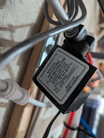
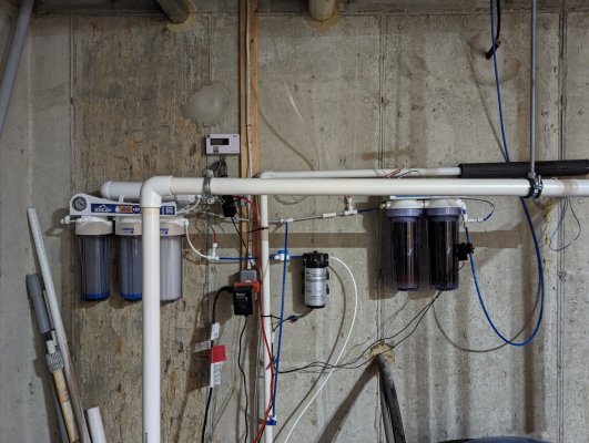
I started with an Icecap 4 stage. About a month ago I added a pump and pressure switch. Last week, I added a 2 stage DI and auto flush. The system doesn't seem to be working correctly. Attached is a diagram of how it is currently hooked up. In this configuration, the auto flush stays partially open when there is no demand for water (very slow waste water flow). I assume it shouldn't do that.

I initially wanted to put the pressure switch in the highlighted area so the pump is turns on when there is a demand for drinking water. However, when I had it there it turned on randomly. This happened before and after the auto flush valve was installed.

I should also mention that if I unplug the transformer and turn of the water supply to the unit, the pressure drops to zero over time. Shouldn't the system stay pressurized? Based on my limited knowledge of how these systems work, everything together points to a leak somewhere. I haven't seen any signs of a leak though.

Lastly, the RO doesn't seem to be performing as well as it should. I have approx. 100 TDS going in and it enters the DI at 13 TDS. The system is only 3 months old, so I would think the membrane should still be performing near spec (98% rejection rate).

Does anyone see anything incorrect with the configuration or have any suggestions?

PXL_20240401_133959208_.jpg
 

EeyoreIsMySpiritAnimal

Just another girl who likes fish
View Badges
Joined
May 14, 2019
Messages
13,427
Reaction score
19,949
Location
Spring, Texas
Rating - 0%
0   0   0
First thing I'd check: are you sure the 2 lines coming out of the membrane are in the correct spots?
Can you post a photo of the auto flush? Are you sure it's sized properly (should match the gpd of the membrane)?
When you say "turn off the water supply", are you completely disconnecting the unit from the faucet? If so, then it will not be pressurized.
Is the drawing above the actual placement of everything ( pump higher than intake, membrane higher than stages 1&2, etc? (I'm not sure there's anything wrong with this, just wanting a clearer picture.

@Buckeye Hydro - what are your thoughts?
 
OP
OP
D

danmr

New Member
View Badges
Joined
Nov 8, 2019
Messages
12
Reaction score
8
Rating - 0%
0   0   0
First thing I'd check: are you sure the 2 lines coming out of the membrane are in the correct spots?
Can you post a photo of the auto flush? Are you sure it's sized properly (should match the gpd of the membrane)?
When you say "turn off the water supply", are you completely disconnecting the unit from the faucet? If so, then it will not be pressurized.
Is the drawing above the actual placement of everything ( pump higher than intake, membrane higher than stages 1&2, etc? (I'm not sure there's anything wrong with this, just wanting a clearer picture.

@Buckeye Hydro - what are your thoughts?
Thanks for the reply. I didn't change what the lines coming out connect to (I tried to only disconnect one thing at a time), so I think they are in the correct spot. The only one that I'm not fully confident in is from stage 2 to stage 3. What is now stage 3 was originally DI.

The autoflush is 800 ml/min which I selected based on the 100 GPD single membrane unit using BRS info. That matches the original flush valve the was replaced.

Turn off water supply = close valve, not disconnect

The drawing was not meant to reflect relative elevation differences, but its not far off except the 'out' does go up (around 4ft. Hpressure). Attached are more photos (disregard the sloppy wiring - I'll clean it up once its working).
 

Attachments

  • PXL_20240401_144557337.jpg
    PXL_20240401_144557337.jpg
    127.2 KB · Views: 25
  • PXL_20240401_144527457.jpg
    PXL_20240401_144527457.jpg
    268.1 KB · Views: 27
OP
OP
D

danmr

New Member
View Badges
Joined
Nov 8, 2019
Messages
12
Reaction score
8
Rating - 0%
0   0   0
Wait... your questions made me take a step back and look at this again. I think I found my error. The feed comes from a well bladder tank. I need a check valve to stop water flowing backwards through the system. Probably also explains why I reduced membrane performance so quickly, as water would have been frequently running in reverse to equalize pressure. The only thing I haven't figured out is why pressure dropped to zero instead of the lower limit of the well pressure switch, but maybe I got that wrong. I'll put the check in and see what happens.

Thank you!
 

Buckeye Hydro

Valuable Member
View Badges
Joined
Dec 17, 2013
Messages
1,388
Reaction score
936
Location
Ohio
Rating - 0%
0   0   0
Some comments:
  • The location of your pump could be improved. Should be after the prefilters.
  • If you are on well water you have no chlorine in your water... so why are you using two carbon blocks?
  • You should have a check valve on the permeate tube right after it comes out of the membrane.
  • You should have a check valve such that water can't come back from the pressure tank and make it to the DI
  • Your flush valve is a normally closed solenoid, except for the oriface through the FR.
  • I see nothing on your system to stop the flow of water - you should have a solenoid valve on the feedwater tube.
 
OP
OP
D

danmr

New Member
View Badges
Joined
Nov 8, 2019
Messages
12
Reaction score
8
Rating - 0%
0   0   0
Some comments:
  • The location of your pump could be improved. Should be after the prefilters.
  • If you are on well water you have no chlorine in your water... so why are you using two carbon blocks?
  • You should have a check valve on the permeate tube right after it comes out of the membrane.
  • You should have a check valve such that water can't come back from the pressure tank and make it to the DI
  • Your flush valve is a normally closed solenoid, except for the oriface through the FR.
  • I see nothing on your system to stop the flow of water - you should have a solenoid valve on the feedwater tube.
Thanks for the information. Please see follow up below. I am definitely not questioning your comments, just interested to understand better.
  • The location of your pump could be improved. Should be after the prefilters.
    • I don't understand this one but I would like to. The way I am thinking of it, the pump is only there to increase pressure differential. As long as that happens before the membrane, I don't understand why it matters where. Granted, if it was located after the sediment it would be provided some protection from particles. Is this the benefit to having it after the prefilters?
  • If you are on well water you have no chlorine in your water... so why are you using two carbon blocks?
    • I actually plan to run 2 sediments and 1 carbon. I have am only using 2 carbons currently because that's what I had (I was going to leave it empty for the time being but didn't know if that would create a problem). Really, the only reason I added the double DI was because it was on sale cheaper than the single.
  • You should have a check valve on the permeate tube right after it comes out of the membrane.
    • I would think this should be after the drinking water tap to prevent backflow from DI? If I open the drinking water valve with the check before the drinking water tap, the DI canisters start to empty.
  • You should have a check valve such that water can't come back from the pressure tank and make it to the DI
    • Is this the drinking water pressure tank? If so, I don't have that installed yet. The branch is just terminated with a valve currently. That said, I don't understand why a check valve is beneficial there, since there's one downstream of the drinking water tap.
  • Your flush valve is a normally closed solenoid, except for the oriface through the FR.
    • Sorry, what is FR?
  • I see nothing on your system to stop the flow of water - you should have a solenoid valve on the feedwater tube.
    • I have a solenoid valve on the 'out' side (at the RODI reservoir). Locating it on the feedwater would have avoided the need for a check valve (and my original question), but the solenoid connects to my hydros system further downstream to run the schedule to make the water. Is there an issue having the valve at the reservoir provided I have a check on the feedwater?
 

Buckeye Hydro

Valuable Member
View Badges
Joined
Dec 17, 2013
Messages
1,388
Reaction score
936
Location
Ohio
Rating - 0%
0   0   0
The weakest component on your system in terms of ability to withstand high pressure is your clear housings. Raise the pressure after these housings and they won't see the high pressure.

Re the check valves - take a look at the instructions on our website for the Reef Residential RODI

FR = Flow Restrictor

You need a solenoid on the feedwater so that when your reservoirs are full the pump turns off AND the water flow through the system (including your concentrate) stops flowing
 

Looking for the spotlight: Do your fish notice the lighting in your reef tank?

  • My fish seem to regularly respond to the lighting in my reef tank.

    Votes: 61 74.4%
  • My fish seem to occasionally respond to the lighting in my tank.

    Votes: 10 12.2%
  • My fish seem to rarely respond to the lighting in my tank.

    Votes: 6 7.3%
  • My fish seem to never respond to the lighting in my tank.

    Votes: 0 0.0%
  • I don’t pay enough attention to my fish to notice if they respond to the lighting.

    Votes: 2 2.4%
  • I don’t have any fish in my tank.

    Votes: 2 2.4%
  • Other.

    Votes: 1 1.2%
Back
Top