Suggestions for flow in a new 80 Gallon Shallow Reef Build

Users Who Are Viewing This Thread (Total: 1, Members: 0, Guests: 1)

Spdjnky

Well-Known Member
View Badges
Joined
Dec 31, 2017
Messages
546
Reaction score
161
Location
Schenectady
Rating - 0%
0   0   0
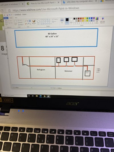
I am restarting my reef new after Sterilizing everything due not quarantining. I am making some changes in my plumbing and I am looking for any comments and or suggestions on the best way to go.
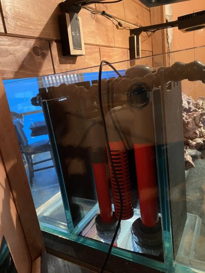
I am running the Triton Method and I have modified my sump. At first I had allot of problems with algae getting to the return pump came to find that the biggest problem was the Sea Lettuce once I took that out didn't have to many problems once I put the plate in you can see before the Skimmer Section.
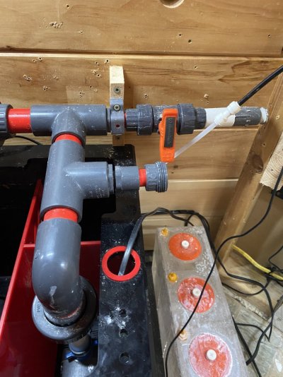
I am using a Syncra Silent Sicce 5.0 pump (1321GPH) That gives me 550 GPH at the flow sensor located where the return line goes to the Tank.
I will be using a Red Sea Reef Wave 25 on the far end of my Peninsula style tank.
I was using a small pump that I could just fit next to my Skimmer pump. I am looking to go to a manifold to run my Carbon and GFO reactors and I would like to plumb in another Reactor that I could use when I wanted to run a sediment filter when I want to. Right now I just hang one with a small pump if I want to polish water.
That being said if you can understand me what would be the right size return pump if I go that way and can I get enough Flow from my 2 return nozzles on the overflow side of the tank for a Mixed Reef.


addVzFXJRmimjgHV77xmig.jpg %9wGzm21R6iaPMjYYHWPmw.jpg %hK3nrOATfGywlKRO6ZtfA.jpg rbwqEo8vRJmQxXE01GZG3w.jpg l52ozaCMQ8OToCWTphL1KA.jpg
 
OP
OP
Spdjnky

Spdjnky

Well-Known Member
View Badges
Joined
Dec 31, 2017
Messages
546
Reaction score
161
Location
Schenectady
Rating - 0%
0   0   0
The pictures are all mixed up but hope you can see what I have to work with. I have made changes to my apex from the last pic

3b55zGgYR4+i2i%uXAANEg.jpg
 

cloakerpoked

Well-Known Member
View Badges
Joined
Mar 13, 2009
Messages
553
Reaction score
31
Location
Fort Mill, SC
Rating - 0%
0   0   0
Really nice setup you have there. I appreciate seeing people who take the time to lay out the sump area in such a careful way.

As far as suggestions for pumps, I don't have any, because a lot of that is going to depend on your budget, end goals for flow, energy consumption, etc. However, I do have a few principles that I can explain when looking into adding a manifold like you're talking about.

So, based on what you're describing (if I'm understanding you properly), you'll presumably have a 4 port manifold, 3 that go to various media reactors and one that goes to the tank. I'm also going to assume that you plan to add ball valves on all of them, so you can adjust flow rates to each line separately. I'll also suggest adding a 5 line, which is a direct return to the sump. This can be really helpful to alleviate extra pressure, since not all pumps run their best when they're being metered by ball valves. It is normally preferable to send that excess flow back to the sump and run the pump at 100%, rather than having the restriction built up in your collective lines be throttling the pump back.

There are a lot of losses in this kind of thing, and an engineer might be able to do the calculations, but we (or at least I) can't, even with particulars. The head loss you'll experience will depend on each individual pathway (i.e. how many 90 degree angles, distance, diameter of the pipe, relative height from the pump, etc). Suffice it to say it isn't 100% of the pump's specs.

Assuming that you're planning your manifold with all outputs at a 90 degree angle to the main line (usually having a cap at the end) that will at least equalize (relatively) the potential flow rate through each one. Designing the flow pipe from the pump to the manifold (and the manifold body) larger than individual lines helps preserve flow. In other words, using 1 1/4" pipe and then stepping down to 3/4" for each line in the manifold gives you a natural increase of pressure in the smaller pipe, which helps preserve head height.

You probably aren't looking for fast flow through your media reactors, so they may not add a ton to what you already have going on, although the general inefficiencies of the manifold probably will add a significant amount of head loss. You can compensate for that one of two ways: Getting a pump with higher flow, or getting a pump with higher head pressure. I'd check the specs of the pumps that you think about. Pumps with higher head pressures (i.e. they lose less to gravity) will probably tend to operate better for this application. I don't know enough about the new adjustable flow DC pumps, but that could be really easy to use if they are designed to run under higher pressures, because you could literally adjust the sending pressure of the pump to get the rate you need at each point. As long as you have ball valves on each manifold branch, that won't be impossible no matter what, but you won't be using more electricity or mileage on the pump. That would also take away the need for the extra line going back to the sump.

Just keep in mind that whatever you do, you'll lose a percentage of the flow rate, and it will be significant in a manifold (not usually 50%, but also not 5%). You can't just add up 100gph for each reactor (x3) and a return with 2 branches, so I want 500gph on each one, that adds up to 1300gph and then buy that pump. You'll have to go bigger. How much bigger depends on the design of the system, distance, pathway and diameter of each pipe, and the design of the pump (high flow rate vs. high head pressure).

Good luck.
 
OP
OP
Spdjnky

Spdjnky

Well-Known Member
View Badges
Joined
Dec 31, 2017
Messages
546
Reaction score
161
Location
Schenectady
Rating - 0%
0   0   0
Thanks for all your input. As you can see from this picture I already have my plumbing in the back where I can add a 1/2" line for my Carbon and GFO reactors. In the front the line going to the 1" "T" was where I would hook my fill line in when doing water changes. I don't want to use it that way anymore. I plan on using it for a reactor that I can run a sediment filter in when I need to polish water. What I am trying to find out now is how much GPH I can run with my overflow that is Durso Style with a 1" return line and a 1 1/2" Drain. Thats why I was thinking DC because that way I could dial it in to what I needed but that goes back to not really knowing. Because I am running the Triton Method with the refugium first in line in the sump.
 

Attachments

  • 0t%SUqDaQyS55nFtid3Otw.jpg
    0t%SUqDaQyS55nFtid3Otw.jpg
    200.9 KB · Views: 98

cloakerpoked

Well-Known Member
View Badges
Joined
Mar 13, 2009
Messages
553
Reaction score
31
Location
Fort Mill, SC
Rating - 0%
0   0   0
Do you only have one drain hole in the display? You can run more flow when you run one under syphon and then the durso style as the backup or overflow. This can be quieter but requires more dialing.
 
OP
OP
Spdjnky

Spdjnky

Well-Known Member
View Badges
Joined
Dec 31, 2017
Messages
546
Reaction score
161
Location
Schenectady
Rating - 0%
0   0   0
Only have the one drain and it runs quiet at 550 GPH where my flow sensor is and that is about 3' below the water surface. So whats that maybe 400 GPH
 

Attachments

  • Zuno7h7KSpunMAaSzEeKbw.jpg
    Zuno7h7KSpunMAaSzEeKbw.jpg
    189.1 KB · Views: 83
OP
OP
Spdjnky

Spdjnky

Well-Known Member
View Badges
Joined
Dec 31, 2017
Messages
546
Reaction score
161
Location
Schenectady
Rating - 0%
0   0   0
Thats just a cover over the glass overflow box. I have never liked how they did it I am having a new one made that will go just above the top rim of the aquarium and a cover to go over it so the Algae won't grow in the overflow box.
 
OP
OP
Spdjnky

Spdjnky

Well-Known Member
View Badges
Joined
Dec 31, 2017
Messages
546
Reaction score
161
Location
Schenectady
Rating - 0%
0   0   0
According to what Durso has on there web site the 1 1/2" Drain should be able to handle 1000 to 1500 GPH. but it all depends on the spacing and the size of the teeth. And that brings me right back to the same question how much flow through the refugium and where I arrive at the right flow rate. That I am still confused abouit.
 

cloakerpoked

Well-Known Member
View Badges
Joined
Mar 13, 2009
Messages
553
Reaction score
31
Location
Fort Mill, SC
Rating - 0%
0   0   0
Not sure what you're really after, but you don't need a ton of flow from the refugium to the display, unless you're counting on that flow for the coral.

You want enough flow to have the water height where you want it, but you can usually use the overflow configuration to manipulate that. An MP40 or something equivalent would get you the flow in the display tank that you'd need (if you needed higher flow rate) without needing to shove it all through your sump. Since the hypothetical flow rate through the reactors is much slower, as long as the rate of turn over through the sump matches the flow rate through the reactors, you're still filtering the overall water volume because the limiting factor would still the flow through the reactor, not flow through the sump.

Theoretically, any flow rate through the tank that is higher than the rate through the reactor achieves that purpose, so at that point, it's really mostly a question of how much flow you want, not how much you need. If you're happy with the rate as it is now, I wouldn't really be trying to increase it unless you were trying to totally avoid powerheads.

Slower flow rates through the sump have the added benefit of keeping the microbubbles from the protein skimmer from being sucked into the display tank.
 
OP
OP
Spdjnky

Spdjnky

Well-Known Member
View Badges
Joined
Dec 31, 2017
Messages
546
Reaction score
161
Location
Schenectady
Rating - 0%
0   0   0
Correct me if I am wrong but seeing as I am running Triton I should have 800 GPH running through the sump. That's all I am trying to get close to right. With what I have right now I can have 550 GPH 3 feet below where it enters my Display. I could do a test and get the exact GPH but I don't think that's needed. When I plumb my reactors in the pump I have now won't be enough. I know the Reactors don't require allot of GPH but adding them in to the system will reduce my GPH at the Display even more than the GPH they need.
So my thinking is go with a DC return Pump that is a little more than I need to run the reactors and give me around 800 GPH at the Display. Just have to make my mind up on the right one and to tell the truth I think I am going to give the

Jebao DCP pump a try but I'm still not sure witch one.


cloakerpoked

Well-Known Member
View Badges
Joined
Mar 13, 2009
Messages
553
Reaction score
31
Location
Fort Mill, SC
Rating - 0%
0   0   0
Well, their recommendations are 10x system volume, which is probably greater than your display tank alone. You may want more like 1000 GPH total to meet that recommendation, so I'd agree with your 800 GPH estimation to the display. That leaves 100 GPH through each reactor (but I'd check the specs on them to follow the recommended flow rates...each ones is a little different.)

For your current pump, the Flow at 0' Head is 1300 GPH (rounding numbers) and max head is 12.6' but the drop off between those numbers is somewhat different for each pump. Converting to metric, your flow rate is roughly 2080 liters per hour. Based on the spec chart for the Sicce 5.0 that's about 2.6 meters (or 8.5 feet). That means that the current pathway your water travels to the tank is the equivalent of 8.5 feet of head pressure for that particular pump. Once you open those gate valves in the manifold, you'll get a drop in pressure, but this at least gives us a starting point for a pump recommendation, assuming that you're going to change out the pump, but not the plumbing between the pump and the tank.

If it was possible to put in the reactors, dial them into your planned flow rates, and then measure the output, we could use the same spec chart to calculate the estimated head pressure for the Sicce Pump at the tank with the reactors operating. Then we reverse engineer that backwards, and find a pump that has about 800 GPH at that particular head pressure.

This isn't perfect science, but it at least makes sense to me.

Without opening the gate valves to 100GPH (or whatever operational flow rate you plan to use) we really can't know for sure what the head pressure is at the tank, so we're guessing how big of a pump you'll need.
 
OP
OP
Spdjnky

Spdjnky

Well-Known Member
View Badges
Joined
Dec 31, 2017
Messages
546
Reaction score
161
Location
Schenectady
Rating - 0%
0   0   0
Well thank you but I got to tell you the truth your math and numbers has me lost I am just not that good at that but I am pretty good at the plumbing which I have done myself and I'm not really sure if where I have it to plumb the reactors in now is even the right place but is there a right place that I'm not really sure of. If I go with a DC pump that is larger then I need then I could dial that in and not run it at 100%. But then different pumps are rated for different Head Heights and what is the difference between that and GPH ? I am pretty sure then I will go with the Jebao DCP pump it's a budget thing I am spending a lot more money than I had planned on so it's a bit of a gamble that it will serve the purpose but I have heard some good things from other guys about them worth a try.
I'm in the process now rearranging everything apex included trying to figure out better wire management then I had the last time always a pain after take the pumps out to clean them.
 

cloakerpoked

Well-Known Member
View Badges
Joined
Mar 13, 2009
Messages
553
Reaction score
31
Location
Fort Mill, SC
Rating - 0%
0   0   0
The best way to plumb your manifold is in series. That would mean that your pump would go straight in to the manifold and end with a cap at the end. All branches of the manifold then come out of the manifold in the same general area (maybe 6-12 inches apart). This comes close to equalizing the pressure in each line. Your configuration appears to have branches at different places, which will put inconsistent pressure in each branch. In the configuration above, each line potentially gets about 25% of the available flow from the pump. Closing one valve all the way "donates" its flow to the remaining three, and you get 33%. Closing both reactor valves 1/2 way "donates" that flow to the display tank line. There are inefficiencies to the math there, so it will never add up to 100% of the flow coming out of the pump itself, but hopefully it at least illustrates the concept. On the other hand, if the display tank line came straight out of the manifold, it would get way more than 25%, because the water would prefer to keep moving in a straight line (Newtonian physics and all that) rather than backing up to go into the reactor lines. This is also the reason why using 2 - 45 degree pipes will add to flow rate, verses using a 90 degree elbow. The smoother the curve, the less friction, and reduction of flow. Your design appears to go straight to a T, with the reactor spaces upstream. That T is going to put back pressure in the line, which will probably give you enough for the reactors. However, that design is also a major reason why a pump rated for 1300 GPH is only putting out 500 at the tank.
Screen Shot 2021-04-01 at 12.53.13 PM.png


I'd definitely put a valve on each branch of the manifold. Preferably with a union after it, that way you can tie in to it easily. Closing the gate valve/ball valve all the way allows you to change the media in the reactor. (it also puts more pressure/flow into the remaining open lines). Closing the valve partway restricts flow on that branch, which adds to the pressure in the remaining branches.

Head Pressure: The amount of pressure the pump has to push water through a pipe. It is the theoretical number at which the pump can no longer overcome gravity.

Flow Rate: How many gallons per hour move through the pipe.

There are some pumps with low head pressure. They move a lot of water, but can't push it hard. (think Vortech). There are other pumps that have really high head pressure but have a very low flow rate. They might top out at 100 gph, but can push the water 30 feet up in the air.

So, it is possible that you could hook up a 3,000 gph pump to your plumbing that still wouldn't get you the flow you want. It is also possible that you could find one with 1500 gph that would get you the flow you want.

As a general rule for most aquarium pumps, it will decline slowly at first, but once the pump gets close to its max head pressure, you will get a trickle of water.
 
OP
OP
Spdjnky

Spdjnky

Well-Known Member
View Badges
Joined
Dec 31, 2017
Messages
546
Reaction score
161
Location
Schenectady
Rating - 0%
0   0   0
yea I agree with your diagram except why do you show the line going nowhere under the display.So I have 3 schedule 80 T's that I will plumb in and at the same time take the 2 T's out coming from the pump and replace with a 90 elbow. I will put 1/2" Ball valves after the T and run 2 BRS Reactors for Carbon and GFO . The extra reactor will be there to use with a sediment filter when I want to polish the water. So with changing to that what would you recommend for a DC return pump as far as size?
 
Last edited:
OP
OP
Spdjnky

Spdjnky

Well-Known Member
View Badges
Joined
Dec 31, 2017
Messages
546
Reaction score
161
Location
Schenectady
Rating - 0%
0   0   0
Okay I just used the Paint Program for the fist time so my diagram could be better but I hope a least it shows how I plan on redoing my plumbing. I will run BRS Reactors with there Silicone tubing for the feed and discharge back to the sump.
 

Attachments

  • 63hu%rP+QRSFZ4j4Kud3tg.jpg
    63hu%rP+QRSFZ4j4Kud3tg.jpg
    173.9 KB · Views: 72
OP
OP
Spdjnky

Spdjnky

Well-Known Member
View Badges
Joined
Dec 31, 2017
Messages
546
Reaction score
161
Location
Schenectady
Rating - 0%
0   0   0
It goes through a double 45 to get it to the 90 that lines up with my overflow.

xqb4e3fxTu6Oe5ZugdQztA.jpg xH7mOSoHT0uXjIwt+knd9A.jpg J9CMdcdgTviTAhADiZXUWA.jpg
 

cloakerpoked

Well-Known Member
View Badges
Joined
Mar 13, 2009
Messages
553
Reaction score
31
Location
Fort Mill, SC
Rating - 0%
0   0   0
If that straight line goes to the return, you won't have a lot of pressure coming out of the manifold. That may not matter, since you're not looking for a lot, but it is something to think about. You do have that ball valve, so you could always close it partway, and that would add pressure in the manifold.
 

Reefing threads: Do you wear gear from reef brands?

  • I wear reef gear everywhere.

    Votes: 13 22.0%
  • I wear reef gear primarily at fish events and my LFS.

    Votes: 2 3.4%
  • I wear reef gear primarily for water changes and tank maintenance.

    Votes: 0 0.0%
  • I wear reef gear primarily to relax where I live.

    Votes: 7 11.9%
  • I don’t wear gear from reef brands.

    Votes: 32 54.2%
  • Other.

    Votes: 5 8.5%
Back
Top