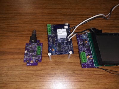
theatrus' "Perfect Temperature Controller"

mnl

New Member
View Badges
Joined
May 20, 2019
Messages
16
Reaction score
23
Rating - 0%
0   0   0
This is pretty intriguing, as long as the monitor doesn't end up sending an inhibit signal to both heater control loops simultaneously, which requires coordination between the heater elements as well. With simple logic, this could be avoided, but if we are using a simple logic signaling all it takes is a stray salt crystal to pull the inhibit or run line up or down and ruin our day.

I was thinking along the line of a simple but robust signal line. Use a latching relay double pole in the monitor. Those are generally very good about not being able to get caught between states. Then make the signal 20mA at 12V. You can use the second pole to drive a simple logic circuit so that the monitor just has to generate a pulse to switch. It doesn’t even need to know which heater is active, therefore it can’t forget. It’s action is to click the relay which changes the sides. Then just pay attention to signal separation and potentially use conformal coat on the boards. RTV around the base of connectors also helps keep the bad stuff out. Each heater module would have an independent power supply, the monitor would have no power supply, but would be fed from the two heater supplies diode OR’d together.

I have always used the two coil latching relays. I think there are single coil ballpoint pen types out there that change state with each pulse. I have no idea if they are considered as reliable.
 

mnl

New Member
View Badges
Joined
May 20, 2019
Messages
16
Reaction score
23
Rating - 0%
0   0   0
Initially I was planning on using a utility CAN interface to provide communications; if we want something with more intelligence in the path this is an option to use as its ready to use multi-master bus.

I freely admit to not being up on the latest bus and comm technology, but when I hear words like ”multi-master” my high reliability side goes running for cover. I don’t know how to test things like that to demonstrate that it cannot hang and then hang other things.

I am a big believer in serial clock and data. From a functional level the temperature controller needs one command, set the temperature. there will be a few others for housekeeping, but that is the mission critical one. An eight bit op code, seven bits of parameter, and a parity bit. I would think dividing up the limited temperature range by seven bit would be worlds. There would also be a couple of commands to get status, whatever is acting as master would send a status request and the unit would clock out its data, say one message for programmed temperature, one for actual temperature, and one for status. The command would go into a memory mapped location that the microcontroller would poll. It would never have to wait for anything, and it would never need a command unless someone wanted a slightly different tempremature. Status word could include a valid command count, parity flag, and error count. Set the default program temperature for something reasonable like 25.5C and have a watch dog timer that will kick the micro if for some reason it does hang.

The one thing the master should not be able to do it initiate a controller side switch autonomously. That is the sole purview of the monitor module with its independent temperature monitor.

Nominal control flow would be something like, master requests status to confirm unit is running. If it’s off, the request will time out and the master will go to the other side. Of course the master should remember which side is active, but it never hurts to check. Master sends command to program temperature. Master requests status word, checks no parity flag and command counter increments, master requests program temperature value and confirms correct value was set. Master can then monitor as required.

At no time does the device running the mission critical application wait, it is always running its control loop. The monitor should not also include the master function for the same reason. It should never be waiting.
 
OP
OP
theatrus

theatrus

Valuable Member
View Badges
Joined
Mar 26, 2016
Messages
1,973
Reaction score
3,363
Location
Sacramento, CA area
Rating - 0%
0   0   0
I was thinking along the line of a simple but robust signal line. Use a latching relay double pole in the monitor. Those are generally very good about not being able to get caught between states. Then make the signal 20mA at 12V. You can use the second pole to drive a simple logic circuit so that the monitor just has to generate a pulse to switch. It doesn’t even need to know which heater is active, therefore it can’t forget. It’s action is to click the relay which changes the sides. Then just pay attention to signal separation and potentially use conformal coat on the boards. RTV around the base of connectors also helps keep the bad stuff out. Each heater module would have an independent power supply, the monitor would have no power supply, but would be fed from the two heater supplies diode OR’d together.

Sounds reasonable, and conformal coating of the boards is a must. I've started doing that for everything myself after seeing the failure modes to some of my early LED lighting setups where the salt spray on the surface can sit undisturbed for years, but the second it soaks into the FR4 with some water all hell breaks loose and the entire substrate becomes conductive.
 
OP
OP
theatrus

theatrus

Valuable Member
View Badges
Joined
Mar 26, 2016
Messages
1,973
Reaction score
3,363
Location
Sacramento, CA area
Rating - 0%
0   0   0
I freely admit to not being up on the latest bus and comm technology, but when I hear words like ”multi-master” my high reliability side goes running for cover. I don’t know how to test things like that to demonstrate that it cannot hang and then hang other things.

Part of the strategy for CAN is its already fault tolerant in an automotive control world. Looking at one particular transceiver IC, it already implements two useful properties:


The MCP2561/2 device prevents two conditions:
• Permanent dominant condition on TXD
• Permanent dominant condition on the bus

In Normal mode, if the MCP2561/2 detects an extended Low state on the TXD input, it will disable the CANH and CANL output drivers in order to prevent the corruption of data on the CAN bus. The drivers will remain disabled until TXD goes High.

In Standby mode, if the MCP2561/2 detects an extended dominant condition on the bus, it will set the RXD pin to Recessive state. This allows the attached controller to go to Low-Power mode until the dominant issue is corrected. RXD is latched High until a Recessive state is detected on the bus, and the wake-up function is enabled again.

Both conditions have a time-out of 1.25 ms (typical).This implies a maximum bit time of 69.44 μs(14.4 kHz), allowing up to 18 consecutive dominant bitson the bus.

The main goal is to both prevent a run-away controller from holding the bus, and for a bus short to hold a receiver active (not as critical here as its not battery powered). There is also strong bus and I/O brownout detects preventing bus loading when power is lost on one terminal.

Its harder to find this variety of setup on pure RS485 drivers where there is no formal multi-master setup outside of TDMA. Of course, nothing prevents us from just using two serial busses in the monitor :)
 
OP
OP
theatrus

theatrus

Valuable Member
View Badges
Joined
Mar 26, 2016
Messages
1,973
Reaction score
3,363
Location
Sacramento, CA area
Rating - 0%
0   0   0
Let's talk a little about the sensing circuits. I've made a small decision to lay out a board which can be populated with parts for either RTD or NTC thermistor options, which will lead to an interesting difference and at different cost points.

The RTD circuit was ... shamelessly copied from a TI reference design. They're much better at analog design since they're not a CS person who pretends to be an EE and a ME on alternating weeks, which means I'm going to mention a few things from it but leave the details to this excellent description:


Here is a directly transliterated version I am using:

1586567301042.png


You'll note the note says to recalculate values - I haven't made a pass to update component values in this to pick a smaller temperature range of interesting (not -50 to 125C), maybe 10-40C?

This is a design for a three wire sensor. It uses a dual 100uA current source driver (handy in one little package) called the REF200 which will excite the sensor wires with a fixed current, and then measure the difference + a fixed value (the 78.7 ohm R1) into an extremely low noise and sensitive instrumentation amplifier (INA326), which sets gain to amplify the small difference into a full swing output voltage.

I realize I'm getting a bit ahead of myself here, since there are a few other notes:

- I'm starting the design by using an STM32F103 microcontroller. It has two 12-bit ADCs which can be run continuously, as well as trigger support for those A/Ds if interrupts should be established as a first effort software control.
- The STM32F103 is very well supported by open source tools, has a ton of useful perhipherals (CAN, USB, multiple serial, good A/D) but has a weak point in its analog chain: the smaller (non 100pin) versions of the chip do not support an external reference voltage.
- 3v3A is a separate analog regulated voltage from the board input, and since its used as the reference voltage for measurements, is also used as the reference voltage for everything on the board. The exact value therefore is not critical, as long as its stable and quiet, as all gains and measurements will be ratios from this voltage where possible.

The 3V3A source is either a stock LM1117 regulator, or a very low noise and high power supply rejection ratio (a measure of how much noise passes through the unit from the source power supply) unit (ADP7118, https://www.analog.com/en/products/adp7118.html#):

1586568055977.png


Now, I mentioned thermistors! We can instead populate a thermistor amplifier in the mix:


Since thermistors have a much higher value (10k is a usual nominal choice), they are easier to measure in some regards and don't require a current source to avoid driving too much current through them and heating them. In this case, I am using a a simple resistor divider formed by the thermistor and R21 (of a yet to be calculated value). This is then low-passed through C24/R27. This also protects the op-amp input from any wiring goofs.

1586568773129.png


The Opamp is a OPA2376, which is a precision rail to rail (full input to output swing) type. R23 and R24 set a fixed gain and offset, along with the source labeled 2V5Ref, which is a 2.5V voltage reference. This reference is designed to make sure the offset is fixed and do not vary as 3V3A varies - this is the only value which is not a ratio in the design. Since the measurement of the thermistor and the actual ratio formed by the thermistor are formed by the same value (3V3A), this design is more immune to supply changes and noise.

Note that you can only load one or the other type of sensor circuit on the board, but there is little reason to not put the wiring and part footprints on the board and simply not load the relevant parts as a test vehicle.

I'll share some other design notes on the hardware comparison circuit before software gets involved next.
 
OP
OP
theatrus

theatrus

Valuable Member
View Badges
Joined
Mar 26, 2016
Messages
1,973
Reaction score
3,363
Location
Sacramento, CA area
Rating - 0%
0   0   0
I'm designing a set of controllers and probes that use CAN bus. There is a reason the automotive world uses it.

Good stuff. I assume you’re sticking with CAN framing and addressing and not doing the pseudo-MODBUS-over-CAN as Neptune does for APEX peripherals?
 
OP
OP
theatrus

theatrus

Valuable Member
View Badges
Joined
Mar 26, 2016
Messages
1,973
Reaction score
3,363
Location
Sacramento, CA area
Rating - 0%
0   0   0

Aframereef

Active Member
View Badges
Joined
Mar 9, 2016
Messages
160
Reaction score
206
Rating - 0%
0   0   0
I was building modules that can be combined to for different independ controllers. Want to control a CA reactor, grab the pH to CAN, CAN to relay. Associate then with each other. Bang you have a pH controller. Want a redundant pH probe, tell the CAN to relay to average signals from 3 probes and only take the best of two to in order to look for faults. For temperature i was just going to make a temperature to CAN and use multiple units. Just a NTC. Very linear over 2 degrees. My current tank stays with in 1 degree F or sounds an alarm.
 
OP
OP
theatrus

theatrus

Valuable Member
View Badges
Joined
Mar 26, 2016
Messages
1,973
Reaction score
3,363
Location
Sacramento, CA area
Rating - 0%
0   0   0
On the safety front, how do we ensure that we can measure and respond to temperature even though our controller may have locked up, or doesn't even have any code, or the clock failed, etc.

The current line of thinking is to implement this with a comparator, and in the case of a dual sensor setup, the classic LM339 comparator.

Setting the thresholds however should be a user function, which leads to the little brainwave I had a little earlier. Microchip sells a very small 12-bit DAC chip, with quad outputs, and an internal EEPROM. On power up, the chip will automatically set its DAC outputs to the last stored value - no code or other intervention required!


The beginning of the safety circuit looks a bit like this:

1586590767085.png


This is obviously incomplete, as we need to worry about a few things still:

- Some power on soft start so we don't immediately ram into the limits as power comes up. We may want to do that when we get to the output control circuitry.
- Digital hard wired logic for the four comparisons being performed. We have a high and low true/false signal coming out of the LM339 based on the amplified RTD signal being higher or lower than the setting threshold from the MCP4728 DAC. Now we need to do checks (AND, OR, etc) based on these to control the actual heater modules as fail safes, as well as raise alarm signals.
 

mnl

New Member
View Badges
Joined
May 20, 2019
Messages
16
Reaction score
23
Rating - 0%
0   0   0
I think you have a good start on all your circuits. Cribbing the reference circuit is an excellent way to start, done it often. That is pretty much the classic three wire bridge.

I haven’t had a chance to look at the 4728 data sheet, but I have one concern. If there is a power interruption does it loose it‘s set points and the require the controller to reprogram it? If that is the case you might want to consider either having the options for setting with voltage dividers or include another comparator that could be set with a voltage divider to give a wider range.

I will have to go off and read up on CAN. It does look attractive. I know that we have considered using it in a couple of applications, but I haven’t heard if the software guys have had a chance to go through the software and see what they think of it. Many times the drivers are not all that robust in fault conditions, but as long as it is not in a mission critical application there will be ways of dealing with it.

The start up is the trickiest. Start up from nominal is fairly easy. There needs to be a hold off that is long enough for the for the monitor to start. Again, heat capacity is on our side And it would be easy to wait for a minute or two. Start up from off nominal is harder. The system may be warmer or cooler that it is supposed to be. The simplest thing is to just accept the fail over in that condition and let ground intervention rearm the failover mechanism. There would be no need to switch it back, because both sides are working.

If you are concerned about the system running unattended this could be implemented by remote command. In this case I would not use a single command to do it, but an ARM command that drives one input to an AND gate high and then a second command to set the other side high which drives the actual rearm function.
 
OP
OP
theatrus

theatrus

Valuable Member
View Badges
Joined
Mar 26, 2016
Messages
1,973
Reaction score
3,363
Location
Sacramento, CA area
Rating - 0%
0   0   0
I haven’t had a chance to look at the 4728 data sheet, but I have one concern. If there is a power interruption does it loose it‘s set points and the require the controller to reprogram it? If that is the case you might want to consider either having the options for setting with voltage dividers or include another comparator that could be set with a voltage divider to give a wider range.

The MCP4728 has an internal EEPROM to record the DAC values so it comes up without intervention from any other system. I need to check the latency on that since it’s not instantaneous as a divider would be, as I suspect it’s actually a hard wired ROM PIC with EEPROM with 4 DACs internally.

Power sequencing and failure conditions is something I’m going to have to do a write up on before continuing too much further so we understand what the goal is.
 

Aframereef

Active Member
View Badges
Joined
Mar 9, 2016
Messages
160
Reaction score
206
Rating - 0%
0   0   0
As stated above CAN chips have drivers that have fault tolerant. Many modern micros have a fall back oscillator in case the primary clock is lost. Also many have a windowed watch dog timer, you have to clear it every so often but if you clear it too ofter it will trigger. My AC output modules use a triac to only turn on and off at zero phase and the relay engages once the triac is on to reduce power on the triac. My modules were going to work independently. I would have at least 3 for heaters. I had hardware on the board to cause the outputs to fail either open or closed, pumps fail closed, heaters fail open. Modules monitor other modules and would be able to override by voting system. Planed to power everything from two different 120V outlets on different phases.
 
OP
OP
theatrus

theatrus

Valuable Member
View Badges
Joined
Mar 26, 2016
Messages
1,973
Reaction score
3,363
Location
Sacramento, CA area
Rating - 0%
0   0   0
A few updates as I've been doing some background R&D on the project.

I've elected to do something new (as a learning exercise and to freshen up skills) and looking at implementing the firmware for this project in Rust.

What's Rust, you may ask? Its the current trend in systems and bare-metal programming, offering a substantially safer (type safety, memory safety, runtime safety) language which can target down to microcontrollers. Consider is a better C in ways that C++ never was. https://www.rust-lang.org/.

The good part of Rust is there is a strong embedded community for it, and good support, especially for ARM Cortex microcontrollers, and specifically the STM32 family of micros. All of the HAL, core drivers, and even the USB stack have been implemented for a variety of parts. While there isn't anything built up yet, I did commit and extremely sophisticated blinky example to the GitHub repo. https://github.com/theatrus/pertempco/.

Since we actually don't need "much" processing in this project, I'm electing to keep it simple and use an STM32F103 part. Its been around the block for a long time, is very easy to get, and will end up being one of the cheapest ICs on the board.

As for interface, I've elected to use "extremely tried and true" technology, and use an array of 7-segment LEDs. No fancy touch screens here, just some segments lighting up. I'd like to use one of the import drivers for it, such as the TM1637, but still considering options. The small pin count STM32 parts would be stretching also doing LED driving, but if need be I can step it up. Since the functionality for basic set points is extremely simple, I'm planning on using a single rotary encoder with push button - push in, turn the knob, push in to confirm would potentially adjust the temperature.

As for board layout, I'm designing the board with the idea that it will sit inside a case as the "front" panel - I/O and UX elements will be brought out to the panel side, and the backside is components and connectors for the power supply and SSR to sit inside the case. Some drawings and mockups later.
 
OP
OP
theatrus

theatrus

Valuable Member
View Badges
Joined
Mar 26, 2016
Messages
1,973
Reaction score
3,363
Location
Sacramento, CA area
Rating - 0%
0   0   0
I've been doing some of the industrial design thinking: how to build a case for the controller, which is both sturdy, metal, and can be replicated by others. I often lean towards a bunch of general purpose plastic cases, but they're usually pretty ugly and actually hard to make front panels with, especially if there is display interaction. Sheet metal cases are pretty common for industrial and sturdy products, and can be relatively cost effective, but are hard to replicate for DIY even if you order the cut sheets online - the folding process can be a bear.

I think I stumbled on a good compromise using MakerBeam as the "ribs" to a case, where front covering panels, as well as any side and bottom/top panels can be attached to T-slot nuts and can be made of whatever material you're into.

The 10mm MakerBeam example, without a back plate (for power plugs) and any panels looks a bit like this:

1587867698849.png


1587867723576.png


With the control board making up the main UI, it leaves plenty of space for relays, power supplies, etc inside the case.
 
OP
OP
theatrus

theatrus

Valuable Member
View Badges
Joined
Mar 26, 2016
Messages
1,973
Reaction score
3,363
Location
Sacramento, CA area
Rating - 0%
0   0   0
The schematics have reached the point where they're "80%" done for the control power (no power switching). There are a few odds and ends, as well as needing to calculate out some of the analog path components.

I've put the interim version up here:


Form or function: Do you consider your rock work to be art or the platform for your coral?

  • Primarily art focused.

    Votes: 11 7.6%
  • Primarily a platform for coral.

    Votes: 26 18.1%
  • A bit of each - both art and a platform.

    Votes: 95 66.0%
  • Neither.

    Votes: 7 4.9%
  • Other.

    Votes: 5 3.5%
Back
Top