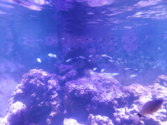
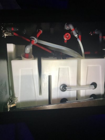
Tim's 800 Gallon Phoenix Reef

count krunk

Valuable Member
View Badges
Joined
Jul 17, 2017
Messages
2,316
Reaction score
4,243
Location
ATL, GA
Rating - 0%
0   0   0
The moon light you have created is amazing! It's definitely on my reef bucket list.

Bummer, all the anthias passed? You will probably hate starting it but once you simply the return plumbing you can sleep easier.

What do you mean by a modified bean animal?
 
OP
OP
garbled

garbled

Well-Known Member
View Badges
Joined
Nov 10, 2018
Messages
772
Reaction score
1,045
Rating - 0%
0   0   0
Well, I have 1 1.5" and 2 0.75", so I can't perfectly do the normal bean animal where the pipes are all the same size. My thought is a 0.75 for the open drain, the 1.5" for the durso, and then the last 0.75 for the emergency.. however.. I might swap around the open and durso.. not sure there.. it's a tough call.

Was also staring at "Seamless Sumps" this week, and was playing around on paper to see if they would work for my sump, and also, if putting them in would make it impossible to work on the sumps. My fear is that if the sump is big enough, I simply won't be able to reach into them anymore because of the awkward placement. Need to do some thinking and planning around that.. With the seamless though, I could use huge 2-3" pipe between them and divide them across the dividers into one giant sump.


count krunk

Valuable Member
View Badges
Joined
Jul 17, 2017
Messages
2,316
Reaction score
4,243
Location
ATL, GA
Rating - 0%
0   0   0
Hmm I would do the largest for the open drain with gate valve, the 3/4 as secondary and emergency.

Those sumps look nicer priced. Site isn't moving friendly so it was hard to get much detail. They come baffled in a set way or you can adjust that to your liking?
 
OP
OP
garbled

garbled

Well-Known Member
View Badges
Joined
Nov 10, 2018
Messages
772
Reaction score
1,045
Rating - 0%
0   0   0
They basically don't come baffled, instead, you can buy them undrilled, and then take a hole saw to them and put the bulkheads where you want them, and the size you want them. That's really tempting, because then I could do multiple ones of various sizes, and connect them all with different sized piping at different heights to get a really large sump with multiple sections out of it.

Just the ability to cross-connect the two sides with 2" pipe is a huge thing for me. I could solve a ton of problems like that, and easily put in gate valves to allow shutdown of one side vs the other. The refugium sump is pretty big too, and with the included glass top I could put a cheaper LED right up against it and not have to worry about salt.

The site is kinda badly made, but they have some decent drawings with dimensions and stuff that I've been using to paper plan. It's a longer term thought, but it might be a feasible solution to my problems. Also, just one of them might be a nice cheap ATO reservoir (I need a BIG res., currently using a glass 20gal tank.)
 

count krunk

Valuable Member
View Badges
Joined
Jul 17, 2017
Messages
2,316
Reaction score
4,243
Location
ATL, GA
Rating - 0%
0   0   0
I think that would work out great for you then. Perhaps a Q1 goal for 2021 ;)

Does one 2" pipe connecting them do the business or would two work better?

And you have one 1.5" and two .75" pipes in both corners correct? Moving to a modified bean animal with returns (perhaps 1" now) over the back would be best case for you I think. With pvc vs the flexible black stuff you have now. I have also found that having your drain pipes coming into a bulkhead set info the top of the sump looks way cleaner and provides some more support for your drain lines.

On my setup I have a .5" thick piece of acrylic that is maybe 4" wide on one end of my sump. I have 3 1" bulkheads in it for the drains, very clean look.
 

count krunk

Valuable Member
View Badges
Joined
Jul 17, 2017
Messages
2,316
Reaction score
4,243
Location
ATL, GA
Rating - 0%
0   0   0
Meme Reaction GIF by Silicon Valley


Waiting for the next update
 
OP
OP
garbled

garbled

Well-Known Member
View Badges
Joined
Nov 10, 2018
Messages
772
Reaction score
1,045
Rating - 0%
0   0   0
Day 20, Never Again

During the period over the last year when I had considerably less time to monitor the aquarium, the RO got out of hand, and caused a problem.

Basically, I have nitrates in my tap water. High nitrates. I rely on the RO to filter all the garbage out of the water, and then the DI to filter the nitrates out. Somewhere along the line, my RO membrane failed. My RO runs on a timer, and feeds into an ATO reservoir, where my ATO then feeds it to the tank. Because it runs on a timer, I don't stand in front of the unit while it's operating, and therefore the little TDS meter on the unit is basically useless, because I'd have to be standing there at 3AM when it refills to check the numbers. Same with the pressure gauge, it's always at 0 when I'm awake. None of this is useful in catching this problem.

This caused the tank to get overrun with cyano. I was at a total loss, as I've previously mentioned as to what was happening, and didn't figure out for a long time that the RO had gone nuts. Having fixed the RO, sure, now it's clearing up. But this shouldn't happen. We have the technology. I own a soldering iron. I am crazy.

20210103_090629


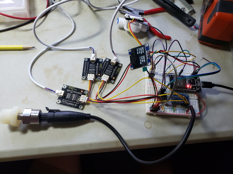
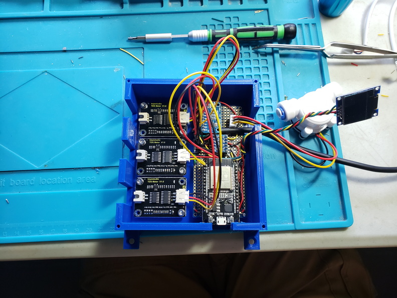
That my friends, is an ESP32, hooked up to a bunch of TDS sensors, a flow sensor, and a pressure sensor. This was my prototype. It took around 3 days to develop, and integrates with Home Assistant. This lets me track and graph TDS, pressure, and flow over time. I can also store a historical record of all these numbers, and go back and look at them whenever I want. I can also set alarms to email me when the values are out of whack. So I needed to move this off a proto-board, and onto a real circuit...

20210103_160903


Printed a nice little box for it too. The TDS sensors are about $14 each off Amazon. The flow sensor was about $10, and the pressure sensor was $20. Total cost to build this was around $90. I even made a schematic for it:

1609784119539.png


I spend about 6-7 hours dipping the TDS probes in different cups of water to test the TDS, and lots of mucking about with a pressure gauge to check the pressure sensor, and about an hour playing with various containers to calibrate the flow sensor. After all that, it totally works. I want to build 2 more for the other 2 RO units in my house, but it was a total pain to solder this, so I generated a PCB and ordered myself 10 from JLCPCB. Should arrive in 2 weeks, I'm pretty excited to see if my first PCB design actually works!

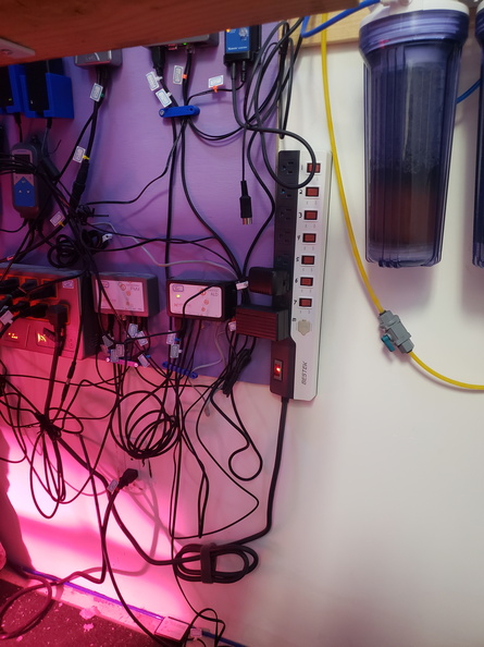
But now the thing to do is to hook it up to the big aquarium. First, I don't have any free outlets on that side, so I needed to move some permanently-on things to a power strip.

20210104_090250


As a bonus, this power strip has a built-in USB power jack, so I can plug the ESP directly into that and not even have to waste an outlet. I moved my Clarisea and my ATO power warts over to the strip, and then plugged the strip into the Apex, just so I have power usage for it.

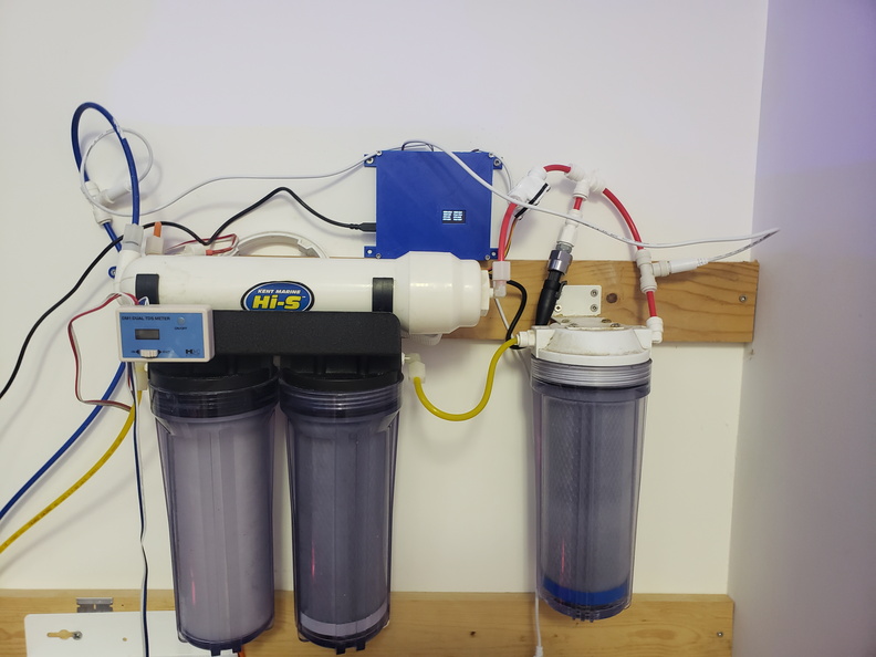
Then I just needed to mount my pretty little box to the wall..

20210104_093816

And a close-up of the display:
1609784119607.png


Oooh, pretty.. The flow sensor is attached to the feed side, so I'm also measuring total gallons that have pumped through the filters. Now I can know how many gallons I'm running through each filter, to better help me know when to replace it. The pressure sensor tells me when the prefilter is starting to give out, and the TDS meters do their job just fine. Only problem is that these sensors are not temperature compensated, like the ones on the manual unit, so I had to measure the temperature of my tap water, and throw it into the code for temperature compensation. It seems to work fine though, the values I'm getting are consistent with the manual unit. The pressure sensor is really accurate at higher pressure, above 20psi. The zero-pressure however, is kinda flaky. Between 0 and 5 psi, it just kinda randomly fluctuates, so it's really only good for monitoring the high pressure during production, but that is all I need it for, so, it works great.

For the code, I'm using ESPHome to program it, which makes the code super simple, and directly integrates with home assistant. The code for this unit is up on my github page.
So what does this give me?

1609784119685.png

1609784119737.png


A pretty display with lots and lots of graphs so I can always know the state of this critical component of my aquarium, and never be caught off-guard again when it starts to fail.

The graphs above show production over the course of about 30 minutes. I emptied out about a gallon from my ATO res, and set the timer to run for 30 minutes. I'll need to write some alarms for this, for now I just have it gathering data. I'd like to have a few days of data before I write any email alarms for it, just so I understand the values coming out of it.

I'm excited to see how the PCB's turn out. Hopefully with those I can slap 2 more units together quickly and have the rest of my water monitored!

I have another huge project underway in the tank, but that one has hit a few small snags, and is taking much much longer than I had wanted, so for now, I lay my head to sleep, and dream of pretty graphs of TDS....
 

count krunk

Valuable Member
View Badges
Joined
Jul 17, 2017
Messages
2,316
Reaction score
4,243
Location
ATL, GA
Rating - 0%
0   0   0
Very very cool! I'm going to steal some of these ideas someday when I have a larger system.

How many stages is your rodi? In that picture it looks wimpy wimpy wimpy!

If it works it works though!
 
Last edited:
OP
OP
garbled

garbled

Well-Known Member
View Badges
Joined
Nov 10, 2018
Messages
772
Reaction score
1,045
Rating - 0%
0   0   0
Day 21, Da flow boss, da flow!

Perhaps a design flaw of this particular aquarium, more due to it's age than anything else, is the return flow. The returns are 1.5" monsters that can dump water into the sumps faster than they can handle them, but the flow back up, is an anemic 2 3/4" lines per side. This was less of a problem when I ran a pair of Dolphin AmpMaster 3000's, as they had insane head pressure, and would just blast the water through. The COR20's are not as impressive:
1610909697869.png
1610909697928.png

Both pumps here are running at 100%. It's pretty anemic IMHO.
Lets look at the plumbing to learn why:

1610910083982.png


1610910128642.png


So, the COR20 feeds to a 1" pondflex, into 1" PVC, to a 1" reducing tee, and then on into a 1" street elbow reduced to 3/4". Inside the overflow, it follows up through 3/4" flexible tubing, and then out through the side of the overflow into the display. On a lark, I decided to calculate the head loss from this, and it came out to around 4000-5000 ft. Insane.
So I needed to set some goals for this plumbing upgrade.
  1. More flow, less head pressure.
  2. Designed for a future sump, and retrofitted to the current one.
  3. Less intrusion into my working area. It's obnoxious trying to get around those cross pipes when working on the skimmer.
  4. Delete the use of the internal flexible tubing to free those two outputs up for a bean animal overflow.
So it occurred to me, that I could just run up the side of the aquarium, and then over the top of the overflow, and bypass the internal tubing entirely. This launched an idea in my head, so I bought some PVC bits..

1610910167190.png


And made this:

1610910213618.png


This is, a 1.25" barb fitting, to Cepex valve, to 2" tee, to FS-200. All built with monstrous 2" pipe, to reduce all restrictions from the additional elbows I'll be putting in. A note on the FS-200 though. Screw Neptune and their insane BSPP threads. I don't know how anyone in Britain has plumbing that doesn't just spew water onto the floor constantly. I tried 2-3 wraps with teflon tape, leaked. A bunch of pipe sealing goop, leaked worse. More pipe sealing goop, no go. Finally, I ended up having to do 10-12 wraps of teflon before the stupid thing stopped leaking. NPT pipe works great with 2-3 wraps. BSPP is a nightmare. Hate BSPP. Stupid BSPP. Booo. Also, cleaning pipe sealing goop out of threads so you can use tape instead is a torture that should be reserved for the deepest pit of hell.

And this:

1610910253041.png


A 2" to 1.5" adapter, to check valve, to gate valve, to 1.5" -> dual 3/4" barb fitting adapter. I went with the 1.5" tubing here, primarily because the cool adapter at the end was only available in 1.5". It made the gate and check valves alot cheaper too..

And now installed:

1610910292356.png

1610910319740.png

1610910366403.png


Now this achieves all of my goals. The routing of the pipe is up and out of the way, so it's no longer causing me problems when I try to work on the sumps or the skimmer. I run it into the central chamber, because in an ideal sump configuration, my return pumps would be there instead. It frees up the 3/4" tubes for an eventual bean animal overflow, and it's got much much more flow. Head loss now calculates out to around 300ft. How much more flow you ask?

1610909697987.png
1610909698047.png


That much more flow. With the pumps running at 60%, not 100%. That net me about 200-250GPH. So why don't I just crank them up to 100%? Well.. math ruins everything.

When the pumps are on, essentially, you are moving part of the water from down in the sump, to up in the display. You basically float a certain quantity up there, by raising the water level in the display over the weirs, so that it can move through them and then back down. How much water? Well, if we raise the display by 1 inch, that's 10' x 4' x 1", or 25 gallons. When I turned on the right side after setting it up, I immediately had to add 3 gallons to the display just to keep the sumps from running dry. Now sure, I could keep cranking up the power and adding water, but eventually, I will add so much, that if I shut the pumps off, the sumps will overflow.

This means, to really get the most out of my new plumbing, I will need new sumps. Which is basically now next on my major todo list, probably in late March to April.

While I was at it with the flow, I needed to correct an issue. Originally, I wired my Tunze Safety Connector into the 6255 on the left side. I tested the snot out of it, and everything seemed to work. 3 weeks ago, I had an actual power outage. Guess what? It didn't work. Turns out, that even with my various tests, when the Apex itself loses power, the Tunze sets itself to zero output. This wasn't the same as just unplugging it from the VDM, or pulling the outlet, the connection did something different.

I was using the 6255 to provide part of the side to side gyre flow, so I couldn't just disconnect it from the Apex, or I would lose that. Luckily, I always need more flow anyhow, so I grabbed a second Tunze Stream 3. I installed this one on the left side, with the flow diverter, in a vertical orientation. I set it to 10 second pulse mode, between 70 and 100%. I really wish they had a longer pulse, but, oh well. This stream is now connected to the safety connector, and when the power goes out, it will provide flow along the top, and hopefully break up the surface to keep everyone alive. It also brings me up to about 16k GPH in the display, which is getting there.. but still not enough. I'll probably throw another WAV on the right side to get into the 20k territory.

With that done, I had one more project to tackle. Another one of the MeanWell drivers for the main LED's was starting to glitch. This is the second one in a month, so that tells me they are nearing the end of their service life. Rather than just keep replacing them one at a time, I decided to swap all 4. This also let me correct yet another historical mistake. Way way back when I built this light, I didn't fully understand the ratings on the COB lights. The seller on ebay listed the light as having a maximum rating of 248W. Obviously I didn't want to max it out, so I got 185w drivers. This was way too much. If I ran them at full, I would burn the COB's out. Now that I'm older and less stupid, I purchased a set of HLG-100-36B's, and now I no longer have to run the VDM ports at 48% to keep from blowing the lights out. 48% wasn't quite perfect anyhow, so I actually gained a few watts of power out of the deal.

And once again, Emperor Angel bless the Anderson Powerpole connectors I used when installing these years ago. I was able to swap the new drivers in with virtually no effort at all.

And as a final capstone, I decided to throw some more fish in the display. I got 4 firefish, and 3 Dispar Anthias (no, I will NOT give up on that dream!). I tossed them in, and everything seemed ok for a bit, and then it went a bit sideways. The male anthias bolted under a rock never to be seen again, and the 2 females went and hid by the cleaning magnet. The 4 firefish though, they seemed fine. My purple firefish however, seemed a little off. He has been the calmest, most peaceful fish I own. When they went it, it set him off. He chased them around a little, and when I left the room for a second, they were nowhere to be seen. This was on Sunday.

After a few days, I basically wrote them off. Doomed from my mistake. The purple firefish was still a bit uppity though, and his swimming range had expanded by at least 2-3x what it was before. And then on Thursday, while feeding, one of the newbies popped up from behind a rock. I peered through a hole in the rockwork, and could see 1-2 more down in there. There is a ton of open space behind my rocks, so plenty of space for fish to hide. This also kind of explains why the purple one has been moving about more, I think he knows they are there, and is keeping watch. I haven't seen them in the last few days, but he is still acting uppity, so maybe that means they are still there? More dither to fix?

I'm kinda hoping this problem is self healing, or that I learn something from it other than "I suck at fish"...

As a final note, the Cyano is about 60% gone now. Just fixing the RO/DI was all it needed. Its dying back at an incredible rate.. The rocks below were 100% covered just a few weeks ago..

1610910435702.png


And now, with more flow, and slightly better lighting, I lay my head upon the pillow, dreaming of sump designs that anger me less...
 
Last edited:

count krunk

Valuable Member
View Badges
Joined
Jul 17, 2017
Messages
2,316
Reaction score
4,243
Location
ATL, GA
Rating - 0%
0   0   0
Do you have a link or care to explain your diy lights some more? Some pictures of the whole unit?

You have a 95w driver now, you run the lights at what wattage? You have a nice heatsink that enables fanless cooling, how many LEDs per puck and how are they wired up?
 
OP
OP
garbled

garbled

Well-Known Member
View Badges
Joined
Nov 10, 2018
Messages
772
Reaction score
1,045
Rating - 0%
0   0   0

I wrote up an article on how to do it. They are 100w COB LEDs. 1 per driver. They are pretty powerful, have good spread. The only issue is the solar tubes get in the way of an ideal mounting spot, so during the winter, my light input is less than I would love to have. (due to the design of my house, and where the sun hits it).

That's why I'm thinking of throwing 3 Kessils on, because I can nestle them right up next to, or inside the tubes, and cover a few dark spots with them.

As for fish.. yeah.. I will. It's finally getting there. I'm up to 30, still in the peaceful phase. I want some more dartfish, probably blue gudgeons or scissortails, a dozen or so would be nice. But yeah, I really do need somewhere in the 60-100 range, especially if I'm not throwing monsters in. I could do a few more random anthias, maybe some chromis, but eventually I need to do the big fish like the tangs.
 
OP
OP
garbled

garbled

Well-Known Member
View Badges
Joined
Nov 10, 2018
Messages
772
Reaction score
1,045
Rating - 0%
0   0   0
No huge updates here. Just did water testing today. Cyano is about 90% gone. Nitrates 0.0, Phosphates 0.0. I'm feeding pretty heavily, so I've disabled the vinegar again. Looks like all the nitrates from the failed RO have been cleared out. Cyano is clear enough I can start throwing some test frags in again, and see how it does... Hopefully..
 

count krunk

Valuable Member
View Badges
Joined
Jul 17, 2017
Messages
2,316
Reaction score
4,243
Location
ATL, GA
Rating - 0%
0   0   0
I don't remember if you mentioned this or not, but are you running a CaRx? Or have plans to? I imagine water changes aren't done all that often due to size, so I'm curious what you are dosing. I know you have probably covered it, but I don't remember haha.
 
OP
OP
garbled

garbled

Well-Known Member
View Badges
Joined
Nov 10, 2018
Messages
772
Reaction score
1,045
Rating - 0%
0   0   0
I'm running kalk right now, with a CaRx waiting in the wings. Basically once the kalk can't keep up due to the topoff limitation, then I'll turn the CaRx on, and run both.
 
OP
OP
garbled

garbled

Well-Known Member
View Badges
Joined
Nov 10, 2018
Messages
772
Reaction score
1,045
Rating - 0%
0   0   0
Just an amusing followup today. On 1/9 I added 4 firefish to the tank. They all immediately hid. A few weeks ago, one came out, and I assumed the worst..

Last night, all 4 were swimming around. They hid in the rocks and still found food for an entire month.
 
OP
OP
garbled

garbled

Well-Known Member
View Badges
Joined
Nov 10, 2018
Messages
772
Reaction score
1,045
Rating - 0%
0   0   0
Day 22: Starting the final push

I've decided to tackle everything left that annoys me about this tank at once. Sumps, light issues, wire routing issues, overflows, everything. Here we go.

First, added a few new tiny fish:
1615897605898.png


The dartfish survived really well, despite how tiny they were on addition. The chromis didn't fare so well, but I kinda expected losses there. I have about 6 left of the chromis, and a grand total of about 10 dartfish, including the two I already had. Also added a small midas blenny:
1615897710863.png


But on to the construction!

1615897781132.png


Some items arrived.. I won't go into everything just yet, I'll cross the roads as I get to them.

First order of business was to replace the two TLF media reactors. I really liked them, however, it was difficult to exchange the media in them, and that made me lazy about doing so. The BRS reactors seemed easier to swap the media in, so I decided to give those a go. It was easy enough to swap the plumbing around, and I actually think the mounting ended up nicer, and cleaner looking in the end, so, overall, I'm happy with this.

1615897970913.png


Next on the list was I needed another EB832. I was running short on power on the right side of the tank, and I wanted to add a bunch of things over there. Along with the EB832, I added another VDM, another FMM, and a PM1. The PM1 will eventually be for my calcium reactor, but for now, I just have it wired to that blue 3D printed box.

The 3D printed box is an experiment I've been working on for awhile. I call it the Ultimate breakout box. It has two breakouts on terminal connectors, then a humidity sensor, and then two colorimiter sensors that I'm experimenting with to be able to alert me when the DI resin needs replacement. It's not 100% working yet, so once I get a bit further, I'll post something about it in the DIY forum. Right now I'm still trying to figure out the data..

Also seen in this photo is one of the drivers for the Orphek OR2 bars, and a Kessil A360 brick. The other 2 kessil bricks will sit next to it.


1615898037088.png


Next on the list, I want more flow. I just plain don't have enough in there. I calculate the average flow around 12,000Gph (that accounts for the fact that at any one time the pumps are on a schedule of ramping up and down from right to left, so they are never all at full blast). I decided to slightly move the existing WAV pumps, and then add a second one to each side of the tank.

1615898460205.png


1615898634700.png


This brings me to an average of about 16-17k. Max of about 28k. Getting there. I could see adding one more maybe, but running out of places to put them. That puts me at:

2 Tunze Streams
1 Tunze 6255
4 WAV

Not too bad.. I think.... maybe?

So now I have a bit more flow in the upper tank, and it's time to switch my attention to the first of the three big projects. One of the largest problems I have, is I have no reasonable way to perform a water change on this tank. With it being in it's own room, connected to the garage, I can't wheel a Brute can in there, because there is a small step in the garage. Even if I overcame that, then I could never get the can back out, and there is nowhere to dump the saltwater. I guess I could do the street, but... ehh..

Basically, as part of a bad design of the room itself, I just cannot easily move water in and out, or make up saltwater. If there was ever an emergency and I needed SW, I'm just hosed. In theory I could take the frame down in the front, and run pipes over the front, but that's a pain, and takes two people to do.

So the "simple" plan is to get 2 65G Norwesco water containers, one for salt, one for RODI. So obviously I figured I could just order some online. They are about $200 each, how much could shipping possibly be? Well, the answer to that is, $350, each. Just shipping. So it would have been $700 to ship $400 in stuff. Absolutely insane.

After a bit of digging, I found that Tractor Supply had 2 in stock in Arizona. The problem was, it was only at their Mesa store, which was 55 miles away. My tiny car is not ideal for transporting giant water tanks, but I wasn't going to be defeated. I placed the order for pickup, emptied my car out, and prayed alot. I drove 55 miles out, loaded the first one in, and like I thought, there was no way on this planet the second one would fit in the car. So I had to drive all the way home, drop the first tank off, and then all the way back... Took about 5 hours, 200+ miles, it was a long long day. Still better than spending $700. And before you ask, no I couldn't really use a friend with a truck, the current state of the world didn't really leave me that option open...

So now I have two giant bins, after a very long nap, and a pile of parts to install.

1615900407776.png


First bin:
1615900230745.png


This is the salt bin. It gets a temp probe, an OS-2 optical sensor, a boring float switch, a float valve, heater and mixing pump. I drilled a few holes for the various probes, and a hole for all the cords to run in and out so I could still use the cap to seal it all up. The optical sensor gives me the low water mark, and the float switch tells me when it's full.

1615900648363.png


I used some rigid tubing for the line that will draw water from the tank. The tubing extends down just below the optical sensor, so when it draws enough water, the sensor will show OPEN, letting me know I need to refill.

Second bin:
1615900458795.png


This is the second bin. It gets the same OS-2 and float switch/valve, and then a PMUPv2. This will be the RODI bin, and will use the PMUP to move the water from it, to the saltmix tank.

1615900562602.png


Here you can see the PMUP sitting at the bottom of the bin, with the optical sensor mounted. It's hard to see the rest from this photo, but the float valve and switch are also mounted up at the top.

One of these bins will be in the tank room, the salt bin, as that needs to be temperature controlled. The second bin just won't fit there, so it goes into the adjacent garage. The water will get hot/cold there, but there isn't much I can do really. It's the best possible scenario.

Next thing to do, was to mount the DOS's and the pile of solenoid valves:
1615900858851.png


The water comes out of the RO/DI, and into the first valve. This is the master valve, and is just kind of a quick way for me to stop all production. From there it goes into a Y fitting, into a valve for the ATO Res, and then the big RODI bin in the garage. Cables are routed down, and then through the wall into the garage.

I found a handy little wall shelf, that holds the DDR nicely, so that is mounted up on the wall above the barely visible salt bin.

I haven't plumbed up the DOS's yet, because I have another project blocking that.. more on that later.. But for now, here is that corner, mostly completed:
1615901090630.png


I ended up putting a 90 elbow on the water coming out of the wall, because I don't want to ever bump the bin, and damage the fitting with high pressure water coming out of the wall. This makes me feel a little safer with this giant complex setup. Also, because previously, I was using a watering timer to fill the ATO Res, I never had one of those ASO valves on the RODI to shut it off when it wasn't producing. I realized after a day or so that it was just spewing wastewater into the yard 24/7. So I had to install one of those. I find it interesting how they work. Once installed, it did not stop the flow. Instead, the flow has to be running, and then suddenly stopped. Luckily, the master solenoid covers this well. I think I'll add a flow sensor to the waste line, and add some programing to check if it's running when the master valve is off, and either alert me, or maybe cycle the valves on and off to try and stop it. We will see.

One more note on the bins. The remote RODI bin was far enough away, that the wire from the optical sensor wouldn't make the run. It turns out, you need a 4 conductor wire for the extension, a normal stereo cable will NOT work. Search on amazon for a TRRS 3.5mm cable. Once I found one of those, the remote bin was working properly. I got the shortest one that would make the run, which was about 4 ft.

Speaking of programming, my Fusion dashboard is getting a little complex. I won't go fully into the programming, as it isn't working 100% yet, but it's getting close..
1615901677985.png
1615901709891.png


The SV's are the solenoids. The LO/HI are the various float/optical sensors. The ACT are "activities", which are virtual outlets that determine when an activity is running. Finally, the READY are virtual outlets that say when the various stages are ready for the next.

In short, when the RO bin is empty, the ACTFILLROTNK flips to on. This says to turn on the various valves, to fill the tank. It doesn't start until it's completely empty, and only turns off when completely full. This takes around 16 hours. When the RO bin is full, it flips on RO_BIN_READY.

If the RO bin is ready, and the salt bin is empty, then ACTFILLSALT kicks on. This turns on the PMUP in the RO bin, and moves the water into the salt bin until it's full. Once the salt bin has water, it starts turning on the heat and mixing pump. Once it's finally full, then the manual step comes in. I have to add salt. Eventually I plan to measure out exactly how much salt is needed, so I can pre-measure it, and just be able to dump it in, but this will take awhile. Once the salt is in the bin, I flip the SALT_ADDED over to ON manually. This starts a 900 minute timer. When the timer is done, the SALT_READY flips to on. This will eventually tell the DOS it can do automatic water changes.

I still have a bit more work to do here.. but it's getting closer to being functional in this area. But on to something else. (wow, this post is just jumping all over the place, but the reality is, I'm doing like 7 projects at once in there, so...)

1615902259239.png


Now I have all three Kessils wired in. The board is getting more full, and the wires are a hot mess. I have a long term plan to clean this up, but want to wait until all the wiring is in before tackling it. I'm also being SUPER vigilant this time about labelling every single cable. It's so much nicer when every connection is labelled and I can easily find where things go, or if I have to disconnect something in an emergency, know where it's supposed to plug back in. For example, on the DOS, the DOS end of the cable is labelled EB832-TR and on the EB side, it's labelled DOS_AWC, so I know which thing each side goes to.

1615902459865.png


I added 3 new Kessil A360's to the tank. These are mounted pretty low, to give a good spread. I used some 1/8" angle iron, and mounted it to the wall, to give me a rim to mount the brackets to. This also lets me slide them around a bit if needed. For anyone wondering, the gooseneck arms on a kessil, are NOT strong enough to hold it up, if you mount them at a 90' angle to the wall, and just jut them straight out over the tank. They just fall down. You need that arc for them to work. I needed some extension wires to attach the kessils, so I picked up some extension 3.5mm stereo cables from amazon, and for the power, you need a 5.5mm x 2.5mm (NOT 2.1, which is what most of them are) DC extension cable. I made little holes in the wall brackets, so I could ziptie the cables to them, to try and keep things neat. I may end up adding two more lights in here, big DIY ones like the 100w units I have above. Waiting to do a full PAR test to see if I need to or not..

Overall, it's been a hectic few weeks. I'm still sorting through a million parts, and adding them a little at a time, working pretty much every night on the tank. The next big part of the plan is something I've thought about since day one, and this will be the big one. It will probably take me a few more weeks to finish.. but a quick teaser image..

1615903046265.png


The living room is a hot mess of boxes. My wife is going to kill me. But slowly, I'm whiddling away at it. Normally at this time, I would lie my head down and sleep, but I still have so much to do.. no rest for the weary. I must press on..
 

Attachments

  • 1615897420179.png
    1615897420179.png
    1.6 MB · Views: 58
OP
OP
garbled

garbled

Well-Known Member
View Badges
Joined
Nov 10, 2018
Messages
772
Reaction score
1,045
Rating - 0%
0   0   0
Day 23 - Continuing the final push...

In the beginning, there was a sump. It consisted of 6 30g rubbermaid tubs that were not rated to hold water, and caused all kinds of problems. (but man did they grow algae!)

After the great disaster (see page 1), the sumps had to go, mostly because they were going to break one of these days, and make everything horrible-er. The problem was, I had no idea what to replace them with. The resurrection of the tank was performed, by just giving up on having a proper sump setup, and going with anything to make progress. So I threw 2 trigger Ruby's down there, and called it good.

It was not good.

Essentially, there was a right side, and a left side. There was a small tube connecting the two, but it did not do a good job of evening the water levels across the sumps. If one of the pumps shut down, or one of the drains stopped for any reason, the other side would have problems, and the whole thing was a hot mess. I had like 20 lines of Apex code to detect these problems and fiddle the pump outputs around in the event of this, and it did work, but I was constantly fighting the left side running the pump dry because one of the weirs had a little more algae in it, etc etc etc. I knew full well when designing this, that it wasn't ideal, but it was just causing me infinite ongoing pain, and had to be corrected, I just had no idea what to do.

Now I know what to do.
1616769975436.png


What you see here, is a 3d printed model of the underside of the tank. 1" == 2mm. The little boxes are Seamless Sumps. Each one is about 17-20g, and they are made of the same polyethelyne as water storage tanks are. I printed this model, and then a whole bunch of the little sumps, so I could try out different combinations and arrangements, and then settle on a final purchase. Because I learned years ago that the 3 sections are not all the same size, you can see that I have less sumps in the right section. It took me a few weeks of fiddling with this model before I finalized a design I liked, and then I ordered them.

Individually, they aren't that bad. About $170-$200 each. Of course buying 8 of them adds up quick. (I got one extra small one, just in case my model was off a little, more on him later...) Total with tax and shipping was about $1700. They arrived in about a week, all in great condition, and I was super happy with them.

The next thing to do was to plan out the layout with the actual sumps.
1616770441185.png

So here is the layout, on the living room floor, more or less aligned how I wanted it. I ended up moving some stuff around, but this was the general plan. The two in the center are baffle tubs, which have a section for the pumps in the front. I have 4 of the large tubs, and then 1 small tub. The idea is that the drain pipes enter the right and left sumps, snake their way through the maze of sumps, and end up in the center two baffle tubs. Then I would connect the two baffle tubs, and have the return pumps push back up to the display.

Now obviously, this was not without some problems. Actually, it was mostly all problems. SO many problems. Lets start detailing them! Yay!

1616770716301.png


Everything you see in this shot has to go.. Obviously. But the keen eyed of you might notice a pile of sawdust. That's because those uprights were 16" apart. And these sumps are 17" wide. So the uprights had to be moved.. again.. an inch or so out of the way. With the existing sumps down there, it made cutting a total nightmare, and was basically done by hand with a hacksaw over many hours.

1616770860885.png

Then I got to repeat the process here....

1616770905828.png


And here too! The only nice thing about this 6 hours of work, is that now it's actually a little easier to move around down there, and get to things. Before it was so tight it was a nightmare to do any work at all down there. This extra 2-4 inches of space made a world of difference.

1616771059765.png


The next issue is, I needed to be super sure I understood the water dynamics in this setup, before I started drilling holes. Do the holes need to be drilled up high, to keep the water levels high in the refugium, or should they be down at the bottom for extra flow? So I made another model. I grabbed 3 $5 trash cans, and plumbed them up with some leftover bulkheads from the original sumps, and ran some water in different configurations to understand how the water would flow, and where it would overflow. This wasn't a 1:1 model, but it helped wrap my brain around the flow, and made sure I wasn't going to make a $1700 error. (don't worry, I tried really hard to make those errors anyhow!)

1616771289242.png


Now one of the nicer features about the seamless sumps, is that they have little indents on them, so you can drill bulkheads and have them all lined up nicely. I decided to go with 2" bulkheads, because I don't want any flow restrictions or backup at all. My original sumps had 2 1.5" between them, and I found that if I used just 1 of the two, it was a little shy...

So I took one of the small sumps, because I knew I had an extra of that one, and drilled away. Installed the bulkhead, screwed a plug into it, and then leak tested.

Leaks everywhere. Argh.. WHY? Well, it turns out, 2" was just very slightly too big for that bottom position. While it LOOKED ok, the flange of the bulkhead met with the slight curve of the inside bottom, and wouldn't seal properly. I tried multiple gaskets, 3d printed a bulkhead wrench to tighten it, everything. Nothing would make that thing seal. Which means I just broke that mini sump. So what you see in the above photo, is me measuring 5/8" above the indent, and marking there for the center of the drill. This way it wouldn't hit the bottom curve again.

Of course, having just wrecked a sump.. I had to now hem and haw and stare at it for a day or two before I had the guts to drill again, because if I broke this sump, well, now I would have to order another one, and that was bad. Eventually however, I mustered the courage, and set the drill on it, plumbed up the bulkhead, and this time it sealed.

1616771753240.png


So this is a shot after a leak test. Basically I took two threaded bulkheads, installed them backwards (Yes, I know) and then threaded a 2" nipple between them. With generous amounts of PTFE tape. I basically screwed the bulkheads together onto the nipple, and then installed the set onto the pair of sumps, added the nuts, and was good. This was terrifying. All of this was just the prep work. I hadn't touched the actual tank yet. Now it was time to close in on that...

1616771913794.png


6 hours later, I have finally extracted everything from the left side. I had forgotten what an absolute nightmare it was to get that Ruby sump into the location it was, because there was only a 1/2" gap between it and the wall, meaning it was impossible to rotate. Now I had one covered in 2 years of ick that I somehow had to un-rotate to get back out. I also had to undo all the plumbing down there, un-run every cord and wire and piece of equipment. All on my hands and knees, and it hurt, alot. But I had it all out now. I actually had to go back to my own post to see if I had details about how I got it in there in the first place...

1616772198383.png

Moment of truth...

1616772243654.png


And it fits! Barely. This was another 2+ hours of work, because while the rear two went in like butter, that last one was a nightmare. I didn't consider that the opening was in the center, and once the rear one was in place, that the front one wouldn't fit past it to move into position. As it turns out, the distance between the 2x4 on the floor, and the supporting beam under the tank, is exactly 1mm shorter than the height of 2 of the sumps, meaning, I had to force the sump in on top of the other one, and then slide it over. Also meaning I will never ever get that thing out of there again. You can also see at the bottom the little 3d-printed nut wrench I made. Worked great.

Also in the photo, is a tiny metal round thing. That would be a can of Dupont 111 gasket sealant. I was uninterested in leaks, so every gasket got covered in that before the bulkheads were installed.

1616772552887.png
1616772582189.png


And now the middle section was prepped and installed. This photo makes it look easy. What I can say is, it was not. This was at least 8 hours more of pain and suffering.

What I did, was install just the left half of what was shown here, because I wanted the right side of the tank still operational, so the fish wouldn't die. So I installed the left baffle sump into place, and hooked the Cepex valve to it, so I could just shut it off and not have water everywhere. The problem I did not account for was one of the rearmost vertical uprights. It was right on top of where the bulkhead wanted to cross between the baffle sump and the left section.

This was of course, another one of those, did I just make a $1700 mistake moments. I spend another few hours slightly fiddling the positions of the sumps, to get enough space, because there was absolutely no way I was going to move that particular upright, because it was right under one of the 2x8 beams that held the tank up. Not touching that. Nope.

Luckily, with hours of minor adjustments, I was able to fit it all into place, and get things lined up just right, with 1/4" of gap between the cross-pipe and the upright, and made it work. Oh what a nightmare.

So now, with the left side plumbed in, and water moving through it, it was time to tackle the right side.
1616772998105.png
1616773027823.png


This side was a million times easier to put together, however, that elbow between the two took a long time to measure and cut just right, so everything fit together without gaps and bending. What you see here is about 8 more hours of effort.

Also seen here, is the original "you drilled it in the wrong place" sump. Which I was hoping to use as an RO topoff container. (it's quite nice for one honestly, I highly recommend them!) I 3d printed a tiny ring, to space the nut off the back in the hopes it would fix the leak. It didn't. More on that later.

1616773228237.png


I also have a 3rd pump, a COR15, that runs various accessories, like the carbon, and the dump bucket, and the sponge bucket. This needed to be re-plumbed entirely, so I re-used one of my FS-100's from the older return pump plumbing, and ran a pipe across the back for that one. This pump was actually one of the high-pain points of the original setup, as it unbalanced the entire setup of right to left.

1616773462820.png


And now most of the auxilliary stuff is plumbed back in. The 2" drain is just temporarily set (no glue) into the first tub (the left side is basically the same), and the RO setup is wired into the mini tub.

While drilling the final hole in the right baffle tub, I nearly made a fatal error. At the bottom of each of the baffle tubs, there are small raised areas, where you can set media trays on. Because I'm entering the baffle on a different side, it turns out one of these raised areas is right up against the side of the tub, and I completely failed to notice this in my days of planning cuts very carefully. I very nearly drilled through it! That would have rendered that whole sump useless. As it was, it was a huge problem, because now I had a hole in the sump, but I can't put the nut on the bulkhead, because it was right up against the edge. I ended up 3d-printing another fix-ring, this time a C-shaped one, that offset the inside nut about 30mm, so I could avoid that bump. Luckily, this time, it worked. The nut sealed, no leaks. Disaster averted.

Only thing left to do was to fire up the right side, and get it all back online. At this point, I'm 30 hours into the install, and completely exhausted, so I decide to leave it overnight, rather than fight leaks all night...

The next morning, bright and early, I start firing up the right side, and thankfully, that goes without a hitch. Now both the left and right sides are running. It wasn't actually that easy.. but..

So the total volume of these sumps, if completely full to dangerous levels, is about 150g. At reasonable levels, it's about 110-120g. The previous 2 Ruby sumps were, maybe 20-30 each? And I ended up having to discard alot of that water, because it was just chock full of mulm. That meant I needed to add about 100g of water into the system. This is one of the reasons I setup the water change station, I knew I needed all that water just to fill these bad boys. The left side needed 40 gallons just to barely cover the pump, and I could only run it at 25%. I ended up putting 45 gallons in, and then started making more. I had to run both pumps at 15% for a day while the salt mixed up, and I could dump another 60 gallons down there. At which point, I could finally run the pumps up to 100%.

1616774659227.png


The Seamless sumps come with really nice glass covers, which I could use in a few places, not all. The great thing about that rear one, is that it lets me drop the light down super low, and not worry about salt splash on it. I picked up 2 ViparSpectra 600w (not really 600w, more like 150) grow lights, and hung them. Right now that's at the lowest setting, I will be slowly ramping them back up to full. The protein skimmer went into that mini tub in the back, and fits really nicely, and I have a shorter run now to the skimmate locker. It's actually alot easier to get to the skimmer now for maintenance, even though its way in the back.

1616775963013.png


1616775986206.png


The final-ish part of this setup, is running all the tubes for the AWC, and the dosing pumps. I 3d printed some nice brackets, and mounted them everywhere, and then ran all the tubes all over creation. This still isn't done completely, but it's getting there. You can also see the other sump light in this pic.

So.. 30 hours to install the sumps. Another 8 to get them tuned up and working. I've also done maybe 16 hours of work running tubes and cords and cables and trying to organize it all. Mission accomplished?

Oh god no. I have so many problems to solve..

Problem the first. There is a tiny leak between the left side sump block and the left baffle sump. It's like a pinhole leak, and barely coming out. I've mucked with that one for hours, and I don't think I can fix it. I'm kinda just hoping at this point that the salt seals it up. Yeah. I know. Shoulda used more tape.

Problem the second. The clarisea just will not work with this setup. The 1" input is anemic compared to the 2" pipe, and I don't want to just cram it down in there, it will just cause problems. Instead I want to buy a pair of Aquamaxx AF-1's, because they have 1.5" inputs, but MarineDepot is sold out of them.. argh. This is why the drain plumbing isn't glued yet. I want to get the parts and see how they will fit, and then hard plumb.

Problem the third. Remember that mini tub I broke by drilling to low, and then decided I could rescue with a fix-ring, and then re-used as an ATO res? Yeah, here is a surprise. It leaks. Like crazy leaks. I tried more gaskets. More goop on the gaskets. I even just spewed silicone around the outside of the bulkhead, which slowed the leak, and moved it... Once this batch of water in the res empties out, I'll pull it out again, and then apply a bunch of epoxy around the bulkhead, and just pray that that works. I guess if it doesn't I'll buy a new one.

Problem the fourth. The return pump flow is odd. When I took the left side down, I had all the flow into the right Ruby sump, and to keep it from overflowing, I cranked that pump up from 60% to 100%. While it was running, it was pushing the flow at 850GPH according to the FS-200. When the pump was at 60%, it was pushing ~600GPH per the same return plumbing, and FS-200. Now with both pumps running at 100%, they are both showing the same numbers they used to have when they ran at 60%. I don't know if something is off with the pumps, or the flow sensors, or what here. I should be getting 800 out of both.. it feels like I am, looking at the water, but the numbers are nonsense.. I don't understand, but I haven't had time to debug it.

Problem the fifth. The sponge bucket started leaking. I had to rotate it ever so slightly, and while doing so, I pushed on the 3/4" tube coming out of the uniseal. Now that uniseal leaks, and nothing I do will make it stop. I've had to cut that off from the system, and purchased a new uniseal, and I'm hoping replacing it will fix it.

Problem the sixth. The cords for the COR20's are too short. They don't even sell extension cables for them. They do make it, just barely, but I have to run them in a way that displeases me. I don't know if this is solvable. If I can't fix problem 4 though, I could see maybe replacing them with Octo 8's...

So. 30 hours of labor to get the sumps in. About 10 more to tune them and fill with water. I've easily spent another 20 or so doing wires and tubes trying to get the minor things plumbed up. 6 major ongoing problems to solve. Am I happy?

Yes. OMG yes. The setup is so much cleaner than my old one. These sumps are great. I have like 5 times the volume for the refugiums, and the flow through them is way way better. The lighting on them is better too, by a longshot. I don't need as much stupid nonsense equipment and light blockers and grates to keep algae out of the sponges and skimmer problems and on and on and on. The levels of the two sides are consistent. I can just turn one return pump off and nothing bad happens. I can isolate the two halves with the Cepex valve instantly. The ATO setup is 100 times better. Everything sucks less. I just have another 24+ hours of labor to do to fix leaks, problems, and do more wire/cable/etc management, and hookup the AWC.

So I'm basically on the home stretch now. I'm just tuning problems out, finishing up some wiring, cleaning some stuff up. But more or less my sump problems are finally getting solved. I think I might have a forever solution now, so, I'm happy with that. I might do some tweaks here and there, but this is it, it works.

The room is still a mess, and I'm still doing work.. but.. yeah.. I think this time I'll stay up, and keep working...
 

JumboShrimp

5000 Club Member
View Badges
Joined
Aug 12, 2018
Messages
5,806
Reaction score
8,226
Rating - 0%
0   0   0
5724B102-A123-4A67-9F13-043BE45708F7.jpeg

Great write-up about your Seamless Sump journey. I use them inside my 150 gallon stand; either not too many people know about them, or choose for whatever reason not to use them. But I like them. Best wishes!
 

Bubbles, bubbles, and more bubbles: Do you keep bubble-like corals in your reef?

  • I currently have bubble-like corals in my reef.

    Votes: 22 34.9%
  • I don’t currently have bubble-like corals in my reef, but I have in the past.

    Votes: 7 11.1%
  • I don’t currently have bubble-like corals in my reef, but I plan to in the future.

    Votes: 21 33.3%
  • I don’t currently have bubble-like corals in my reef and have no plans to in the future.

    Votes: 11 17.5%
  • Other.

    Votes: 2 3.2%
Back
Top