OP
OP
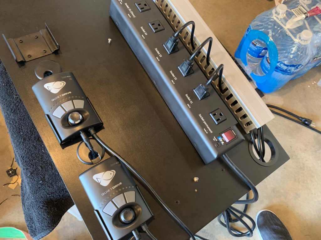
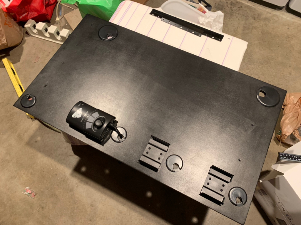
this is a great build thread. Keep up the documentation. I think I am going to use your same idea with the projector mount on my build.
Thank you!
Awesome! Glad someone else likes the idea and can use it.
Follow along with the video below to see how to install our site as a web app on your home screen.
Note: This feature may not be available in some browsers.

this is a great build thread. Keep up the documentation. I think I am going to use your same idea with the projector mount on my build.
Thank you!


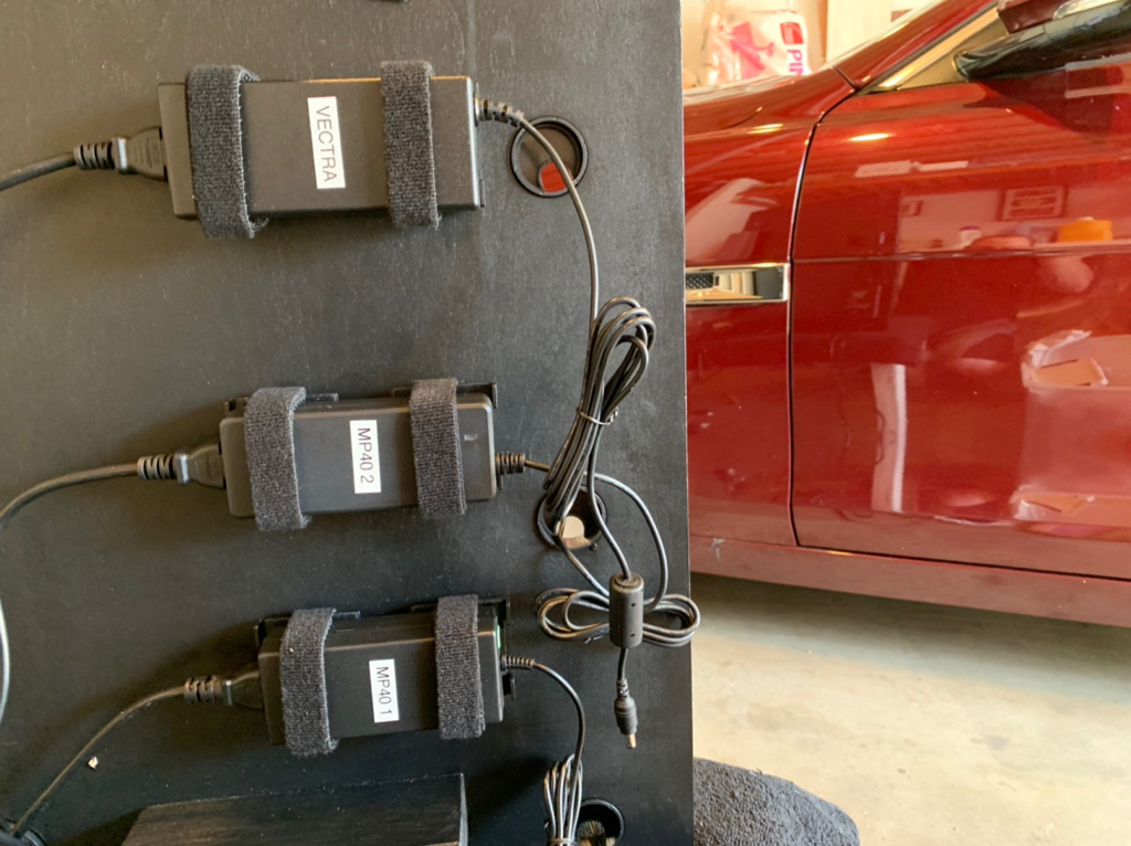
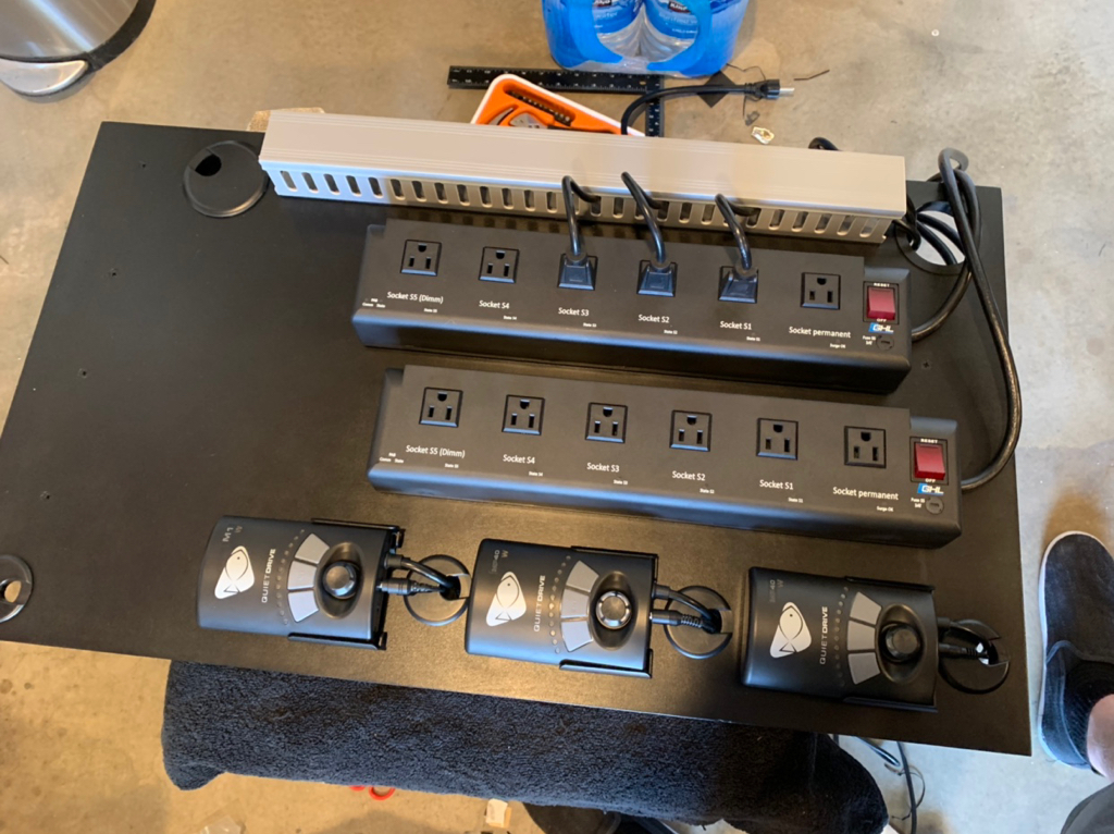
Sweet! Super clean!


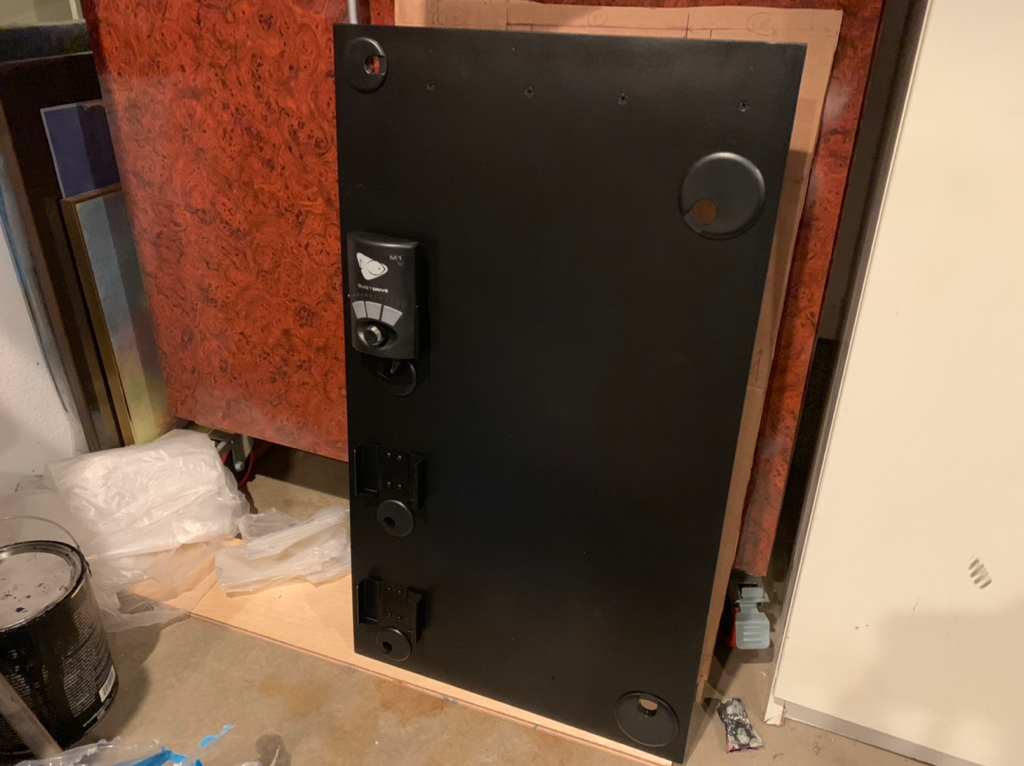

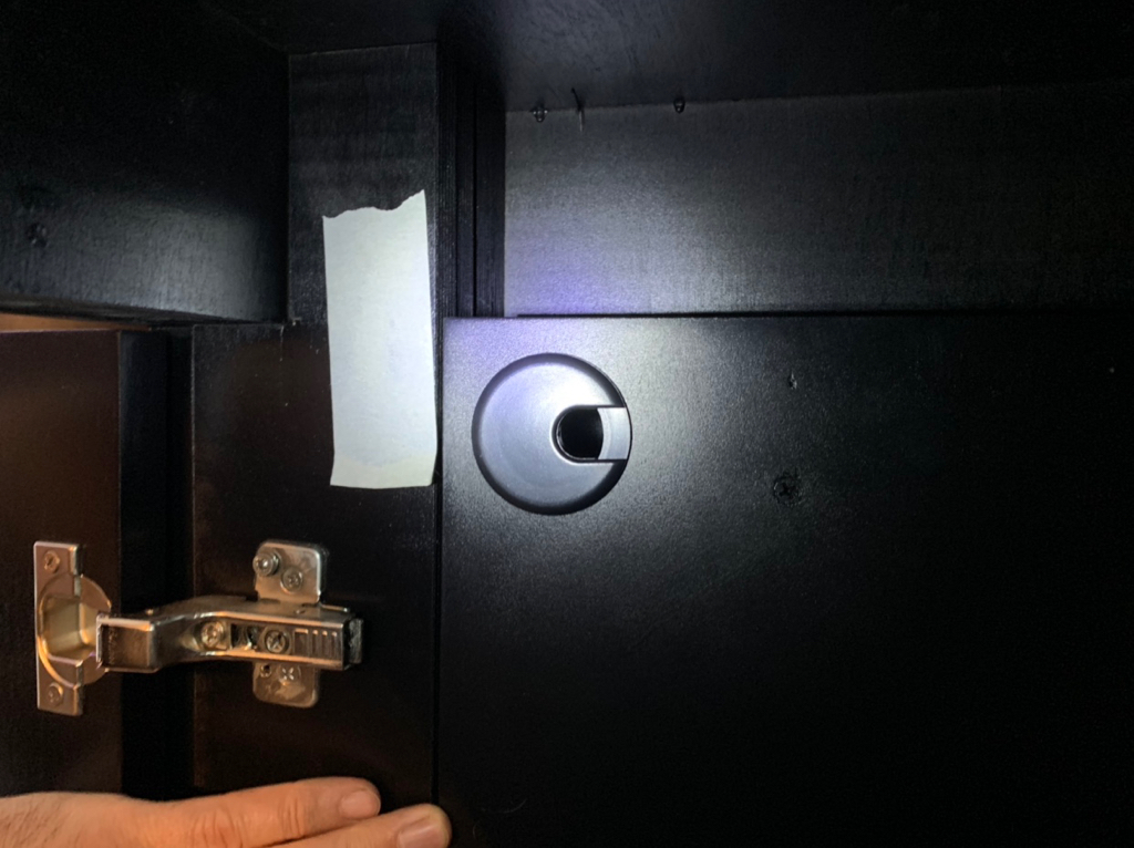
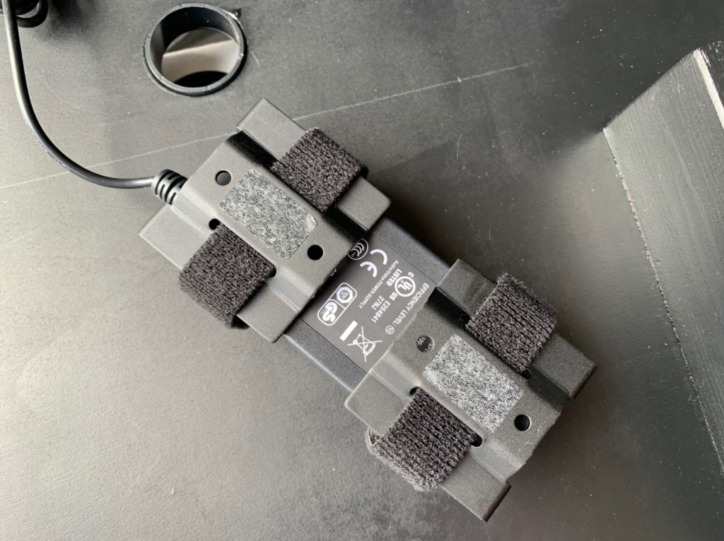
The devil is in the details!
Keep the updates coming!
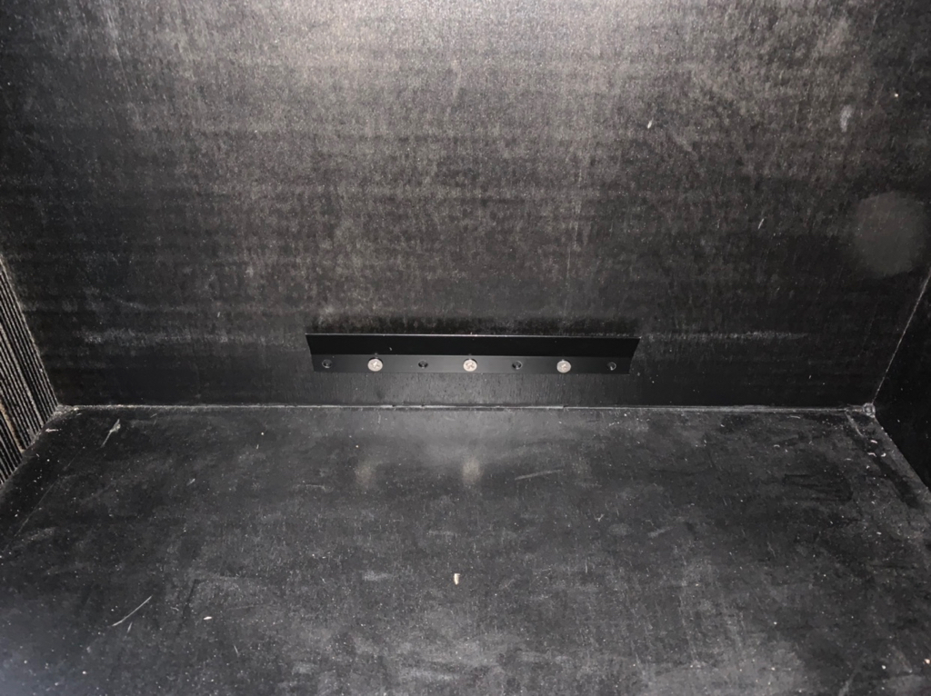

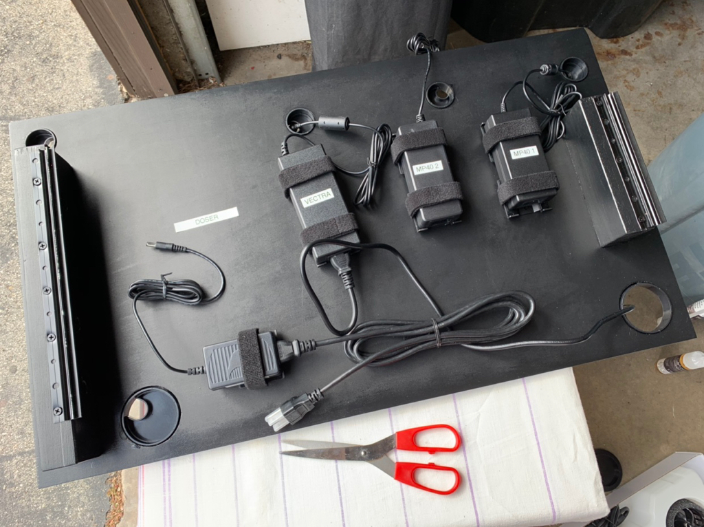
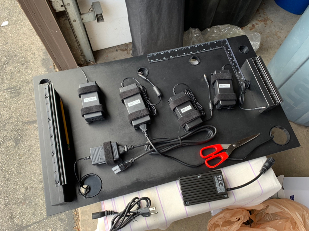
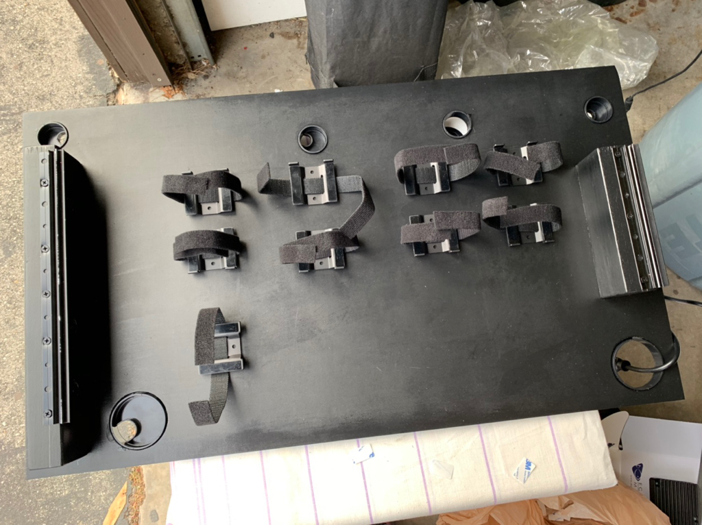
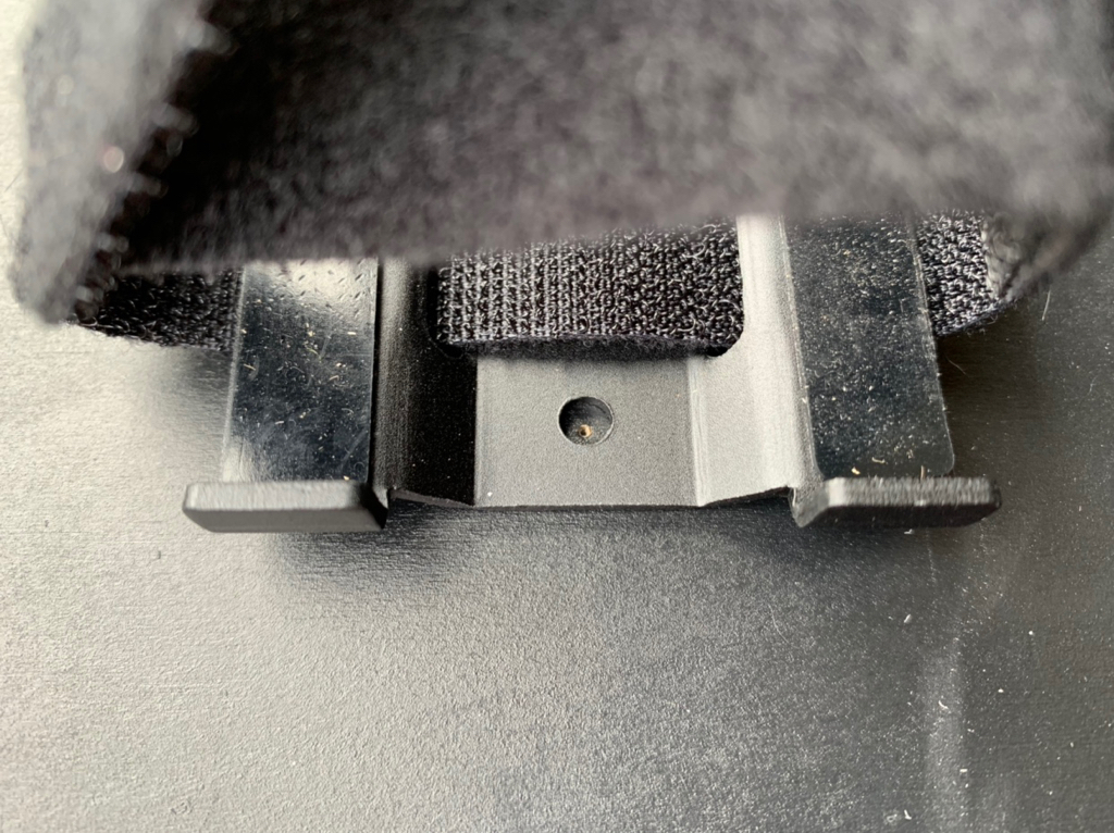
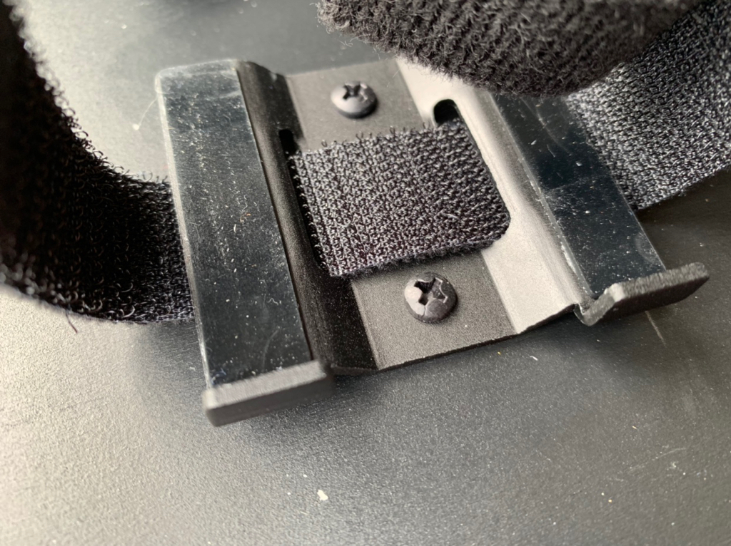
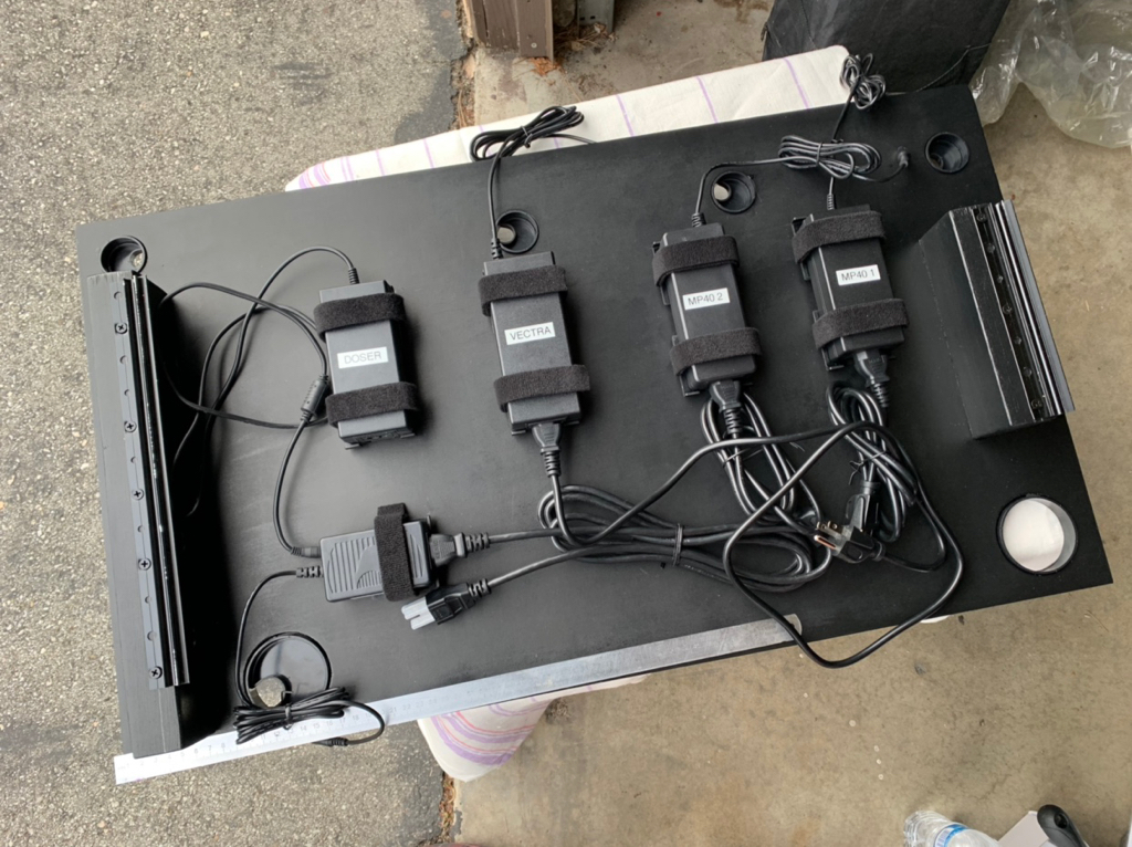
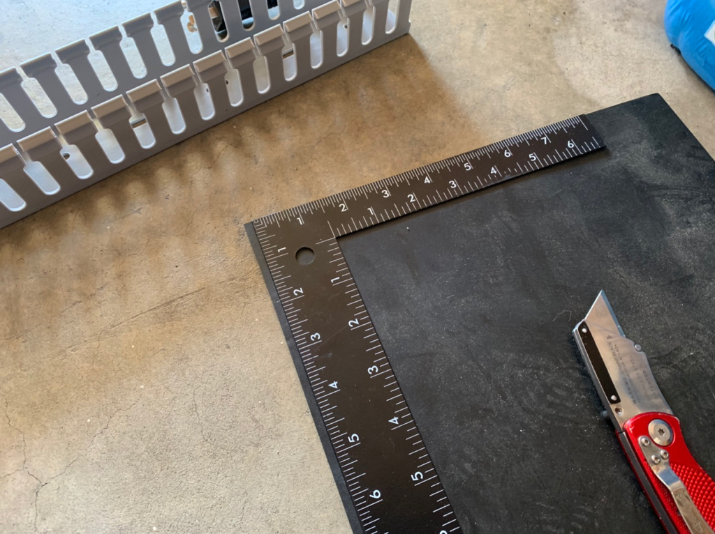
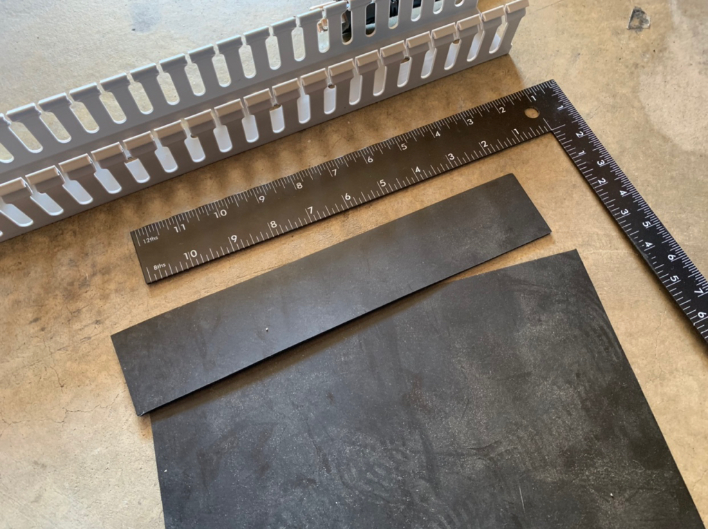
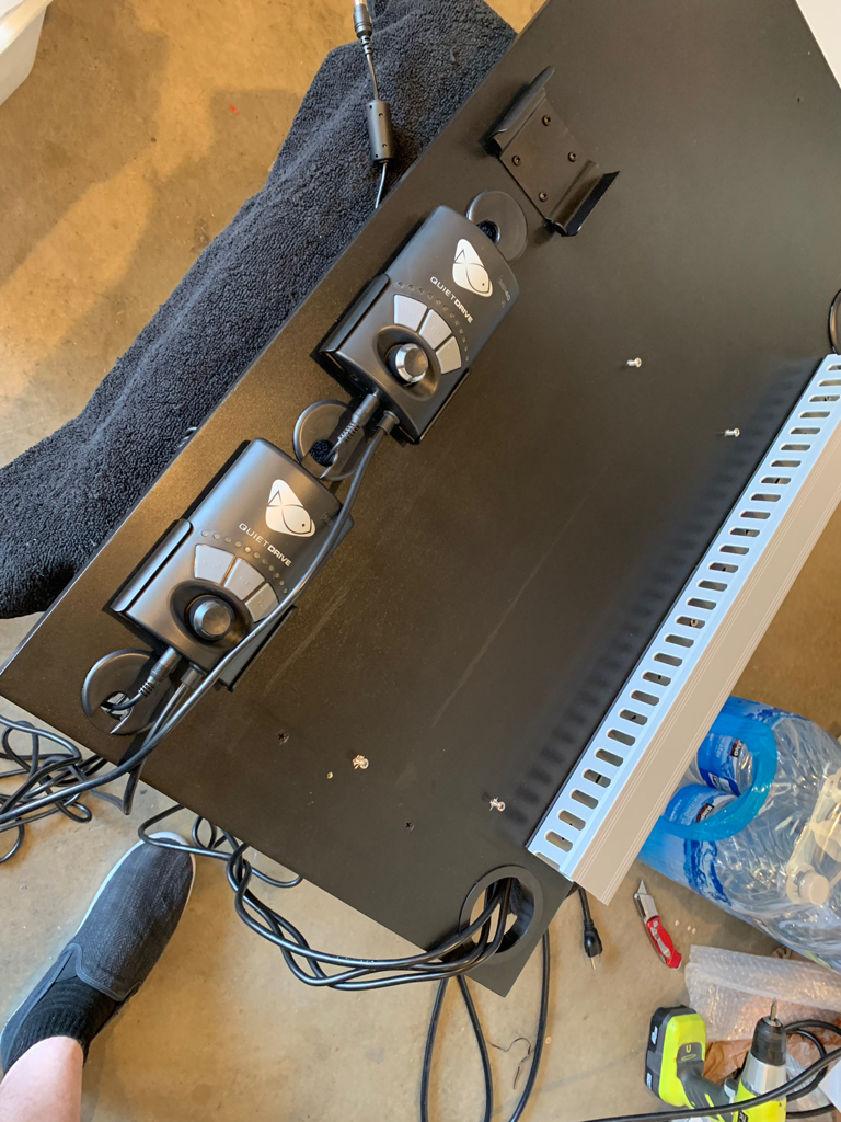
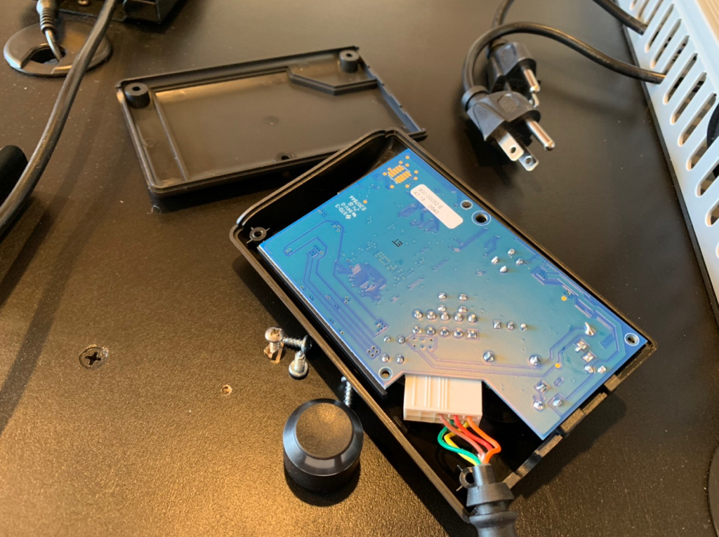
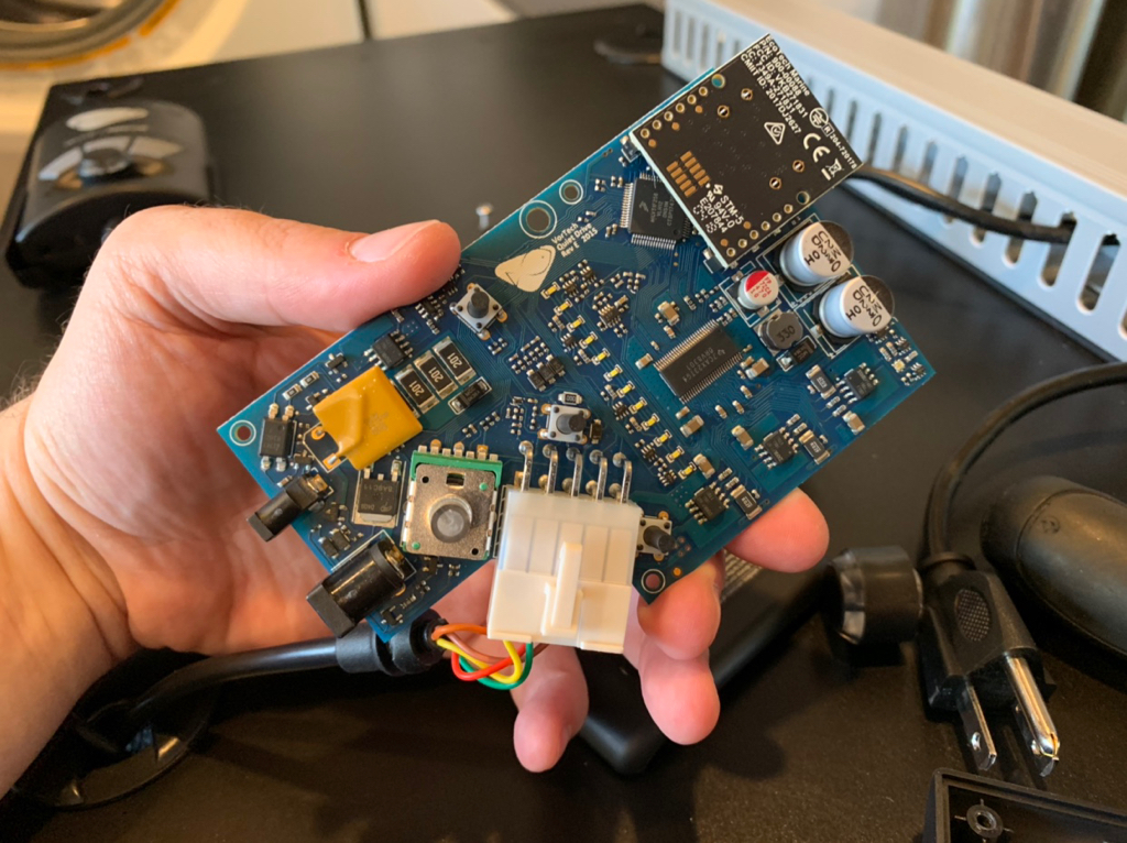
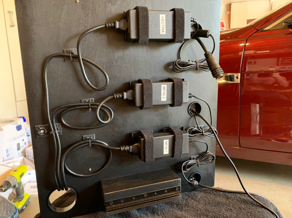
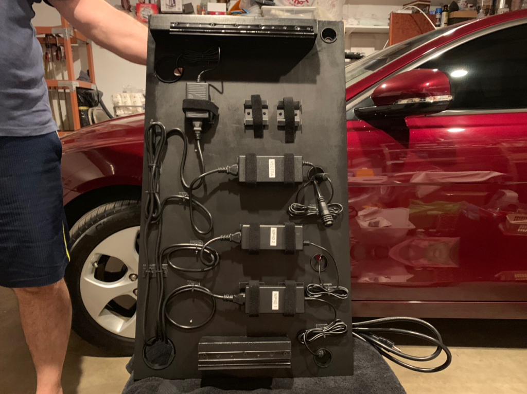
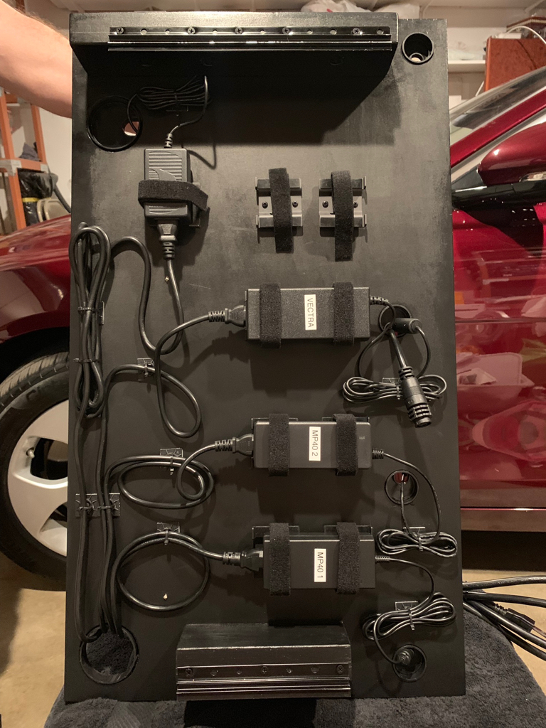
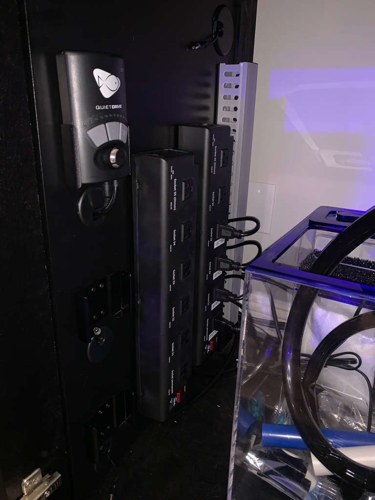
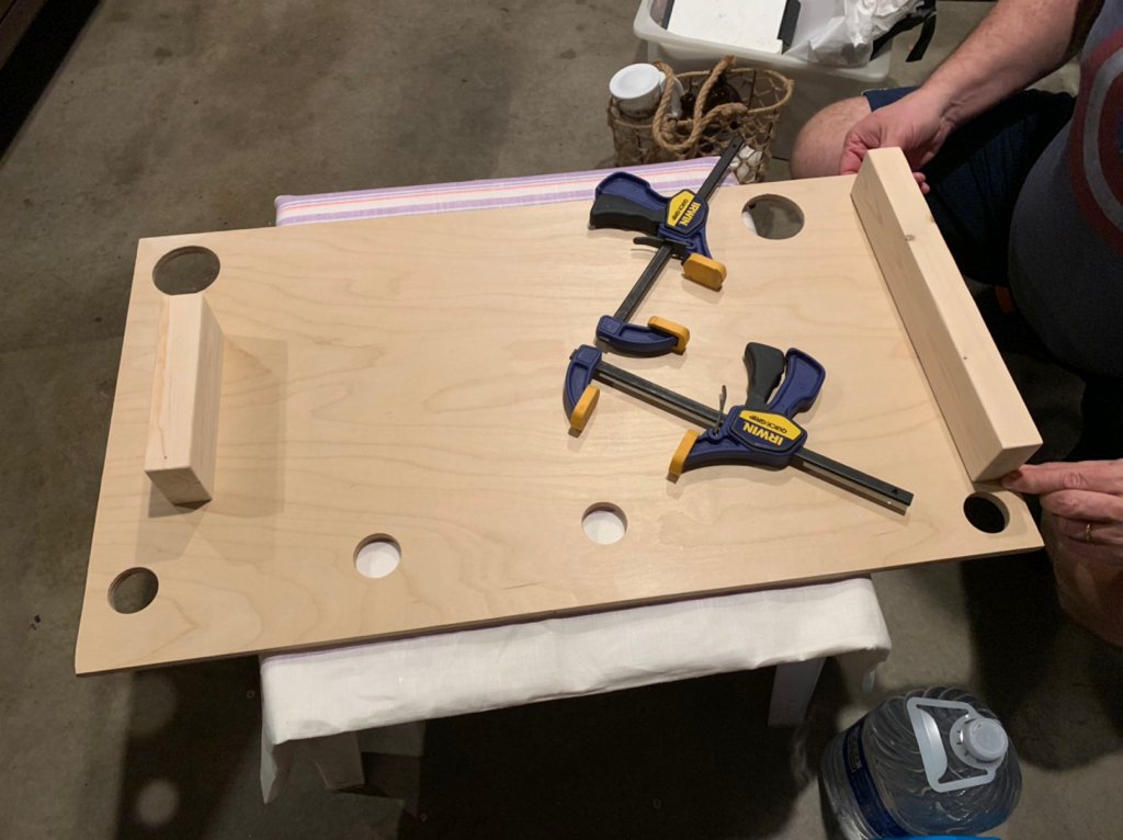
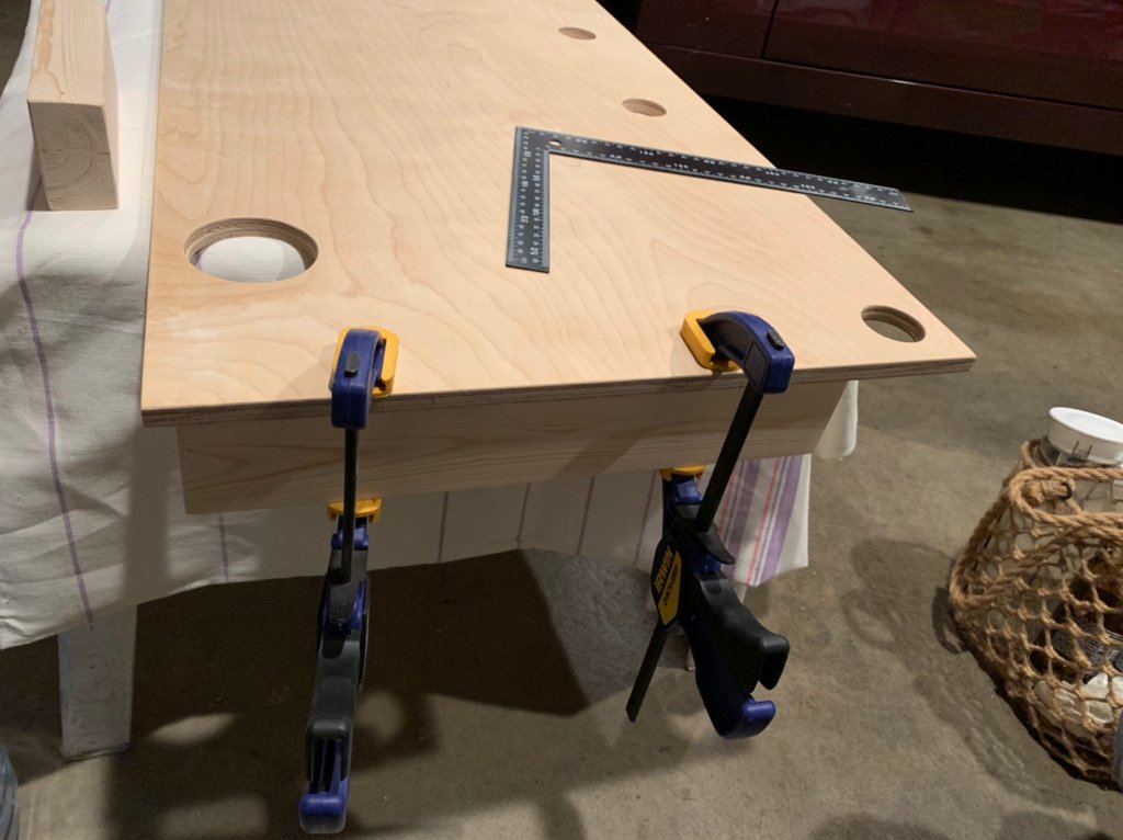
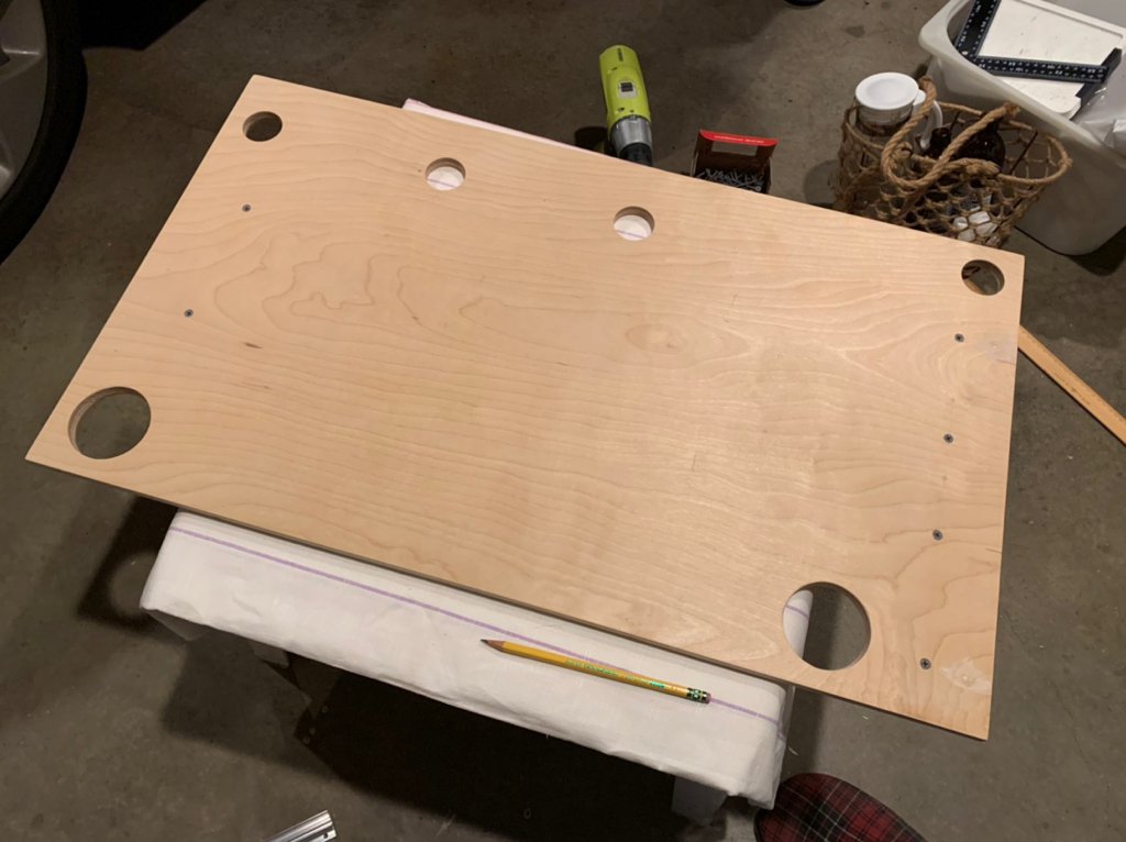
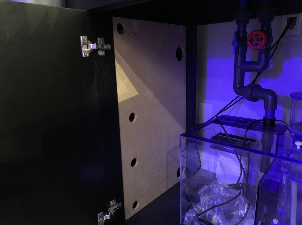
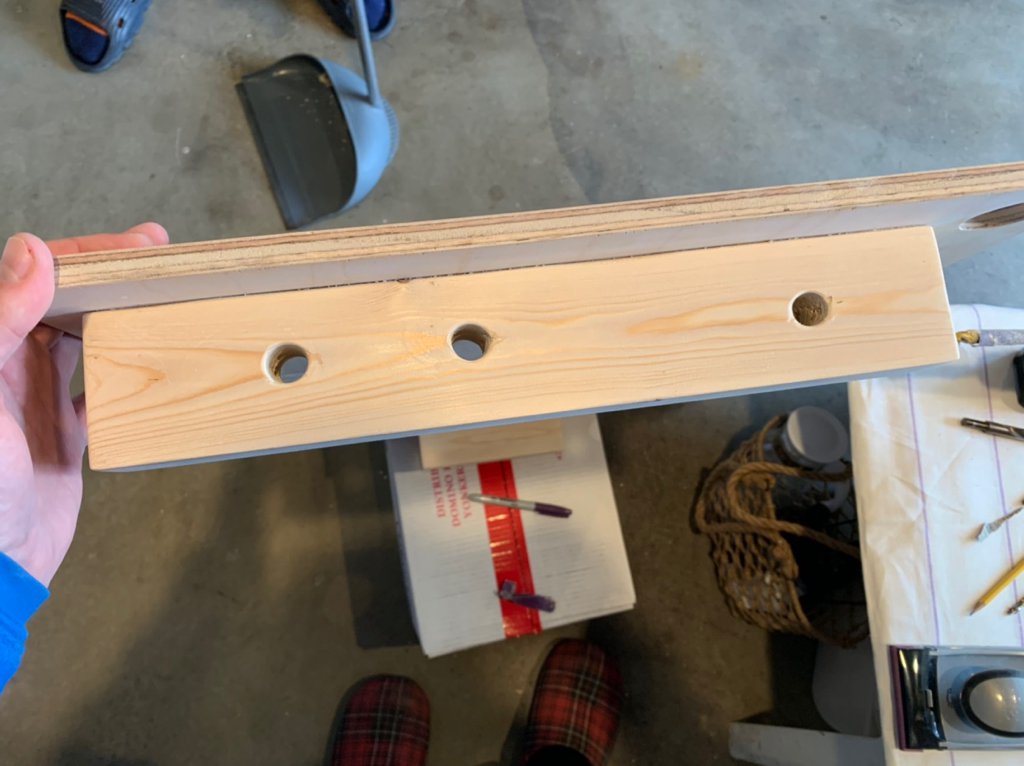
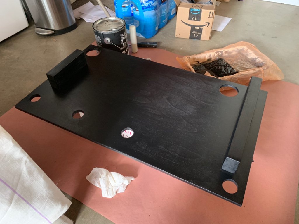
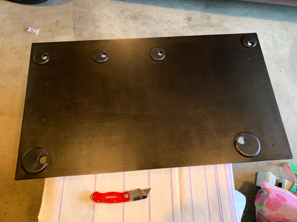
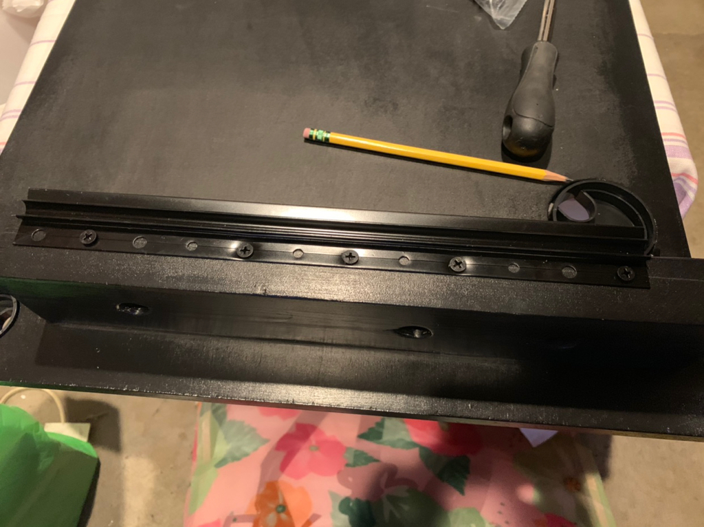
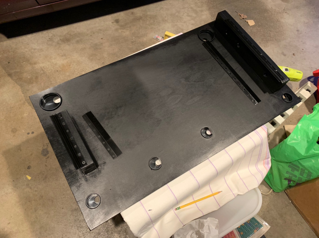
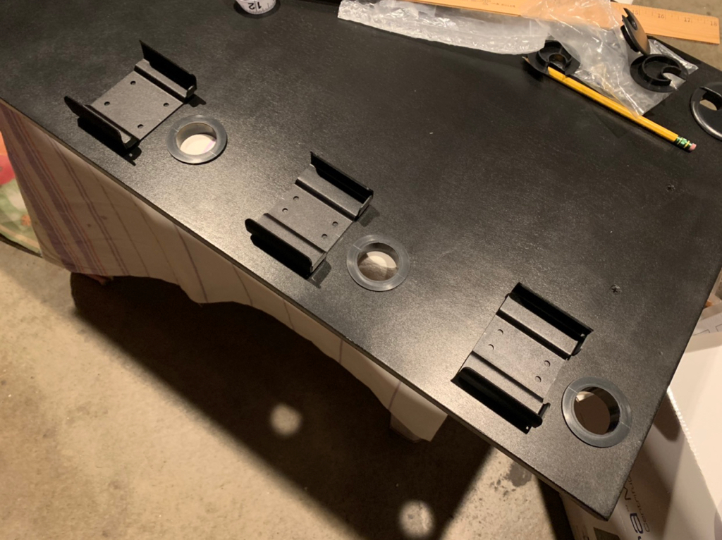
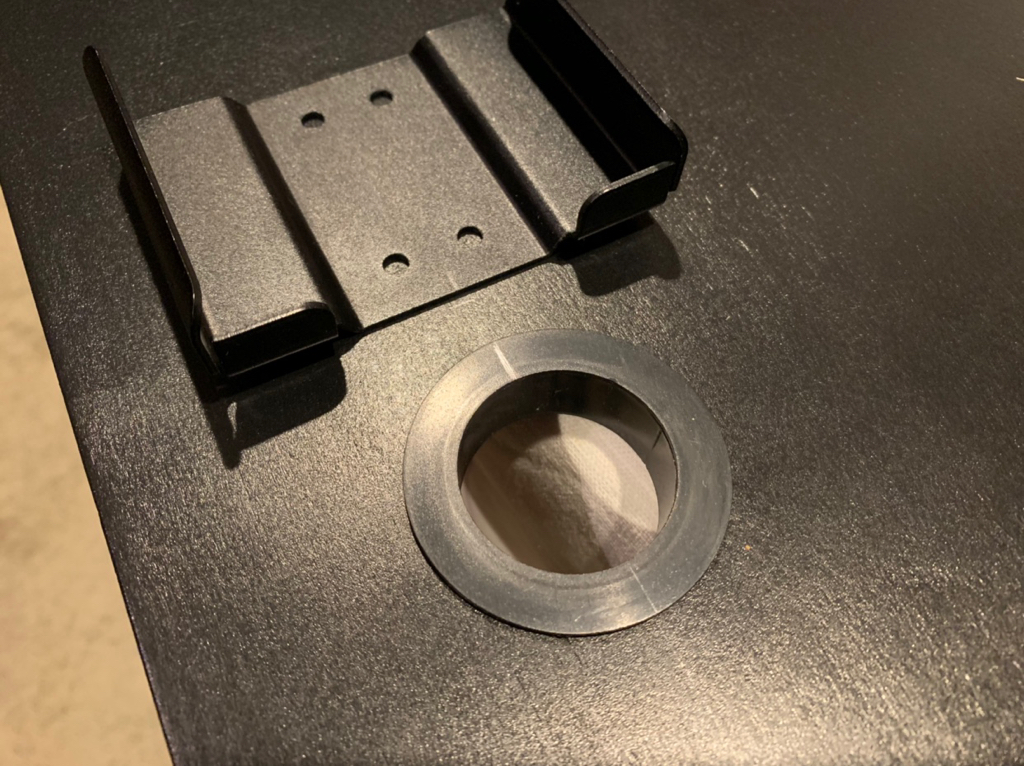
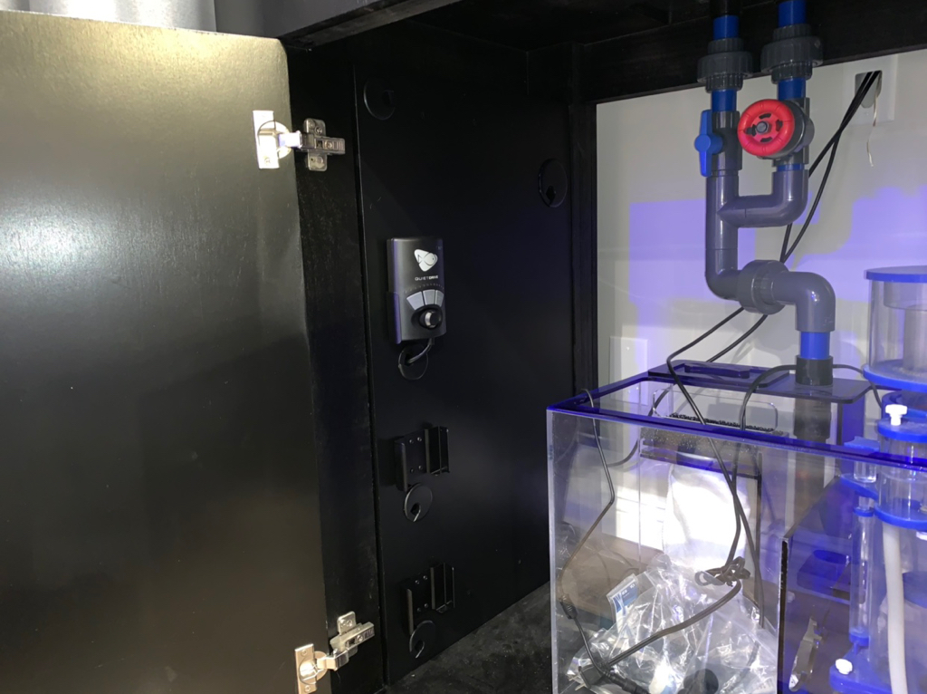
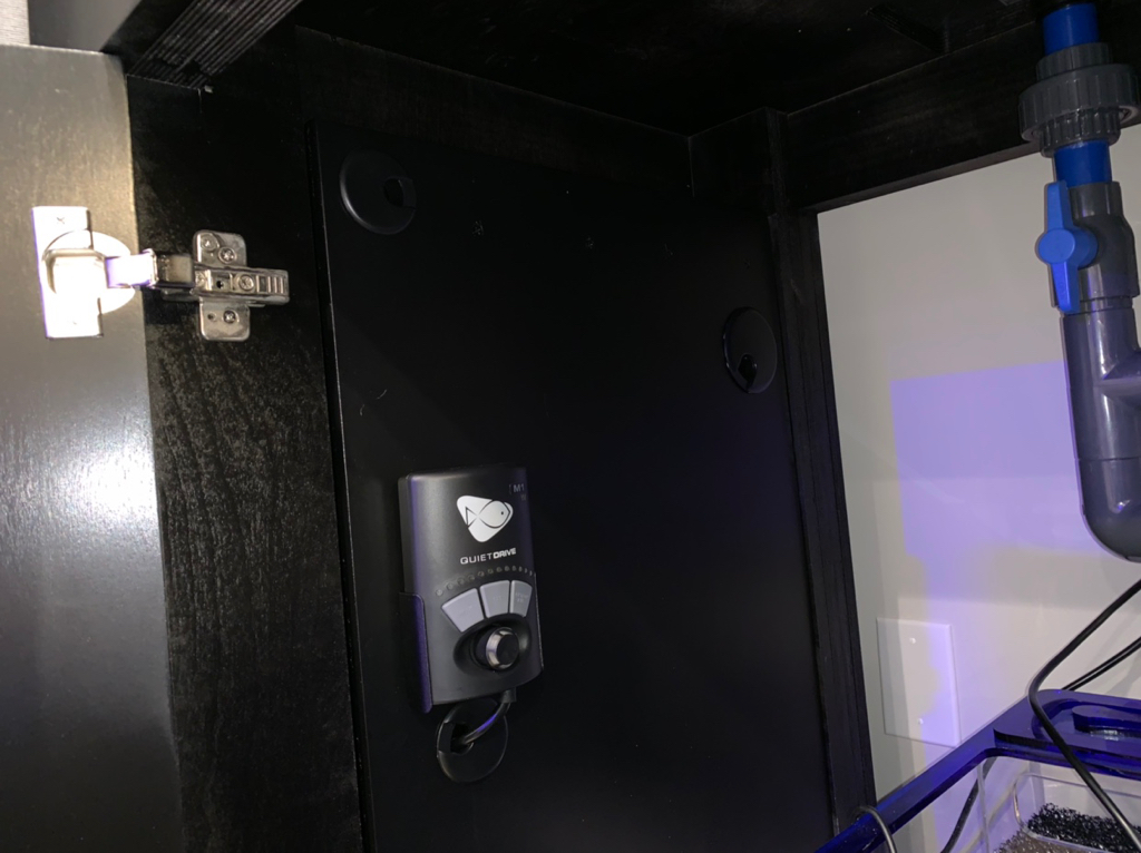
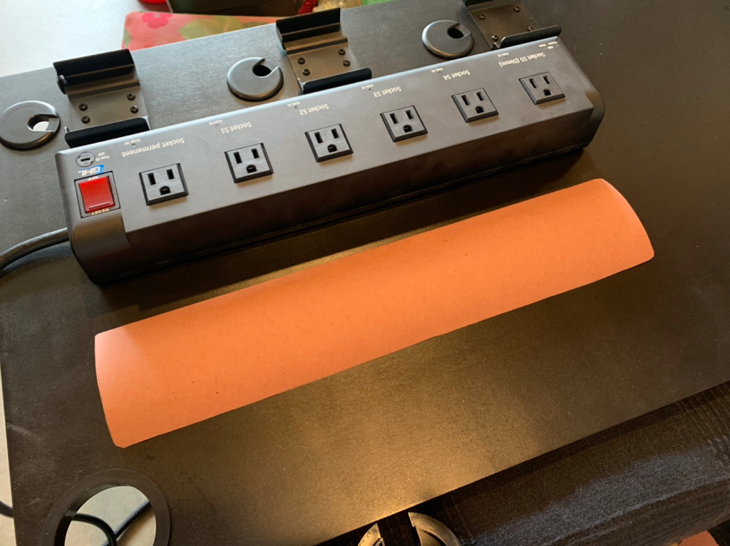
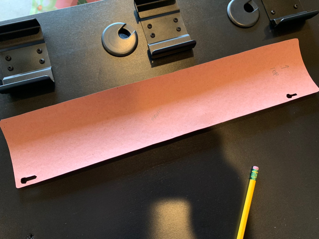
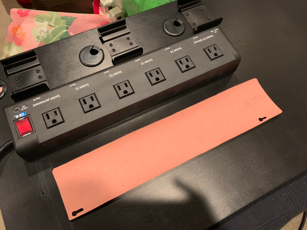
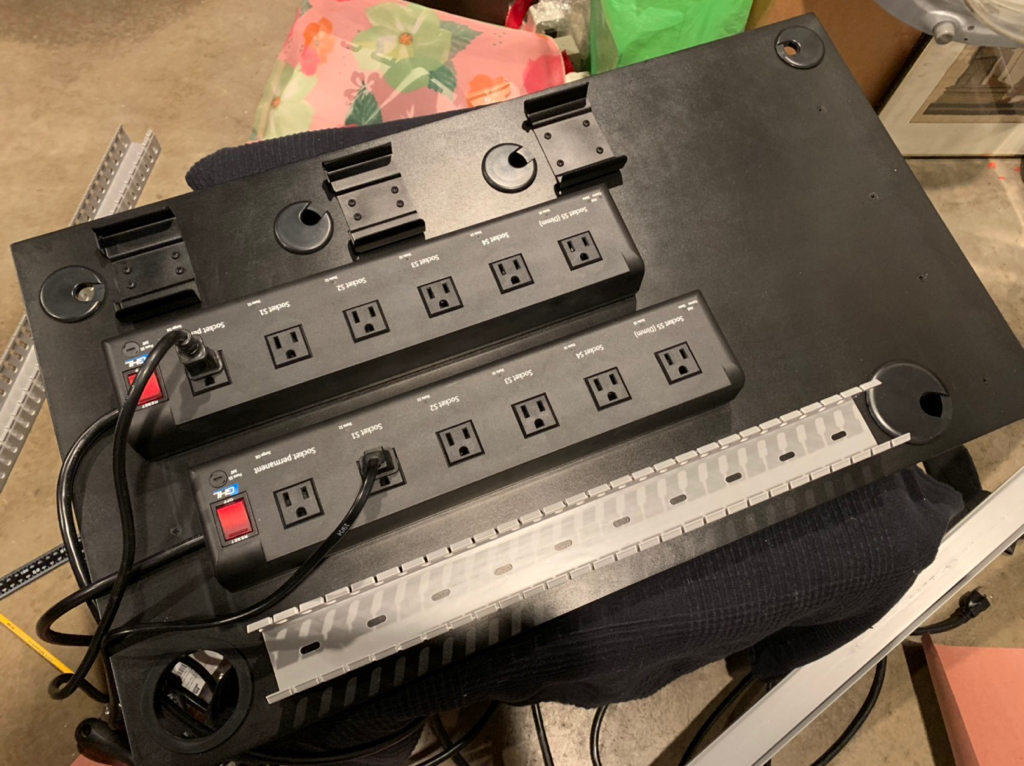
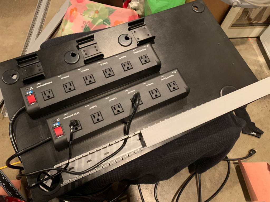
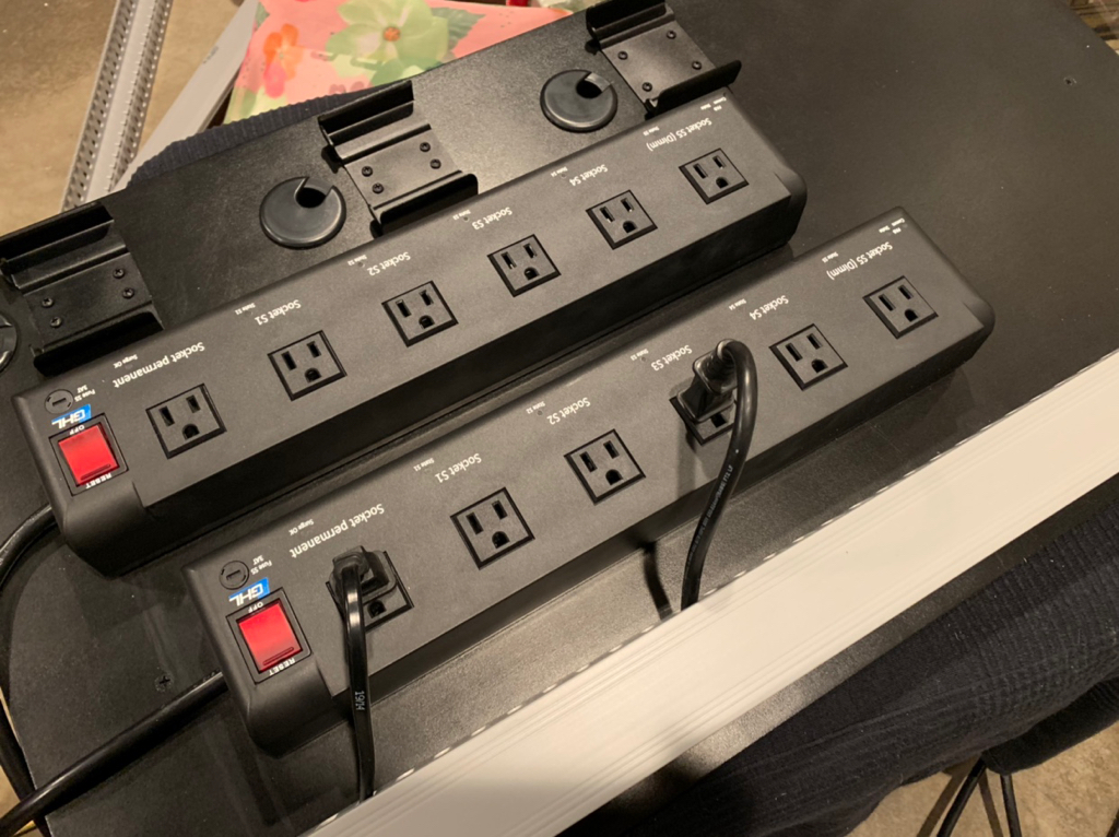
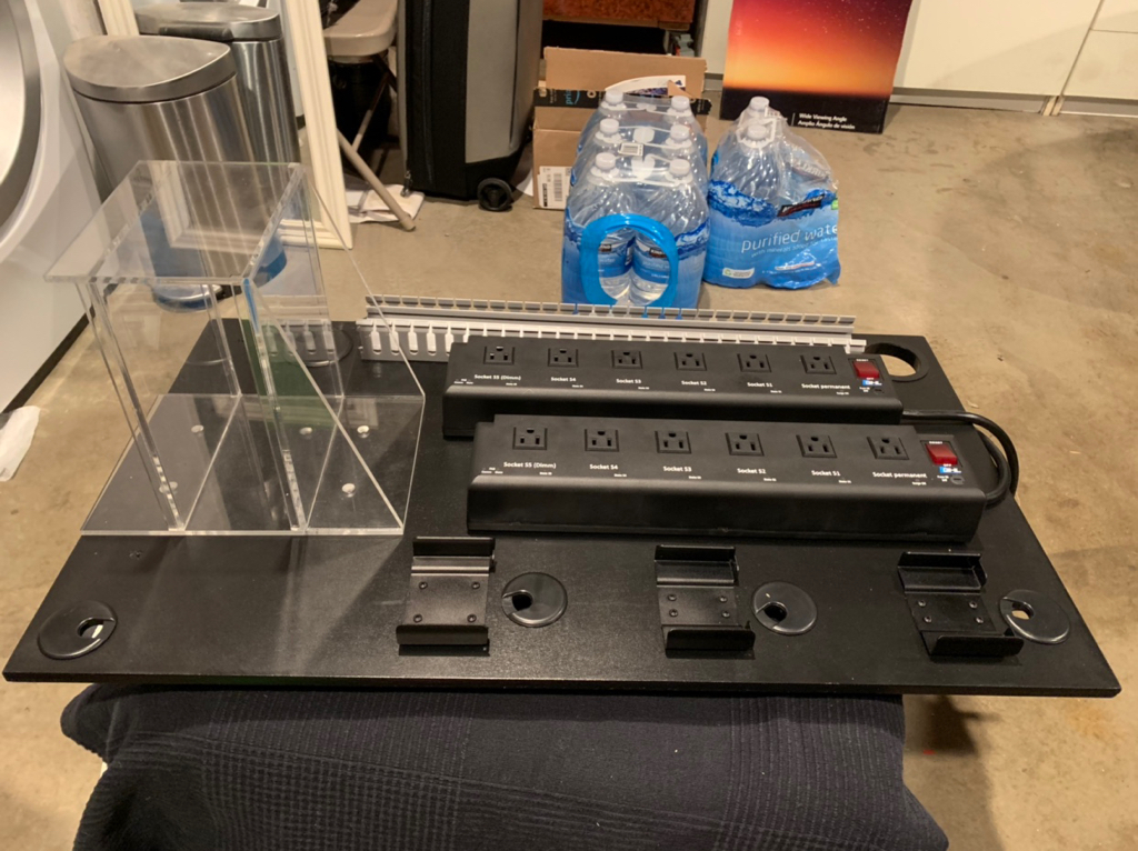
fantastic job detailing the process on this build! I especially appreciate the documentation of the controller mounting board, as I am working on one at the moment. looking forward to future updates.


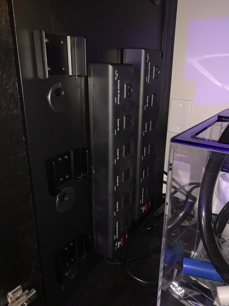
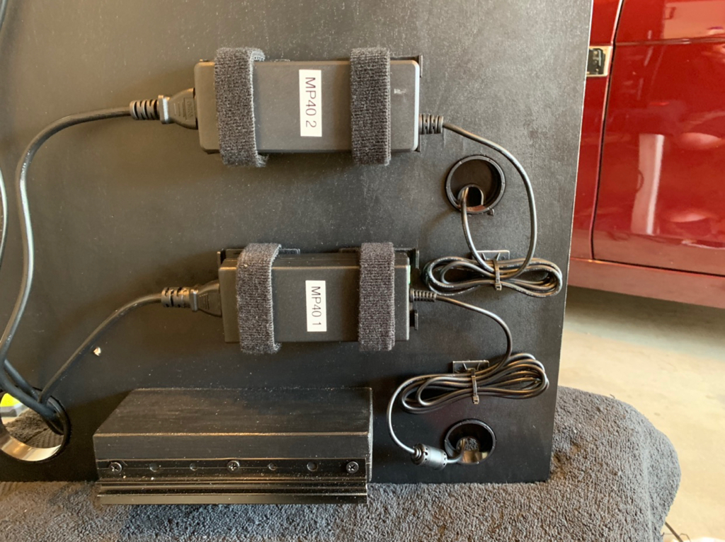
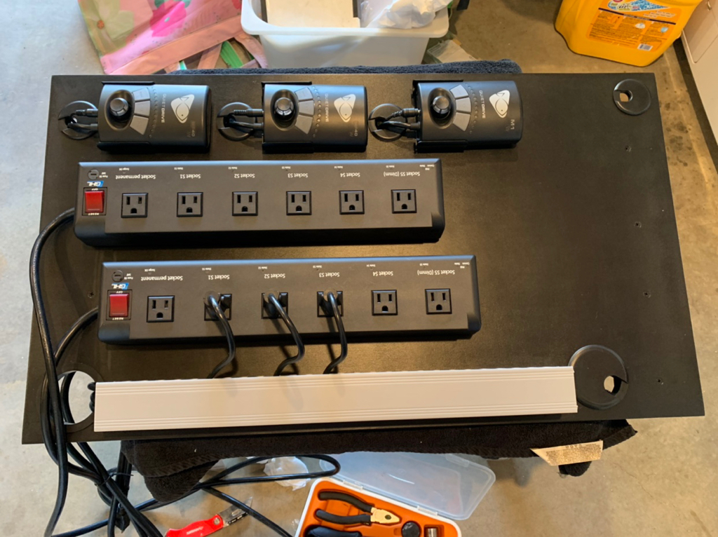
coming along nicely.
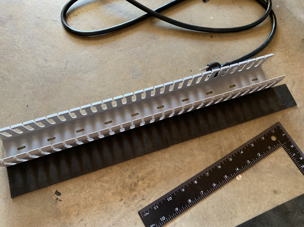
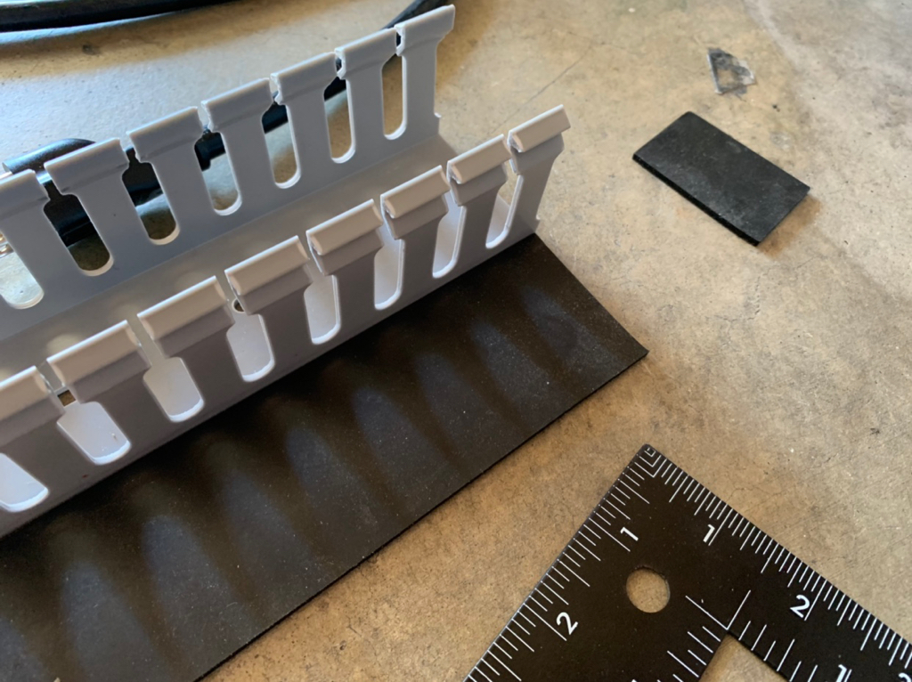
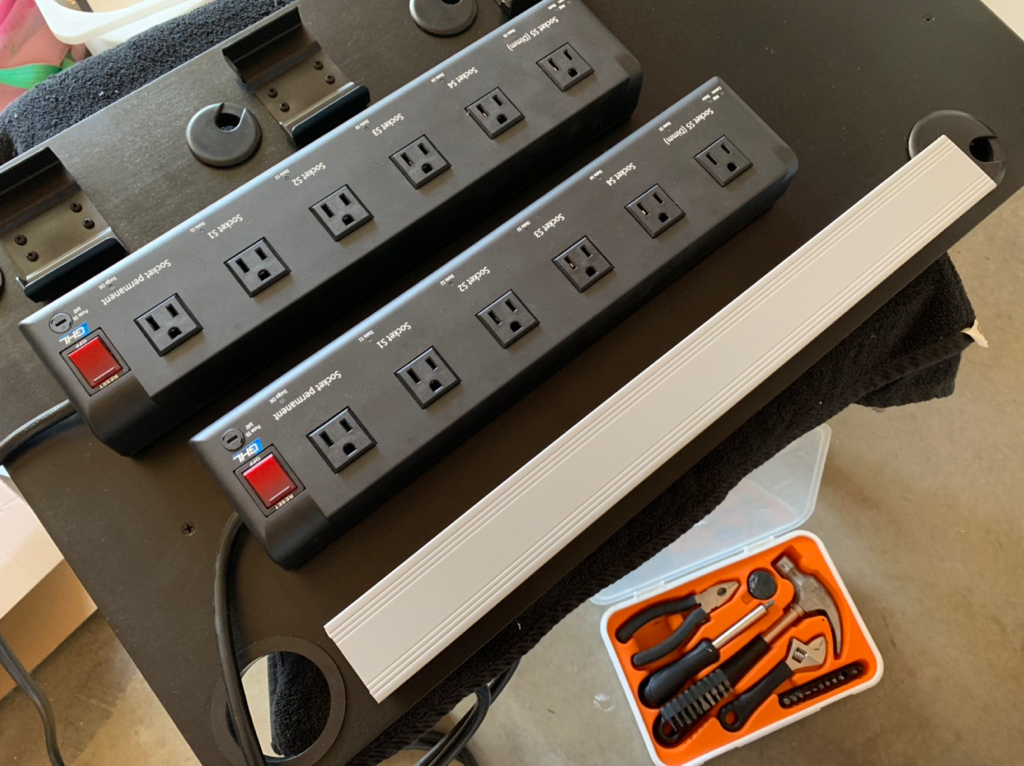
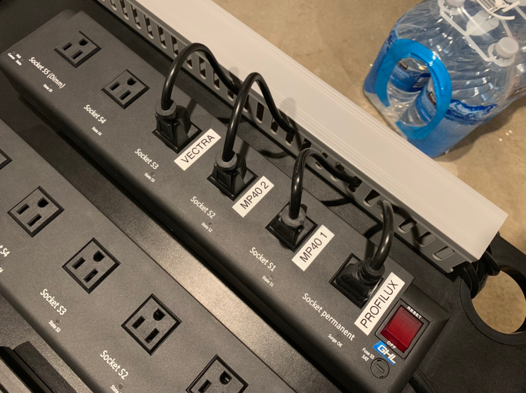
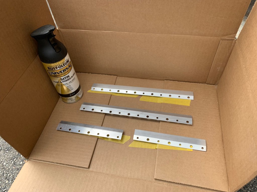
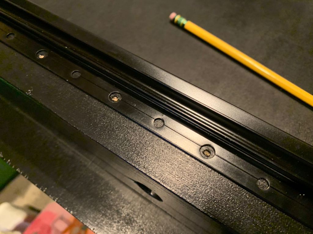
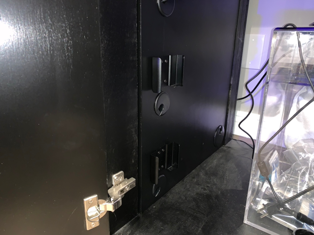
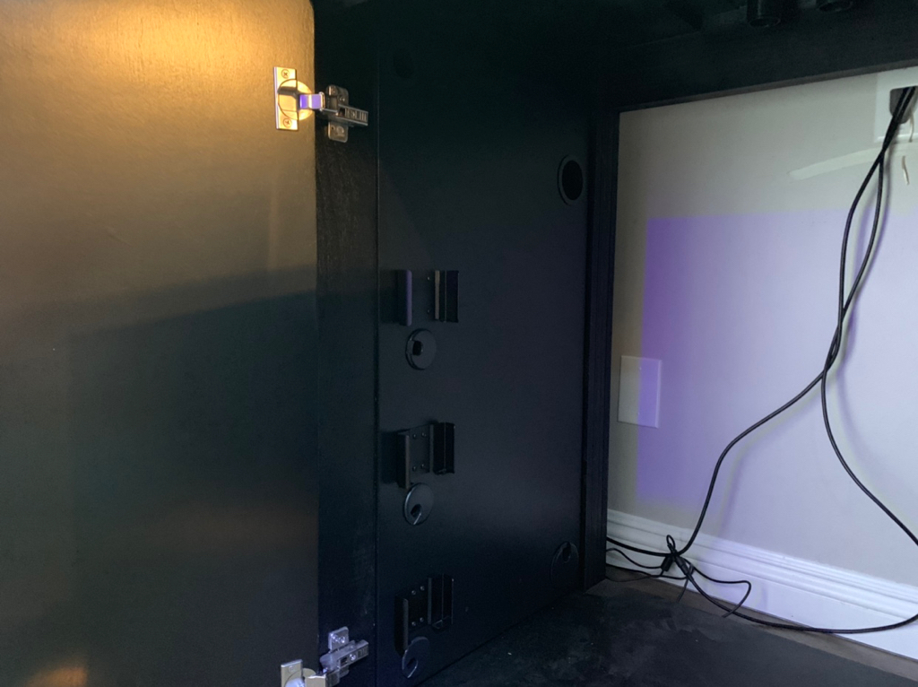
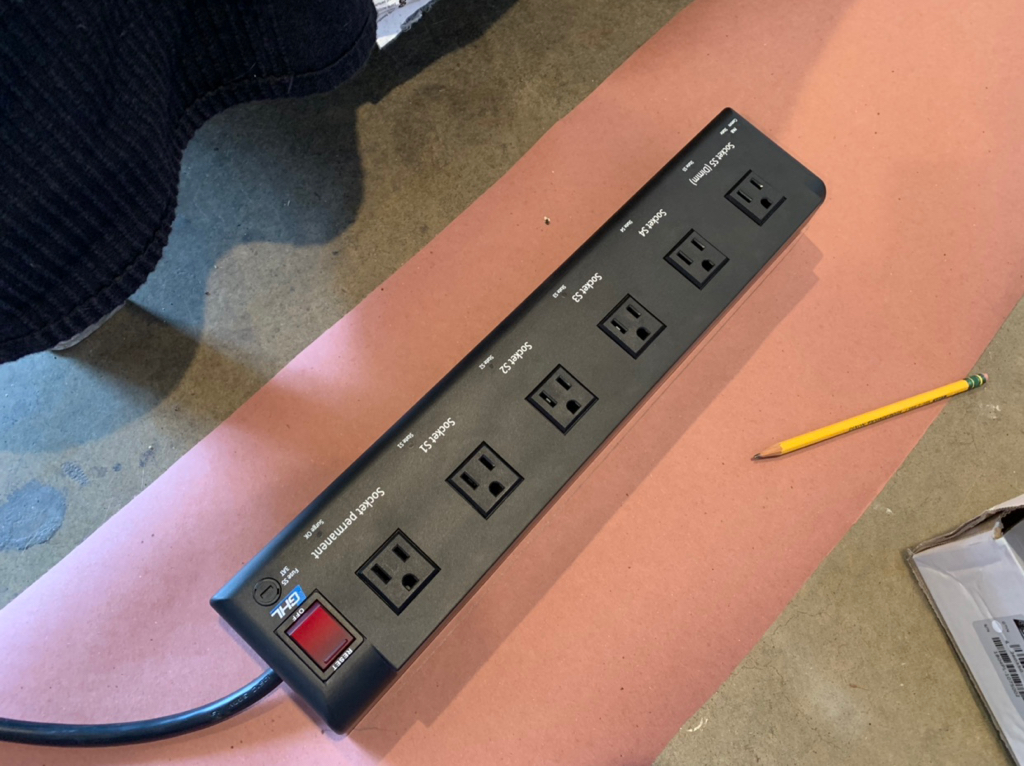
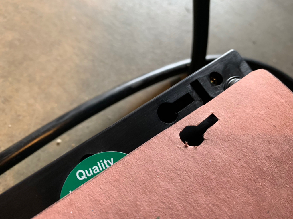
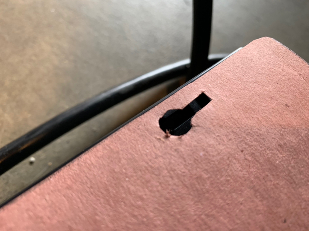
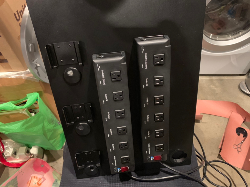
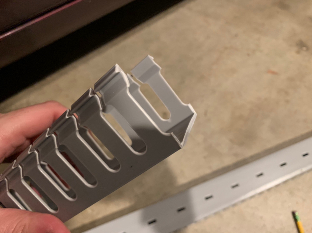
if I were you i'd paint that wire duct black with a quick coat of black spray paint. that way it'll be almost unnoticeable. just a thought considering all the time you've spent on it thus far!