All in One LED Controller/Dimmer/Driver Project

theatrus

Valuable Member
View Badges
Joined
Mar 26, 2016
Messages
1,952
Reaction score
3,353
Location
Sacramento, CA area
Rating - 0%
0   0   0
Over in the LEDBrick thread ( https://www.reef2reef.com/threads/ledbrick-diy-led-pendant-with-pucks.243746/page-5#post-5552632 ) I am experimenting with a mated driver and LED combo. After talking to a lot of people, I decided to do a bit of branching out experimentation to work with a more general purpose solution to the LED setup. This is based on the reality that people love experimenting with the LEDs and lighting its self, but the controller and driver has a more established requirement list ("boring" even). However, even if things are cut and dry, wiring and project complexity remains an on-going problem; integrating and wiring drivers and controllers with PWM is also a major headache.

So, what if we combine the controller/dimmer and LED drivers all into one nice modular box? Think of this as a super-sized LDD+Bluefish board, but in a fully open source design, with some enhancements.
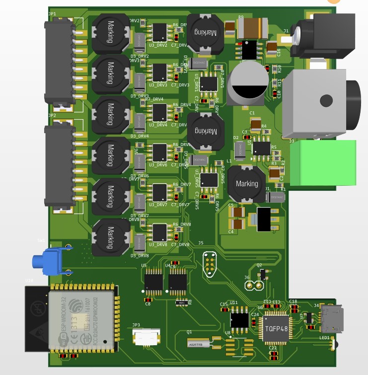
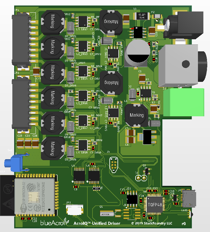
Concept:

sk1.png


This is an 8 channel design based on the LM3414HV, so up to 1A and 48V per channel (technically 60V but things get trickier for the rest of the design). It has dedicated power input connectors (2.1mm, power mini DIN, bare wire). More importantly, each channel is software programmable between 300-1000mA output (and can be dimmed). There is a USB connector for computer based programming, and an optional ESP32 module for WiFi connectivity. The brains are run on a easy to program ATSAMD21, and ESP32 is simply a connectivity slave. Included is an RTC and battery backup so it could run entirely stand-alone.

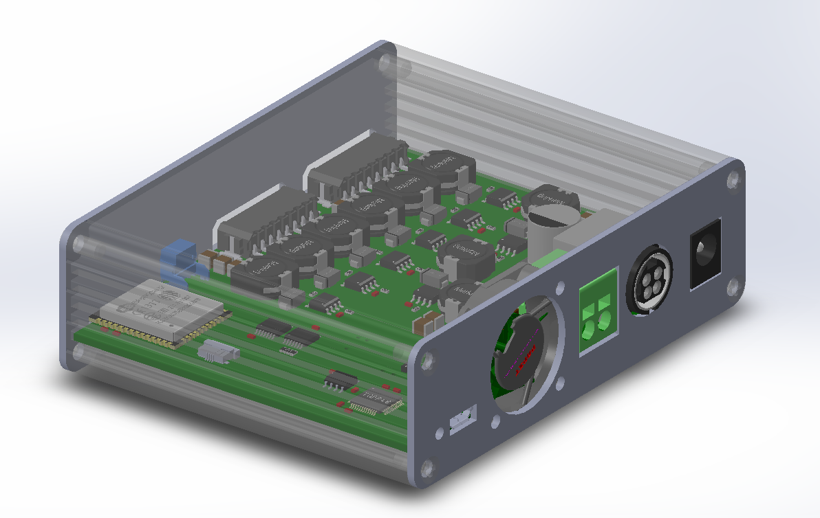
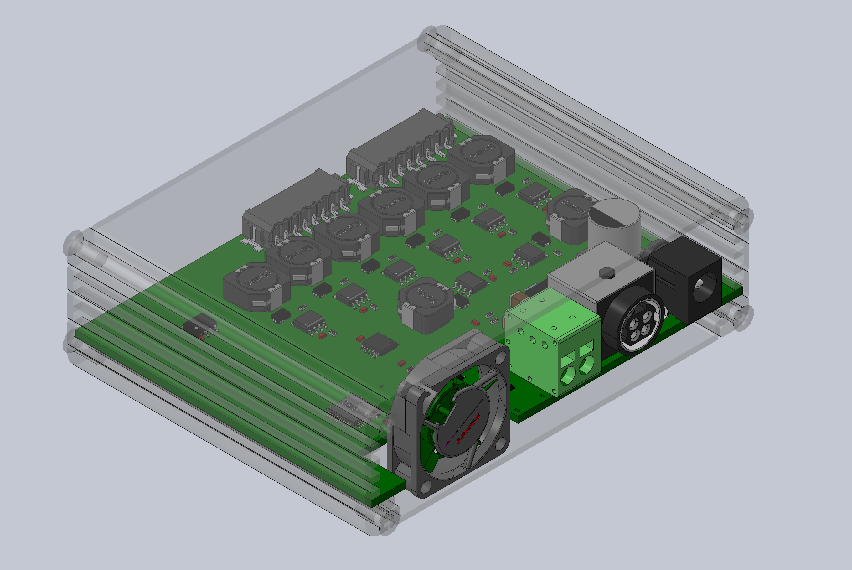
The case is a nice and compact:
case.jpg


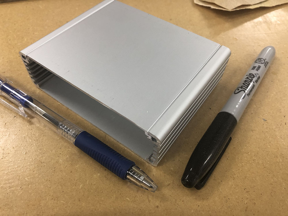
This design can be scaled using different drivers to 3A per channel.

Thoughts? Ideas?
 

rushbattle

Valuable Member
View Badges
Joined
Oct 19, 2016
Messages
1,347
Reaction score
1,644
Location
Equality
Rating - 0%
0   0   0
I don’t have anything to say other than I hope others can be more constructive and less ignorant than me, and I wish this were done about 4 months ago. Seems like the perfect solution for a bunch of scenarios.
 
OP
OP
theatrus

theatrus

Valuable Member
View Badges
Joined
Mar 26, 2016
Messages
1,952
Reaction score
3,353
Location
Sacramento, CA area
Rating - 0%
0   0   0
So you are writing your own software for this for the control I'm assuming?

Seems like a cool project.

Yes. I'm working on a framework for all of the Reef-Pi boards already, and this isn't that much of a leap software wise. Web connectivity is in a later phase.

There are a few callouts and open ended questions:
  • Focus on the 0-1A range, or the 0-3A (really 1.5-2A) range? You lose software current programmability on the upper end, meaning channels are locked to their configured maximum output.
  • Currently, the unit lacks any display for status outside of an RGB LED. I'm not keen on providing a whole programming interface in a tiny space, but is there interest in more ... visibility?
 

Kampo

Active Member
View Badges
Joined
Dec 19, 2017
Messages
349
Reaction score
327
Location
South West Michigan
Rating - 0%
0   0   0
I think if it was simple in non wifi mode as the old TC420 led controllers then I think that would be good. (basically just gave it a time and PWM value for that time for each channel.

maybe 1.5 amp? leave enough headroom for some bigger cobs?

display wise. led should be fine, but maybe a button for "emergency light" (its 3am and need a certain preset light to see something in a tank for 15min)
 
OP
OP
theatrus

theatrus

Valuable Member
View Badges
Joined
Mar 26, 2016
Messages
1,952
Reaction score
3,353
Location
Sacramento, CA area
Rating - 0%
0   0   0
I think if it was simple in non wifi mode as the old TC420 led controllers then I think that would be good. (basically just gave it a time and PWM value for that time for each channel.

maybe 1.5 amp? leave enough headroom for some bigger cobs?

display wise. led should be fine, but maybe a button for "emergency light" (its 3am and need a certain preset light to see something in a tank for 15min)

Let me see what I can whip up on that - good idea on an override button.
 

reeph

New Member
View Badges
Joined
Jan 31, 2019
Messages
16
Reaction score
31
Location
Austria
Rating - 0%
0   0   0
I have already built something similar, a All in One LED Controller based on an Arduino Pro Mini combined with a RTC, some LDD Drivers and a custom PCB. It works very well and is quiet simple, yet very useful. I also added a button to switch on the lights to a custom setting for a specified time in order to check the tank when needed. I have posted a picture of the PCB in another thread here on r2r. If you do not find it and need it, I can post it here again.

I also have some suggestions/thoughts for your project, which I also thought of to add to mine:

- Why do you want to make it battery driven? Everything at our tank is already connected to power, so I think it would be better to leave the batteries and have a smaller case and to use an additional power converter or power supply for the controller.
- Is there any specific reason why you prefer WiFi over BLE?

Concerning the PCB:
- It would be cool to also provide some PWM outputs beside the led channels. I am thinking about possibilities to control a fan for cooling the tank, a fan for cooling the lighting, ...
- Also providing one or two pins as an INPUT could be cool, as you could add additional temperature sensors or similar which could over WiFi provide you with information about your tank (I am just thinking in to the future :p)


Further, I would focus more on the 0-1A range (or max 1.5A range if possible). I think that it is better to use more LEDs which are driven with less current instead of fewer LEDs driven with 2A+, because the LEDs will live longer and you will be able to better distribute the LEDs on the heatsink.


I am curious about your answer to my suggestions :)
 
OP
OP
theatrus

theatrus

Valuable Member
View Badges
Joined
Mar 26, 2016
Messages
1,952
Reaction score
3,353
Location
Sacramento, CA area
Rating - 0%
0   0   0
I have already built something similar, a All in One LED Controller based on an Arduino Pro Mini combined with a RTC, some LDD Drivers and a custom PCB. It works very well and is quiet simple, yet very useful. I also added a button to switch on the lights to a custom setting for a specified time in order to check the tank when needed. I have posted a picture of the PCB in another thread here on r2r. If you do not find it and need it, I can post it here again.

I also have some suggestions/thoughts for your project, which I also thought of to add to mine:

- Why do you want to make it battery driven? Everything at our tank is already connected to power, so I think it would be better to leave the batteries and have a smaller case and to use an additional power converter or power supply for the controller.
- Is there any specific reason why you prefer WiFi over BLE?

Concerning the PCB:
- It would be cool to also provide some PWM outputs beside the led channels. I am thinking about possibilities to control a fan for cooling the tank, a fan for cooling the lighting, ...
- Also providing one or two pins as an INPUT could be cool, as you could add additional temperature sensors or similar which could over WiFi provide you with information about your tank (I am just thinking in to the future :p)


Further, I would focus more on the 0-1A range (or max 1.5A range if possible). I think that it is better to use more LEDs which are driven with less current instead of fewer LEDs driven with 2A+, because the LEDs will live longer and you will be able to better distribute the LEDs on the heatsink.


I am curious about your answer to my suggestions :)

No batteries involved - just a CR1216 for the RTC.

Why WiFi? I already have a BLE controller stack and ... development time in mobile apps sucks up most of the remaining free time I have. I’m not a super fan of IoT but it does cut down on Dev time. The WiFi portion is optional and parameter setting over USB is the default.

Agree on the push button. I do have a lot of vertical case space which could have a fan control slide in option if I add an internal connector.

Do you have a link to your thread?
 
OP
OP
theatrus

theatrus

Valuable Member
View Badges
Joined
Mar 26, 2016
Messages
1,952
Reaction score
3,353
Location
Sacramento, CA area
Rating - 0%
0   0   0
Worked on the layout for this a bit more. I've elected to put any further functionality on an optional daughter board, hence the FPC connector near the bottom left of the board.

sk2.jpg


Features:

8 Channels 350ma-1A (adjustable in software) + PWM dimming (high frequency), 12-48V input.
2 banks of 8 pin pluggable terminal blocks (easy to detach the controller from the wiring setup)
Three power inputs (barrel jack, 4 pin power DIN, bare wire)
USB programming
Push button
Optional Wifi/BLE via ESP32 module
Integrated case fan (cooler = happier electrons)
Optional expansion for temperature and fan control daughter card (plenty of space in the case)
 

reeph

New Member
View Badges
Joined
Jan 31, 2019
Messages
16
Reaction score
31
Location
Austria
Rating - 0%
0   0   0
Looks really nice! Do you already have some dimensions, how big the board will approximately be?
Do you want to implement a connectivity with an Android/iOS App to control the channels?
 
OP
OP
theatrus

theatrus

Valuable Member
View Badges
Joined
Mar 26, 2016
Messages
1,952
Reaction score
3,353
Location
Sacramento, CA area
Rating - 0%
0   0   0
Looks really nice! Do you already have some dimensions, how big the board will approximately be?
Do you want to implement a connectivity with an Android/iOS App to control the channels?

Board size is fixed by the case, 80x100mm. https://www.hammfg.com/part/1455L802

As for control from a mobile app, thats what the ESP32 as a bridge is hopefully ready to provide.
 
OP
OP
theatrus

theatrus

Valuable Member
View Badges
Joined
Mar 26, 2016
Messages
1,952
Reaction score
3,353
Location
Sacramento, CA area
Rating - 0%
0   0   0
Last edited:

brandon clow

Active Member
View Badges
Joined
Oct 22, 2017
Messages
121
Reaction score
155
Rating - 0%
0   0   0
Board size is fixed by the case, 80x100mm. https://www.hammfg.com/part/1455L802

As for control from a mobile app, thats what the ESP32 as a bridge is hopefully ready to provide.


I like these cases, I have a bunch of similar ones at work with a matching aluminum end caps. They work great for my CAN/LIN boards and other cobbled CAN data collection devices.
 
OP
OP
theatrus

theatrus

Valuable Member
View Badges
Joined
Mar 26, 2016
Messages
1,952
Reaction score
3,353
Location
Sacramento, CA area
Rating - 0%
0   0   0
I like these cases, I have a bunch of similar ones at work with a matching aluminum end caps. They work great for my CAN/LIN boards and other cobbled CAN data collection devices.

In my case I’m using PCBs as end caps. Weird economies of scale make this the cheapest for a printed machined end cap :)

Plus if I leave copper on them they act as a nice shielded case.
 

Caring for your picky eaters: What do you feed your finicky fish?

  • Live foods

    Votes: 17 28.3%
  • Frozen meaty foods

    Votes: 50 83.3%
  • Soft pellets

    Votes: 9 15.0%
  • Masstick (or comparable)

    Votes: 6 10.0%
  • Other

    Votes: 3 5.0%
Back
Top