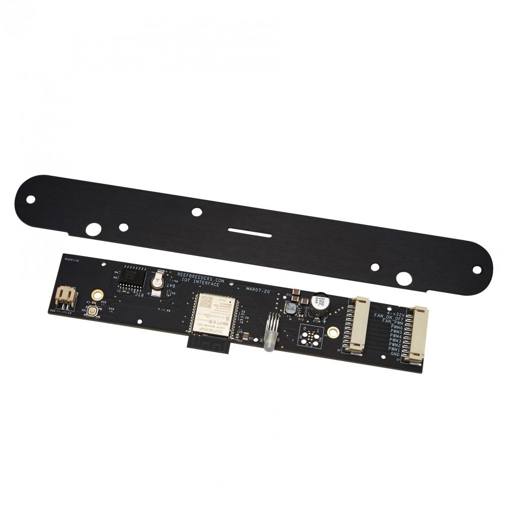
Control reefbreeders photon v2 pro with reef-pi?

waynel

Active Member
View Badges
Joined
May 22, 2020
Messages
264
Reaction score
266
Location
Kentucky
Rating - 0%
0   0   0
Anyone done this or know if the photon v2 pro lights with the vdk module installed can be controlled via reef-pi? I believe the vdk module gives the lights 0-10v capability.
 
OP
OP
waynel

waynel

Active Member
View Badges
Joined
May 22, 2020
Messages
264
Reaction score
266
Location
Kentucky
Rating - 0%
0   0   0
I was not able to get any details on the Vdk module, hard to confirm without the specs.
From some pictures I've found googling, the pinout of the vdk module is:
Pin Function
3 gnd
4 0-10v port
7 gnd
8 0-10v port

and there are 3 ports on the module, 6 channels.
 

theatrus

Valuable Member
View Badges
Joined
Mar 26, 2016
Messages
1,951
Reaction score
3,353
Location
Sacramento, CA area
Rating - 0%
0   0   0
From some pictures I've found googling, the pinout of the vdk module is:
Pin Function
3 gnd
4 0-10v port
7 gnd
8 0-10v port

and there are 3 ports on the module, 6 channels.

If it just wants 0-10V, it should be easy to just feed it 0-10V. Don't see a problem with it.
 

dustbuckets

New Member
View Badges
Joined
Jul 21, 2010
Messages
1
Reaction score
0
Location
usa
Rating - 0%
0   0   0
I was just wondering about this a couple days ago too! Would be very interested to see if this works.
 

Coolhack

Community Member
View Badges
Joined
Jul 21, 2019
Messages
80
Reaction score
50
Location
Anywhere
Rating - 0%
0   0   0
Did you get this working? I just got the 48in photon v2 w/o the internet controller. I opened it up and took some pics of the inside.
 

Sral

Valuable Member
View Badges
Joined
May 2, 2022
Messages
1,006
Reaction score
976
Location
Germany
Rating - 0%
0   0   0
Just saw this one, sry ^^

Judging from your photos and the text on their website about the Apex VDM Kit its doable, as @theatrus said.

First important photo, the main control circuit has 6 "PW" channels for the 6 color channels, as described in the link above:
20220912_211630-jpg.2826085


The standard photon v2 has a wireless remote with LCD screen, as described in the text in the link above, which is probably what this board at the end is for:
20220912_211707-jpg.2826087

This is at the exact same place and has the exact same plug layout as the APEX VDM module that you can install there.
So my guess is: this interfaces with your remote and simply outputs the PWM or PW signals for the main board.

If you look at the Apex VDM integration board in the link, you also see that it's very simple, just a few resistors, capacitors and and two IC that probably handle the zeroing discussed in the video.

Only problem I see is that the Temperature probe is also connected to this board, which therefore controls the fans.

So two ways forward:
- build the VDM integration kit yourself (difficult due to the Fan control)
----> you would need to know how the fan signal needs to behave
----> you would need to know if the main board expects a 10V PWM, or a 0-10V DC signal
- buy the Apex VDM integration kit and feed it from Reef-Pi
----> you would still need to know the approximate frequency of the PWM signal

In both cases I would at least try to contact the manufacturer. My Light was build by a comparatively small-ish upstart company here in germany and they were very forthcomming with advice for Reef-Pi integration, even though they never heard of it ^^
 

oreo54

5000 Club Member
View Badges
Joined
Sep 18, 2017
Messages
5,583
Reaction score
3,438
Rating - 0%
0   0   0
Not sure you need to bother w/ the vdm module
Just identify the driver ic on the big center board.
That will give you the dimming protocol.

Basically discard the " control board" and replace it w/ the reef pi.

Pretty sure the vdm module converts 10v to whatever the drivers want

Fan circuit may or may not be a problem.
Could be independent thermistor controlled unit..or not.

Anyway key is what does the orig brain board send to the drivers?

Vdm showing conversion from 10 v analog to some flavor of pwm
I'd bet 5v-ish.

Screenshot_20221006-223545.png


Interesting .
 
Last edited:

oreo54

5000 Club Member
View Badges
Joined
Sep 18, 2017
Messages
5,583
Reaction score
3,438
Rating - 0%
0   0   0
Actually no need to find the driver ic..Upgrade board sort of defines the driver PWM.
rbreeders.JPG

Left end (not shown) has a plug for a temp sensor.
ESP32 has a built in temp input.
 
Back
Top