DIY ATO (Automatic Top Off) Controller

oldchoppy

New Member
View Badges
Joined
Jul 25, 2019
Messages
12
Reaction score
19
Location
Plant City
Rating - 0%
0   0   0
The thread will document the creation of a DIY ATO for my display tank, but will work in a sump. The focus is primarily a learning exercise because I am still new to the hobby and enjoy an electronics DIY project. This project contains a custom circuit board design that can be sent to PCB companies for fabrication.

The design and documentation are intended to be open source, so I will post information regarding design decisions, materials lists, and design documents. Also, I am interested in feedback for adding additional features to the design because this is a learning experience after all!

The following board should be shipped this weekend and I will post pictures during assembly. I have not tested this design yet and will post the results.

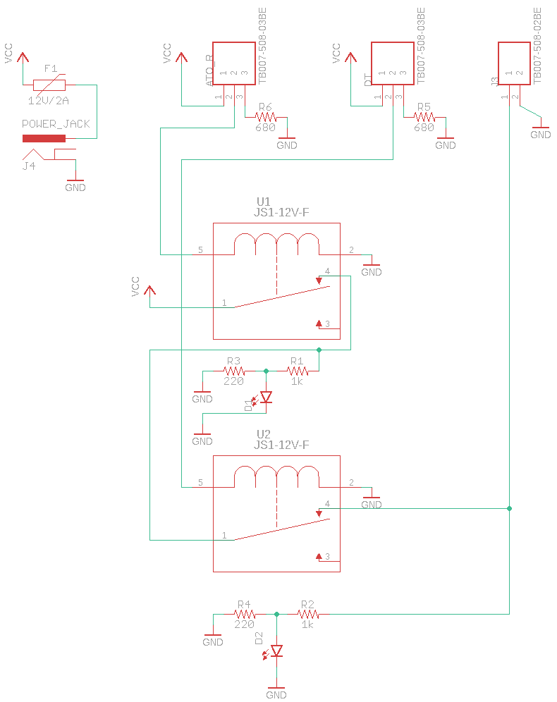
Board Layout and Schematic:
Board Layout.png

schematic-png.1460409


Basic Design Details:
  • 12V DC Operating Voltage
  • 2A Fuse Protection
    • Traces are oversized at 70mil. I treated them as an internal layer because my enclosure does not have good ventilation with a temp rise of 10 degrees C and 3 Amp current in case the fuse needs time to catch an issue.
  • Compatible with DC pumps rated 12V @ under 2A
    • 12V peristaltic dose pumps work
    • 12V submersible centrifugal pumps work as well, I will use one with a check valve
  • Compatible with optical level sensors
    • The logic (NO/NC) is important right now because I have not implemented jumpers to change the relay logic, this is a possible change to add.
  • Compatible with float reed switches
    • The logic (NO/NC) is important right now because I have not implemented jumpers to change the relay logic, this is a possible change to add.
  • I use aviation connectors because they are cheap, but the wires could be directly soldered or other connectors could be used.
Theory of Operation:
  1. When water level in the display tank (or sump) is low, change the signal to close the first pump control relay allowing the pump to run.
  2. When water level in the display tank (or sump) is high, change the signal to open the first pump control relay preventing the pump to run.
  3. While water level in the RO(DI) makeup reservoir is high, close the second pump control relay allowing the pump to run.
  4. While water level in the RO(DI) makeup reservoir is low, open the second pump control relay preventing the pump to run dry.
Schematic.png
 

Attachments

  • License.pdf
    80.8 KB · Views: 79
  • eagle_cad.zip
    26.5 KB · Views: 57
  • Board BOM.xlsx
    15.4 KB · Views: 108

Bigtrout

Valuable Member
View Badges
Joined
Dec 16, 2018
Messages
1,189
Reaction score
2,826
Rating - 0%
0   0   0
Nice work on a good solution for an ATO. Looks like you have all your bases covered. The only way to make this better would be to use relays with more contacts so you could implement a circuit with a holding contact to give yourself a bit of hysteresis. That way wave action wouldnt affect sensors as much in the display tank.
 

theatrus

Valuable Member
View Badges
Joined
Mar 26, 2016
Messages
2,011
Reaction score
3,400
Location
Sacramento, CA area
Rating - 0%
0   0   0
Looks good, a few odds and ends for version 2 which should improve reliability:

- Its always a good idea to put a flyback diode across any coils. The high voltage pulse across relay coils can cause arcing back on your float switches.
- Avoid uses small float switches with any amount of current across their terminals, especially DC. They tend to arc weld themselves closed :). Use a transistor or FET to switch the relay based on the signal from the float switch.

Also, why is your LED in a resistor divider? You only need to set the current through the LED based upon the voltage (12V), minus the the Vf of the LED. You can omit those 220ohm resistors.
 
OP
OP
oldchoppy

oldchoppy

New Member
View Badges
Joined
Jul 25, 2019
Messages
12
Reaction score
19
Location
Plant City
Rating - 0%
0   0   0
Nice work on a good solution for an ATO. Looks like you have all your bases covered. The only way to make this better would be to use relays with more contacts so you could implement a circuit with a holding contact to give yourself a bit of hysteresis. That way wave action wouldnt affect sensors as much in the display tank.
Thanks! I appreciate the feedback. Reducing the amount of energization due to waves would be very helpful. I'll start brainstorming some circuits.
 
OP
OP
oldchoppy

oldchoppy

New Member
View Badges
Joined
Jul 25, 2019
Messages
12
Reaction score
19
Location
Plant City
Rating - 0%
0   0   0
Looks good, a few odds and ends for version 2 which should improve reliability:

- Its always a good idea to put a flyback diode across any coils. The high voltage pulse across relay coils can cause arcing back on your float switches.
- Avoid uses small float switches with any amount of current across their terminals, especially DC. They tend to arc weld themselves closed :). Use a transistor or FET to switch the relay based on the signal from the float switch.

Also, why is your LED in a resistor divider? You only need to set the current through the LED based upon the voltage (12V), minus the the Vf of the LED. You can omit those 220ohm resistors.
I will add flyback diodes on the next revision. The reason I chose to run the coil from the float switch was based on the specification sheets. The coil uses 30ma at 12v to switch. Meanwhile the switch is rated for 500ma switching current. I did not realize arcing could cause a failure mode like that and I can see how the life of the switch would be extended. Thanks for the info!

The LED's I had laying around were rated for roughly 3V. I added the voltage dividers to bring 12V down to just under 3V at the right current. For some reason, I thought I needed to limit the voltage into the LED as well as current. I will test this on a breadboard with the LED's. I'll remove them in the next version if I can.
 

Making aqua concoctions: Have you ever tried the Reef Moonshiner Method?

  • I currently use the moonshiner method.

    Votes: 16 23.2%
  • I don’t currently use the moonshiner method, but I have in the past.

    Votes: 0 0.0%
  • I have not used the moonshiner method.

    Votes: 51 73.9%
  • Other.

    Votes: 2 2.9%
Back
Top