
I decided to purge my ACR today and when starting back up, had some interesting results.
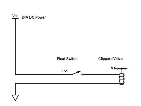
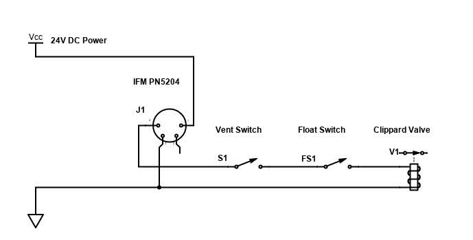
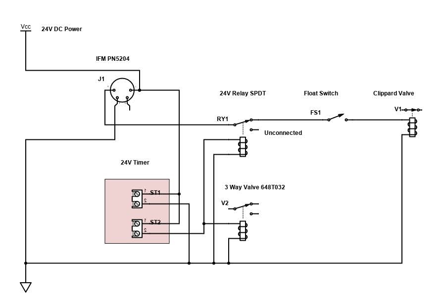
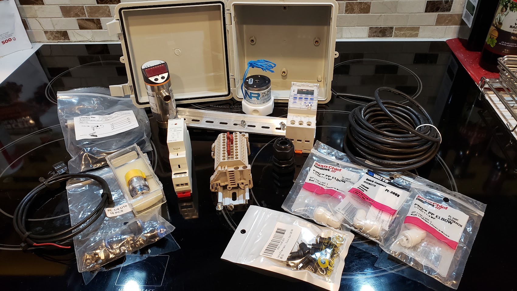
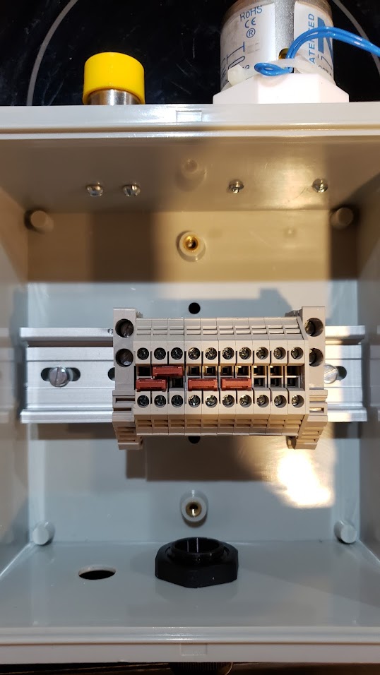
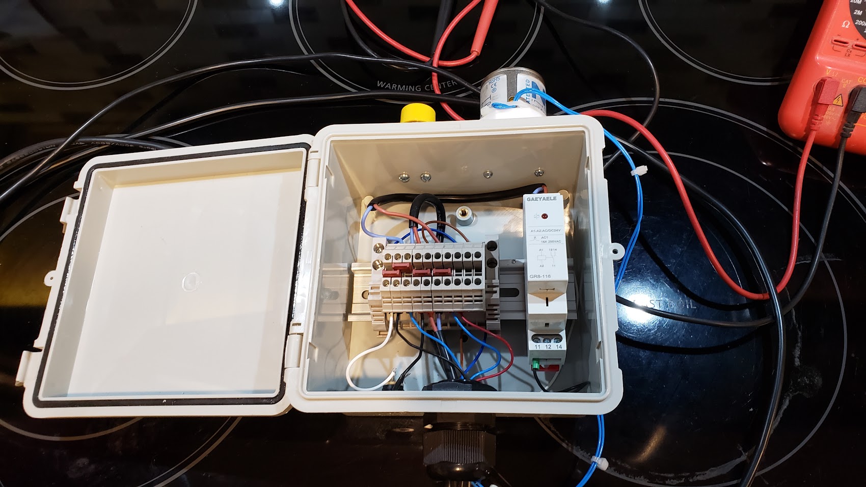
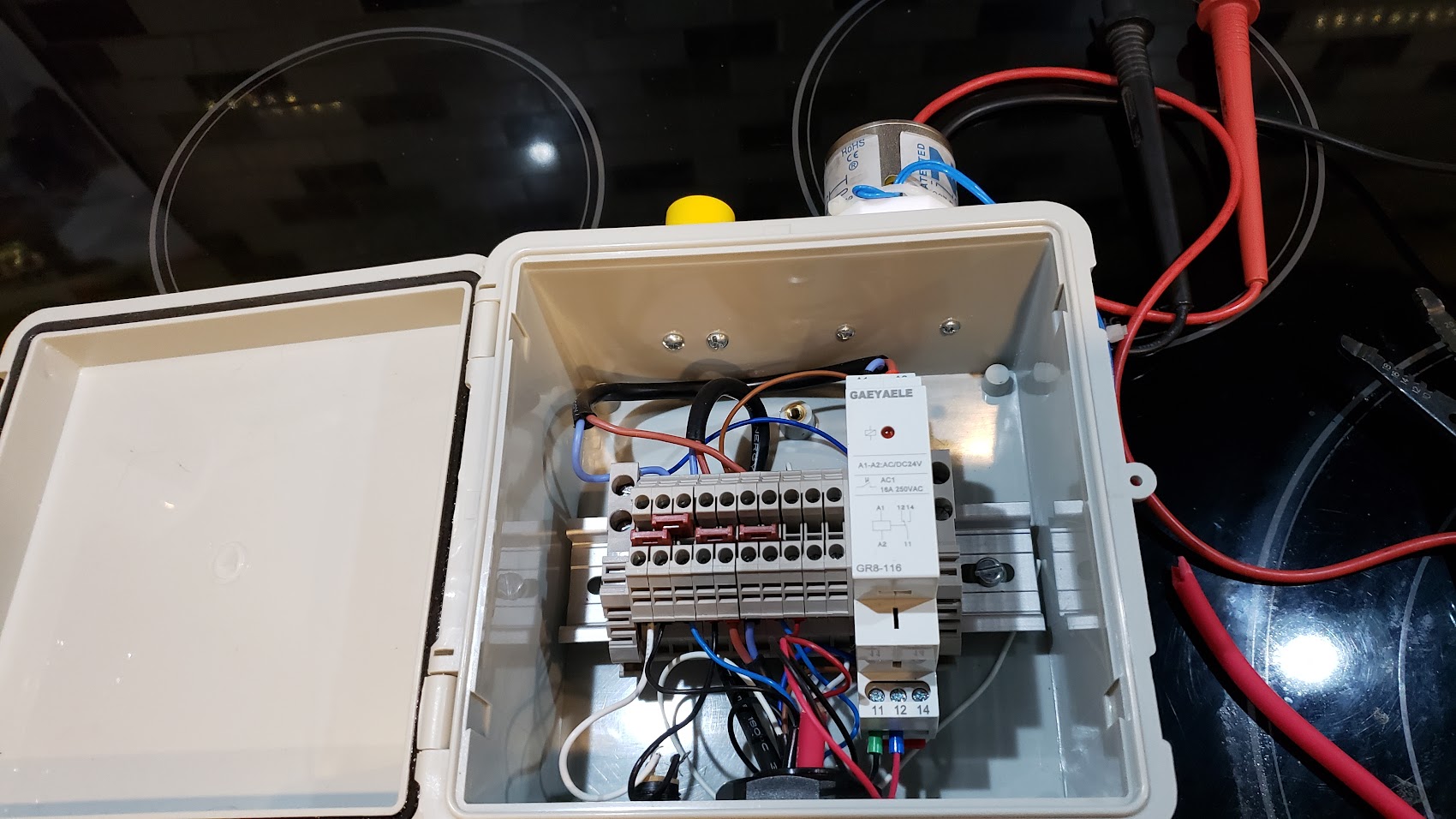
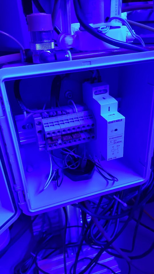
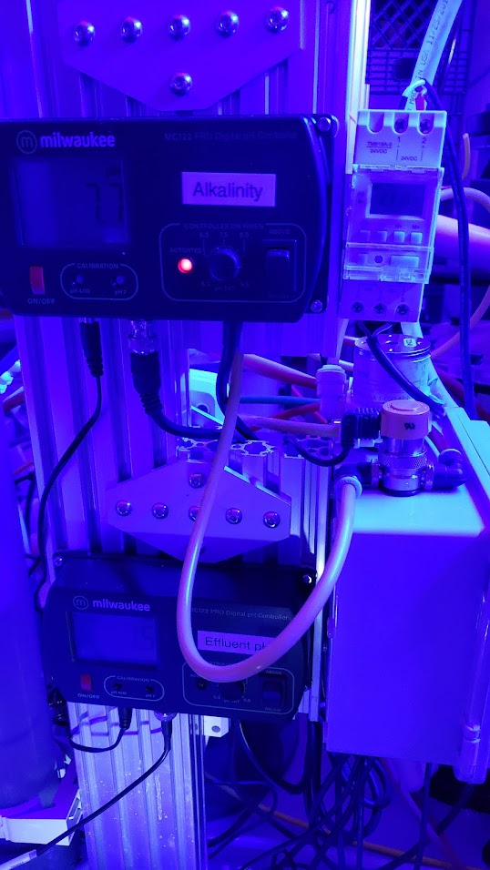
I disabled the CO2 using the switch I included on my auto tank switcher, purged out the CO2 until water was flowing out and then enabled the CO2 and open my effluent drain valve to allow displaced effluent to escape without back feeding. That is when I noticed that no CO2 appeared to be collecting in the ACR. The venturi was pulling 100% water and no bubbles were flowing through the media. The pressure transducer on my ACR controller was reading 7 PSI, which is a typical reading. I had the CO2 regulator set to 8 PSI, and the Clippard valve would always close before it ever reached 8 PSI in the past. To that point, after recently becoming aware of some ACR failures caused by over pressuring the reactor, I re-wired my controller to use the pressure transducer to keep the internal ACR pressure at or below 8 PSI by powering the Clippard valve from the programmable output on the transducer.
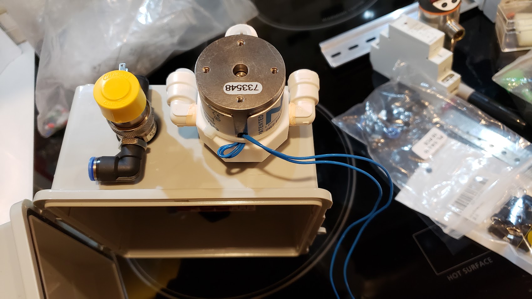
After not being able to get CO2 to flow, I relented and closed the feed pump ball valve and kept the effluent drain open. This allowed CO2 to start re-filling the gas pocket. As soon as I opened the feed pump ball valve, the CO2 re-filling halted again. What this showed me was that the Sicce pump I am tapping for the ACR feed, must have a head pressure of 7 PSI and was preventing the CO2 from pushing out effluent when the CO2 pressure was reading 7 PSI. The bypass valve on the feed for overriding the check valve was of no help in this case. Only closing the feed off entirely worked.
Then I increased my CO2 regulator to 10 PSI. The pressure transducer on my controller would climb to 8 PSI and then the over pressure protection would kick in and disable the valve. This allowed CO2 to again start to re-build the gas pocket even with the feed pump valve open and the effluent drain closed. This pattern continued of the valve being pulsed on briefly and then getting disabled, allowing CO2 to be added in tiny pulses.
After thinking about the new behaviour, I realized I no longer require the check valve bypass as the transducer is able to limit the overshoot above the feed pump head pressure. On the next purge I plan to see if the gas pocket can be rebuilt without using the effluent drain. It would take a few hours, but I am guessing it would work fine to slowly add CO2 as effluent is removed by my Masterflex pump.
I am the only person running this exact arrangement, Clippard valve with IFM pressure transducer, but nonetheless the results are quite cool.
Dennis
I disabled the CO2 using the switch I included on my auto tank switcher, purged out the CO2 until water was flowing out and then enabled the CO2 and open my effluent drain valve to allow displaced effluent to escape without back feeding. That is when I noticed that no CO2 appeared to be collecting in the ACR. The venturi was pulling 100% water and no bubbles were flowing through the media. The pressure transducer on my ACR controller was reading 7 PSI, which is a typical reading. I had the CO2 regulator set to 8 PSI, and the Clippard valve would always close before it ever reached 8 PSI in the past. To that point, after recently becoming aware of some ACR failures caused by over pressuring the reactor, I re-wired my controller to use the pressure transducer to keep the internal ACR pressure at or below 8 PSI by powering the Clippard valve from the programmable output on the transducer.
After not being able to get CO2 to flow, I relented and closed the feed pump ball valve and kept the effluent drain open. This allowed CO2 to start re-filling the gas pocket. As soon as I opened the feed pump ball valve, the CO2 re-filling halted again. What this showed me was that the Sicce pump I am tapping for the ACR feed, must have a head pressure of 7 PSI and was preventing the CO2 from pushing out effluent when the CO2 pressure was reading 7 PSI. The bypass valve on the feed for overriding the check valve was of no help in this case. Only closing the feed off entirely worked.
Then I increased my CO2 regulator to 10 PSI. The pressure transducer on my controller would climb to 8 PSI and then the over pressure protection would kick in and disable the valve. This allowed CO2 to again start to re-build the gas pocket even with the feed pump valve open and the effluent drain closed. This pattern continued of the valve being pulsed on briefly and then getting disabled, allowing CO2 to be added in tiny pulses.
After thinking about the new behaviour, I realized I no longer require the check valve bypass as the transducer is able to limit the overshoot above the feed pump head pressure. On the next purge I plan to see if the gas pocket can be rebuilt without using the effluent drain. It would take a few hours, but I am guessing it would work fine to slowly add CO2 as effluent is removed by my Masterflex pump.
I am the only person running this exact arrangement, Clippard valve with IFM pressure transducer, but nonetheless the results are quite cool.
Dennis