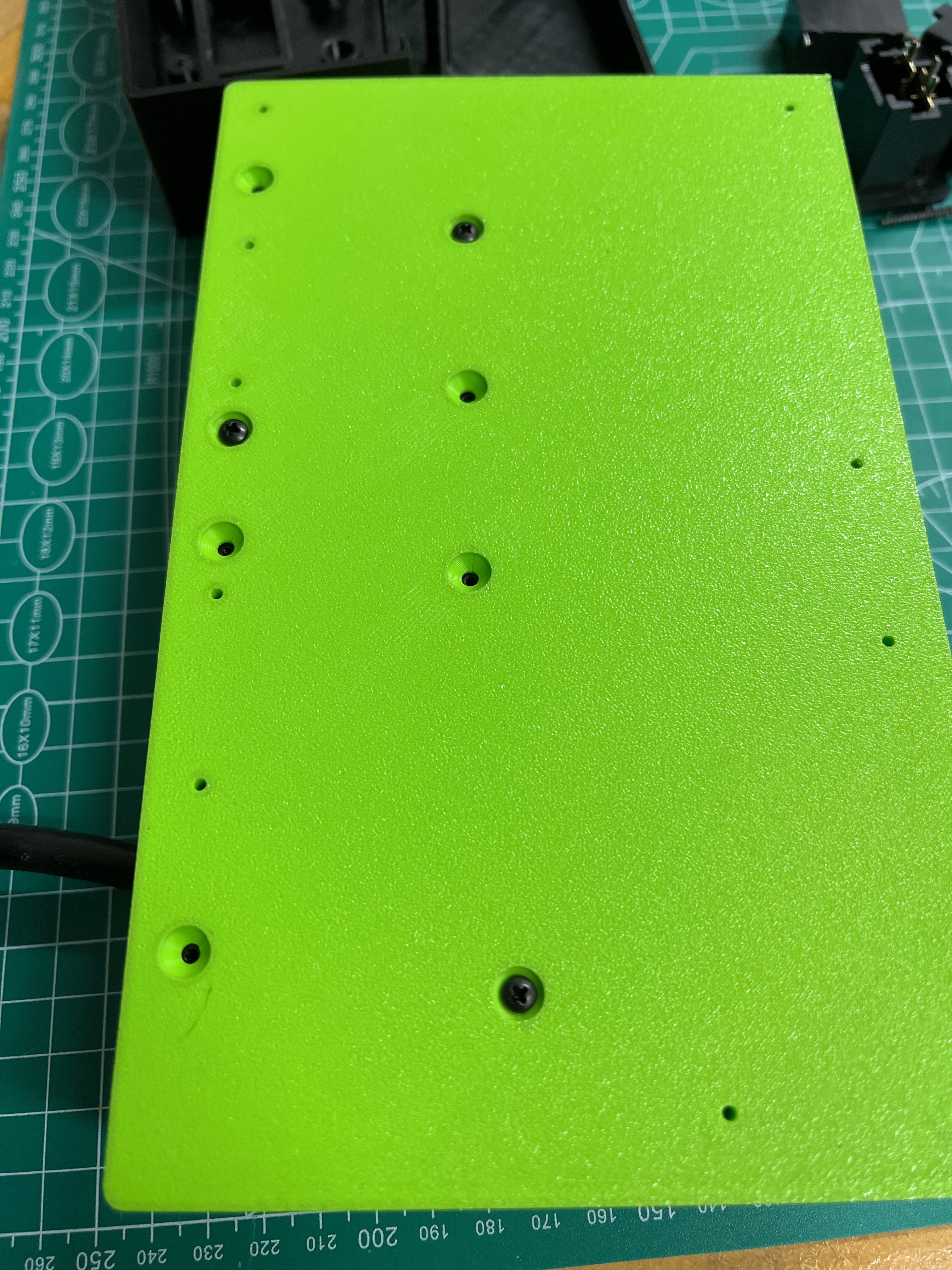
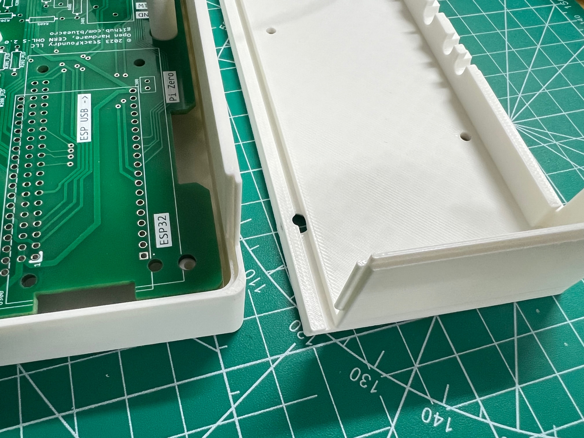
Nvm, got it. It didn't transfer the mounting holes in the pcb, but that's easy to transfer from the dxf file.


Follow along with the video below to see how to install our site as a web app on your home screen.
Note: This feature may not be available in some browsers.


How do I download the rv_pwr_es.x_t file?
Honestly, I don't even know how I downloaded the dwg file... it's not intuitive for the way my brain is wired... for sure
 github.com

Super weird it didn’t transfer slots or holes. I can try an export out of Inventor for the whole assembly. If I still had a SolidWorks seat I’d offer that but sadly I don’t.Nvm, got it. It didn't transfer the mounting holes in the pcb, but that's easy to transfer from the dxf file.


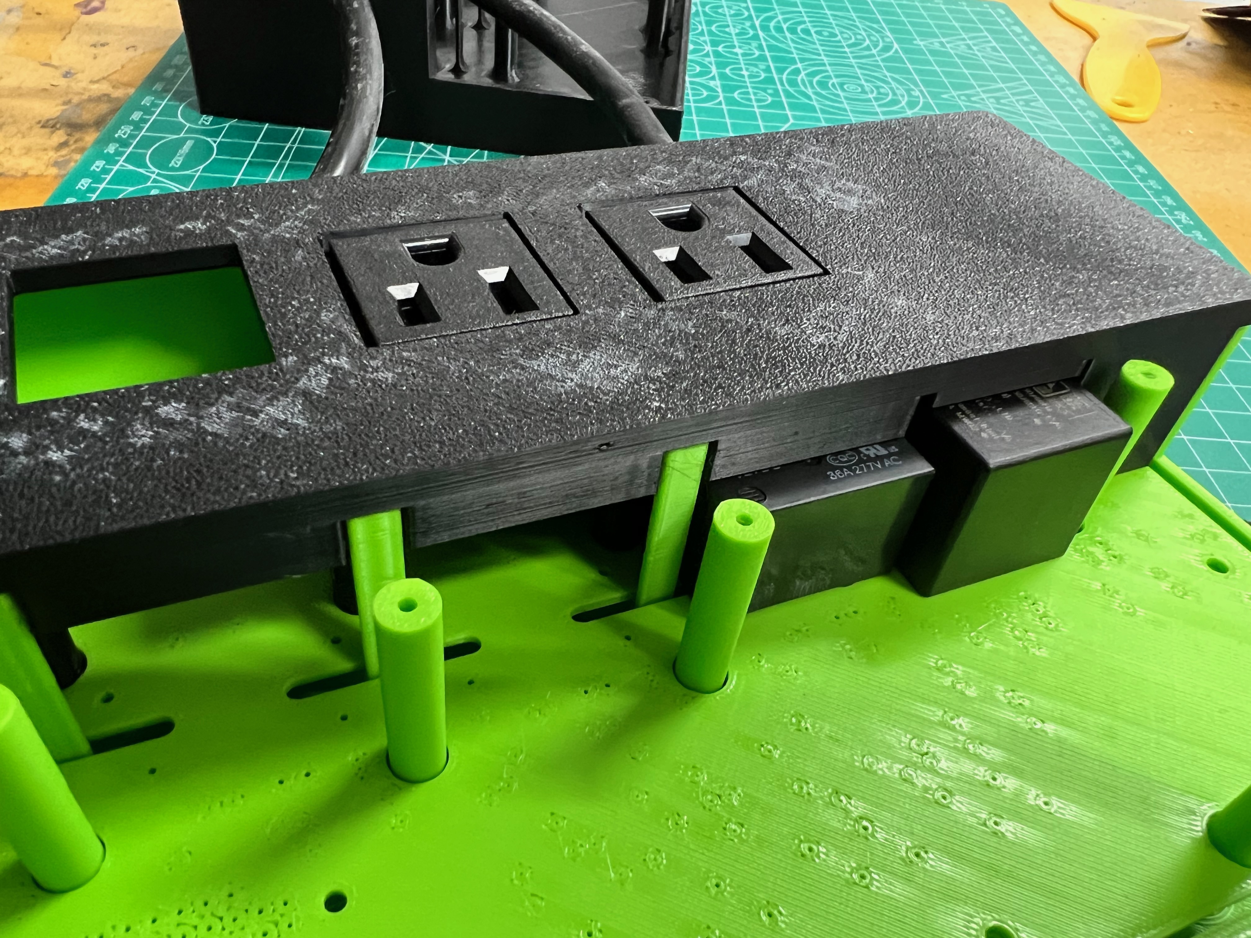
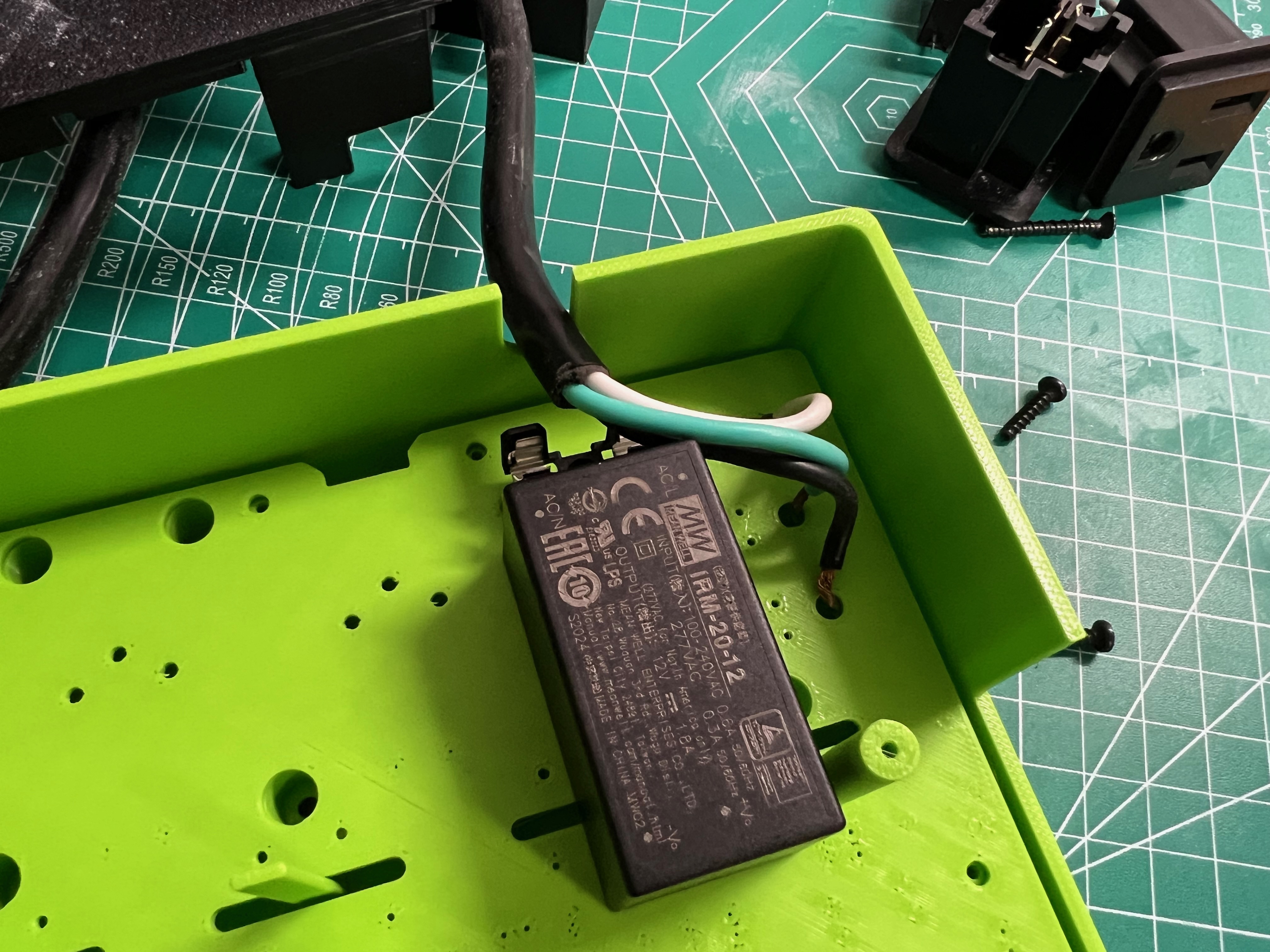
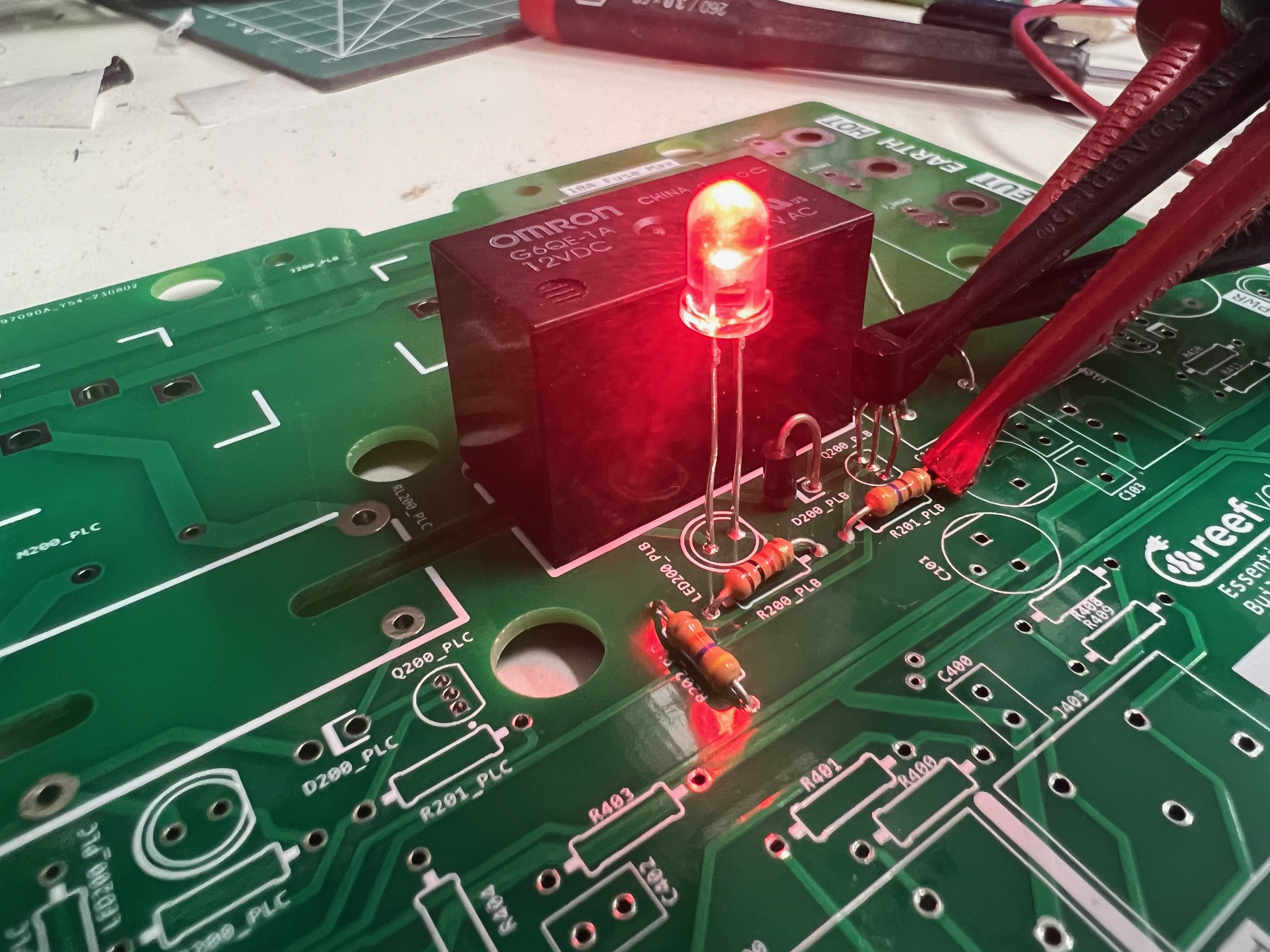
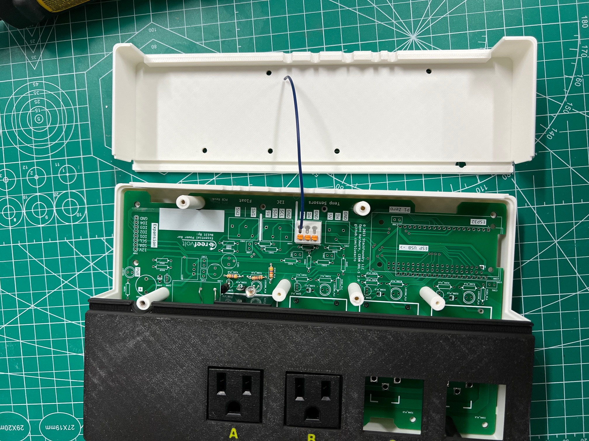

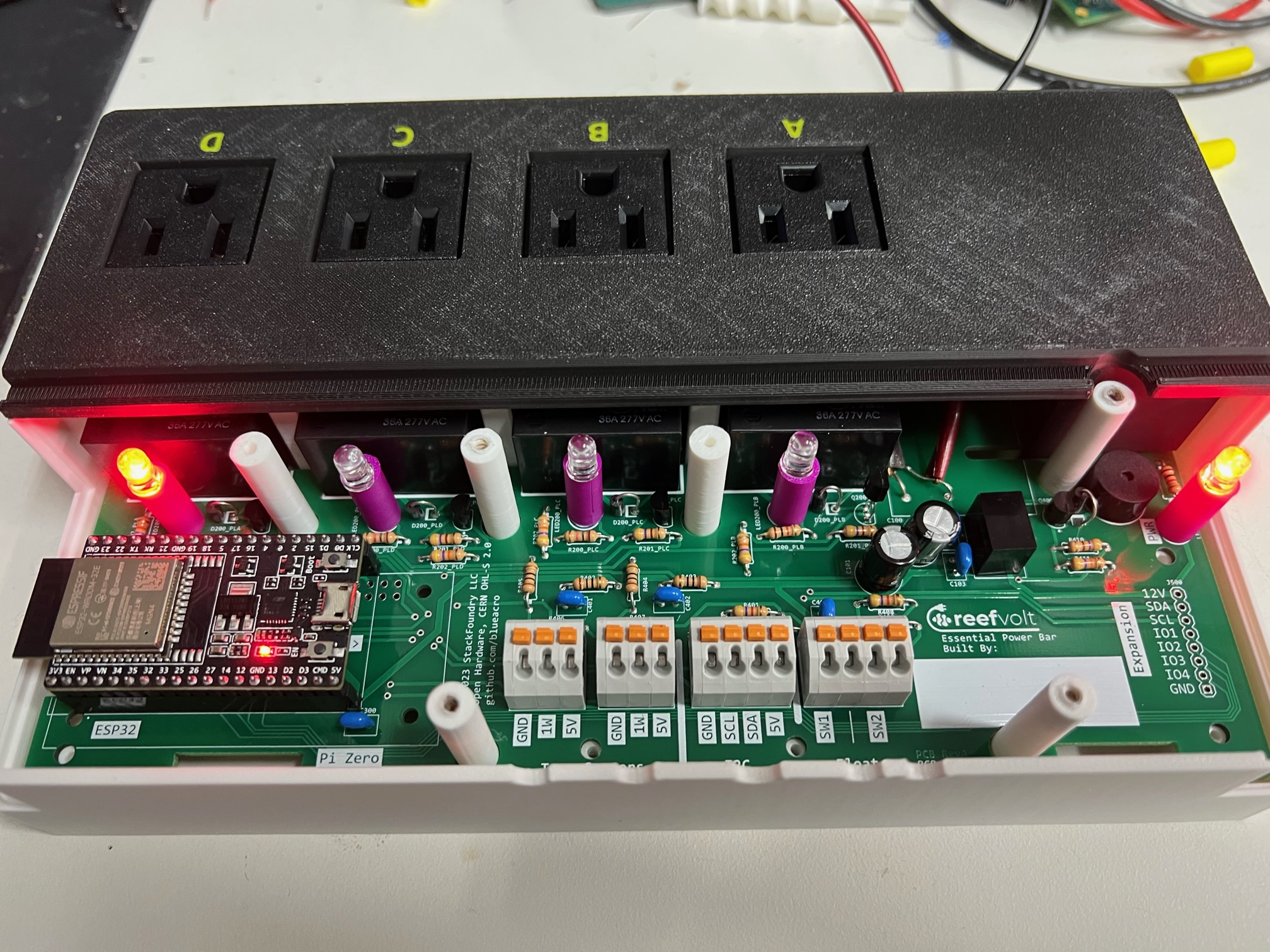
Did a quick build of one relay channel just to check the part suitability. Of course, the first one I built, the diode ended up backwards, and then I melted the switch transistor by dumping an amp through the poor 2n4401.
Not used to needing a solder sucker gun because I don't do much through hole parts, but was easy enough to swap.
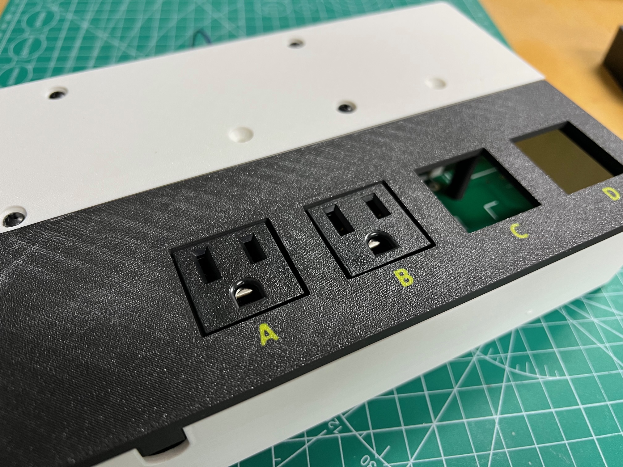
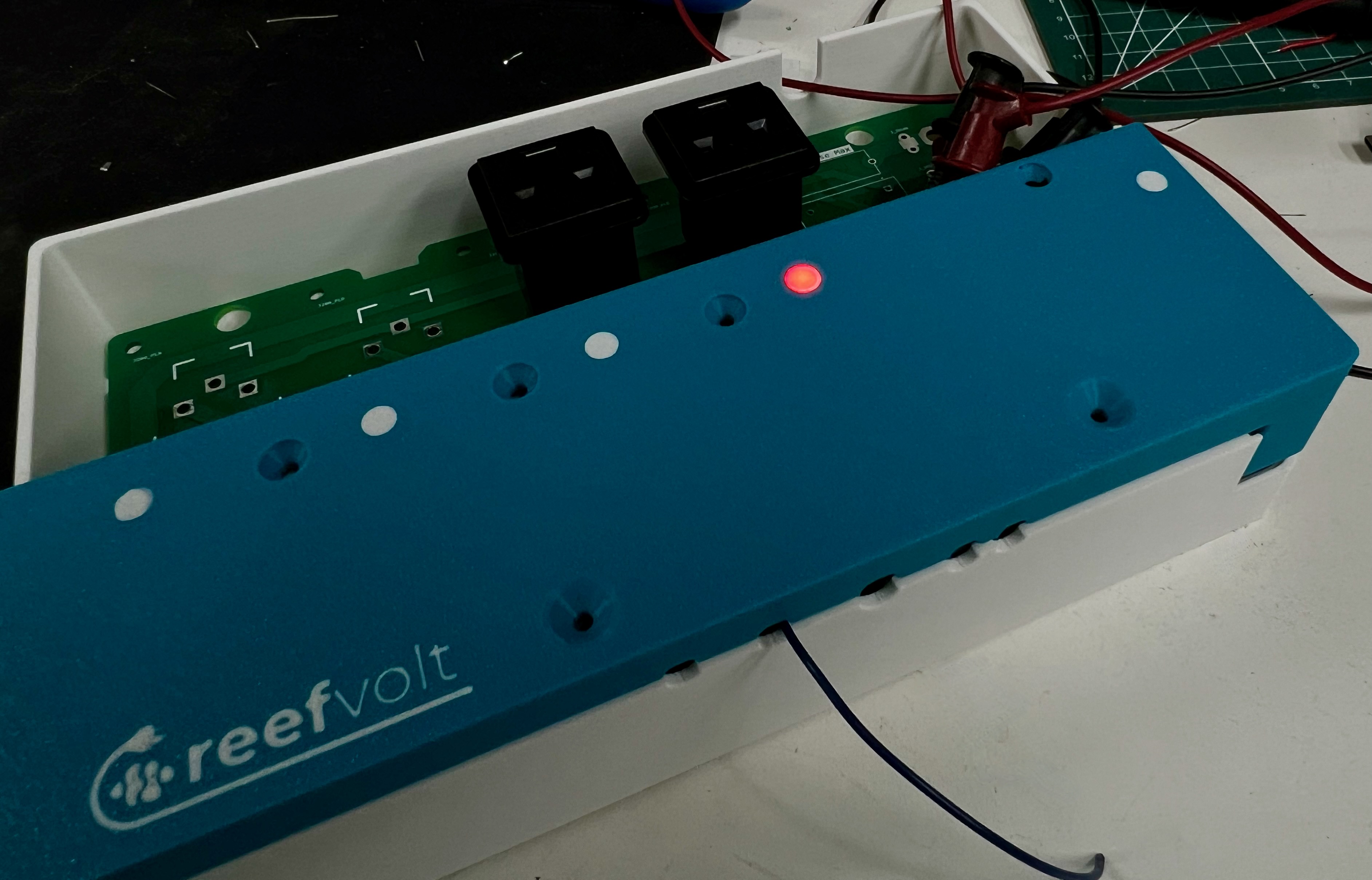
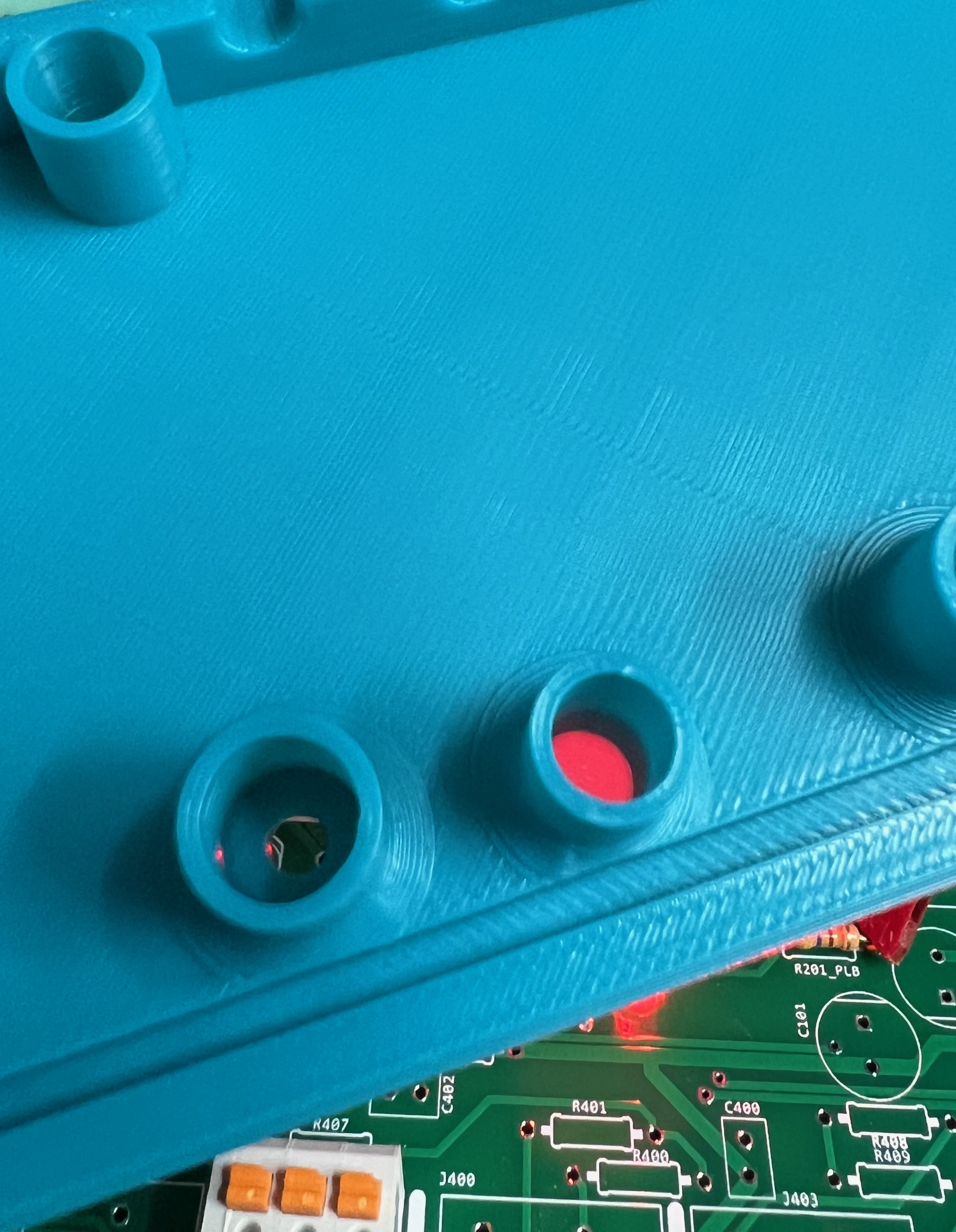
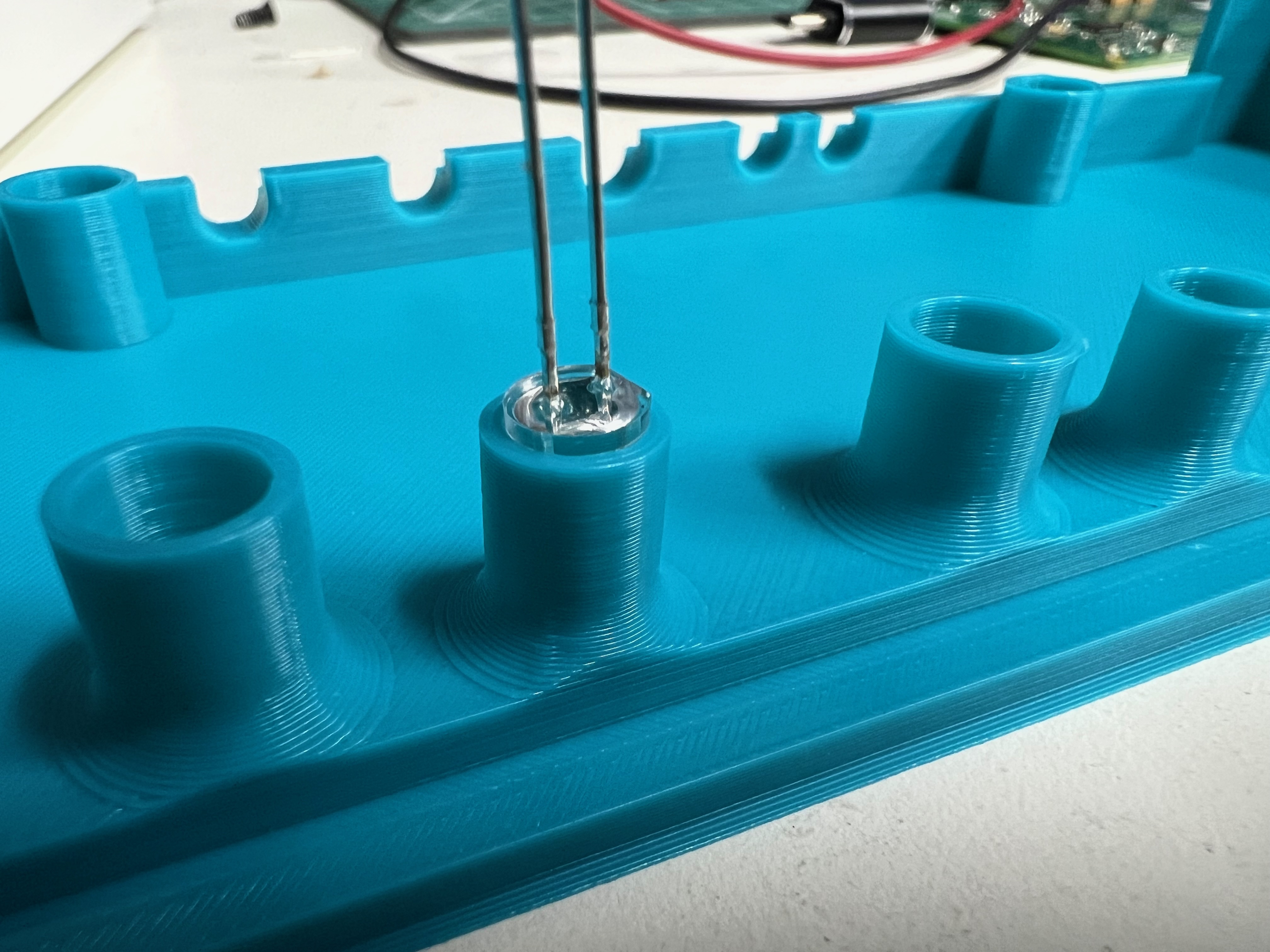
First off, the on LED is bright. I may reduce the current to it further.
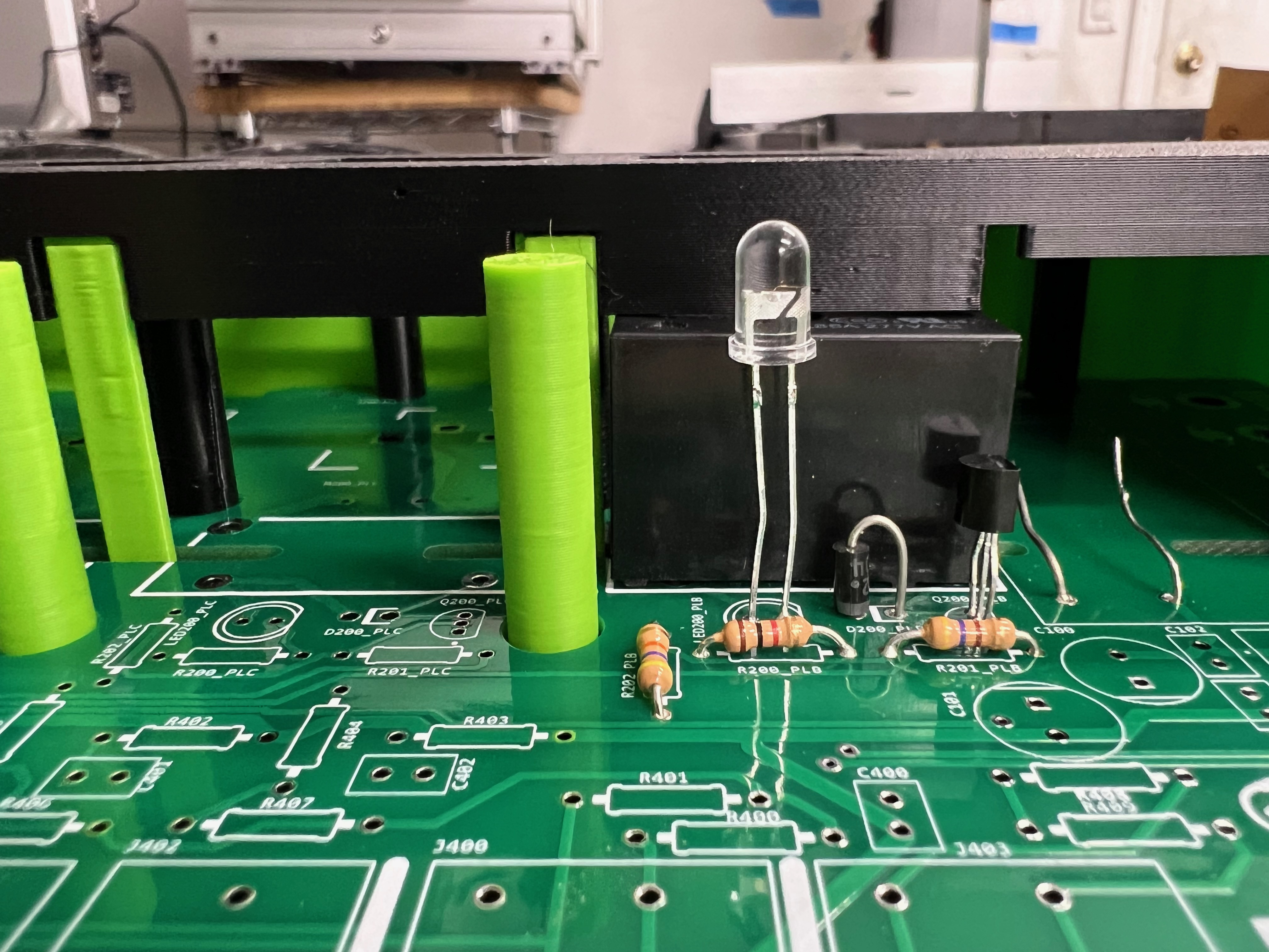
The other good news is an average LED legs seem juuust long enough to go to the top case. While I don't want too many holes in the case, it would be nice if the on LEDs were visible. Need to think on this one (maybe some snap in thin white plastic over the LED? Translucent PETG?)
Tertiary note is the relay is loud - its chonky inside and isn't a soft click. Don't use this for a wavemaker and old school pumps.
This looks great... if it had pH and Orb, it might be all I need for my IM 50 build... Any particular choice in mechanical vs SS for relays?

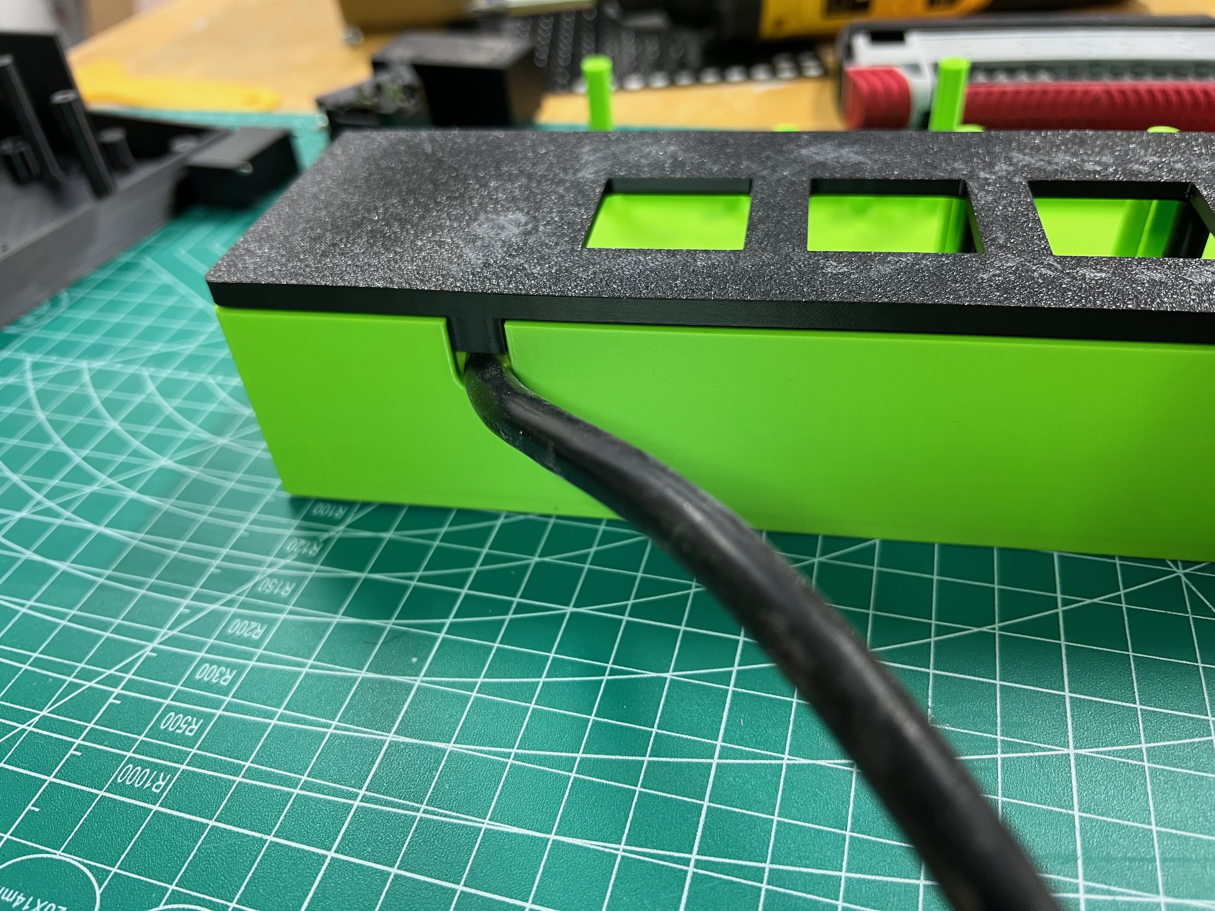
Looks awesome! I have been following your work for a while now on your blue acro site, very well thought out pcb designs and projects! Did you figure out your ac cable mount? If it helps, on my projects i have used a clamp style printed mount. Make a slightly oversize half circle base with threaded holes to either side for the mount, and another saddle clamp half circle that screws into the mount. Add 2 rows of raised hemispherical bosses circumscribing the inside of the mount and saddle that protrude ~.8mm to add a little grip and prevent cord pull out. Those style mounts have worked awesome for me in the past and are pretty secure. If you want i can screen-shot the cad drawing tomorrow if youd like.
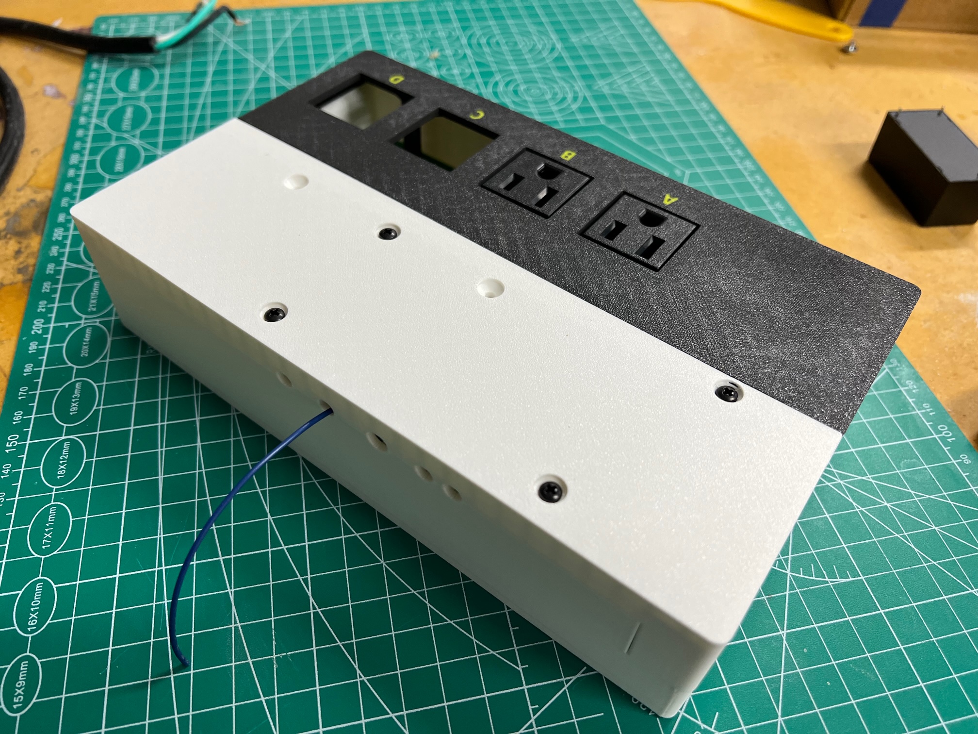
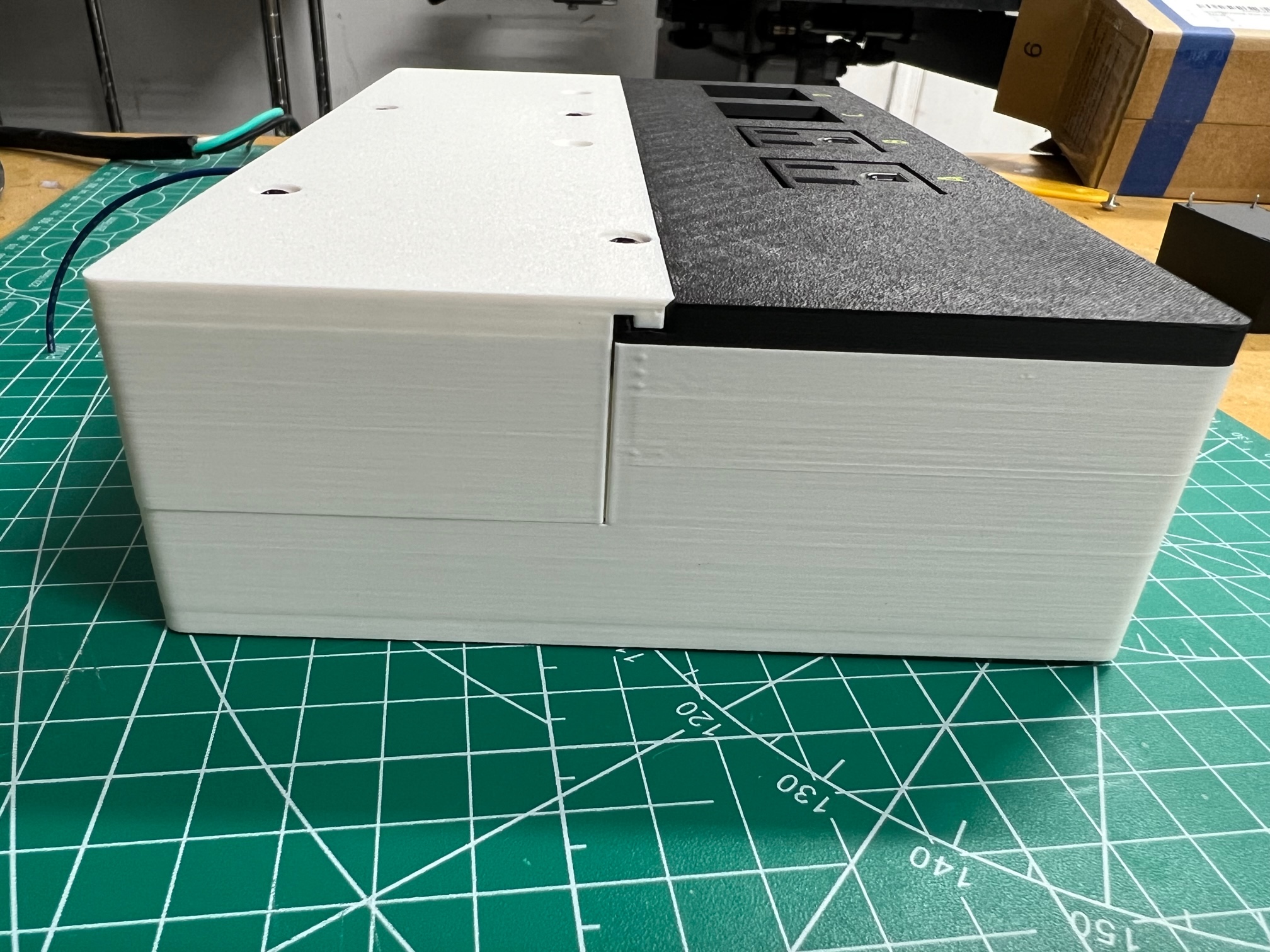
Snap in grips would definitely work, i just get lazy sometimes and don't want to have to hunt one down lol. I had room in this case to make them all internal tooI hadn’t yet spent time there and actually didn’t even think of using a print in saddle clamp. Great idea - there is room to make one externally.
I had thought of using snap on cord grips which then slide into a slot in the case (something like a gromet you’d find for a metal case), but the variability of power cords makes that a tough option. Screw down saddle clamp is much for versatile.

Snap in grips would definitely work, i just get lazy sometimes and don't want to have to hunt one down lol. I had room in this case to make them all internal too
Here is a few screen-shots of one of mine, this one is actually for 2 cords, one is a rectangular AC cord, like for a power supply, the other for a 3 wire round extension cord.