

===
Essential Links:
GitHub repo: https://github.com/blueacro/reefvolt-essential-power-bar/
Build guide: https://blueacro.github.io/reefvolt-essential-power-bar/ (Coming Soon)
===
Hi! You may remember me from some other past projects around here (often complicated, supply constrained and pandemic delayed, possibly forever). One thing I needed for a personal aquarium build was a pretty simple power bar for controlling heaters, chillers, and hosting a few simple sensors for the above. I figured, why not make a very simple design, as a single PCB, using nothing but simple through hole parts, as a build-it-yourself design? And then just share it?
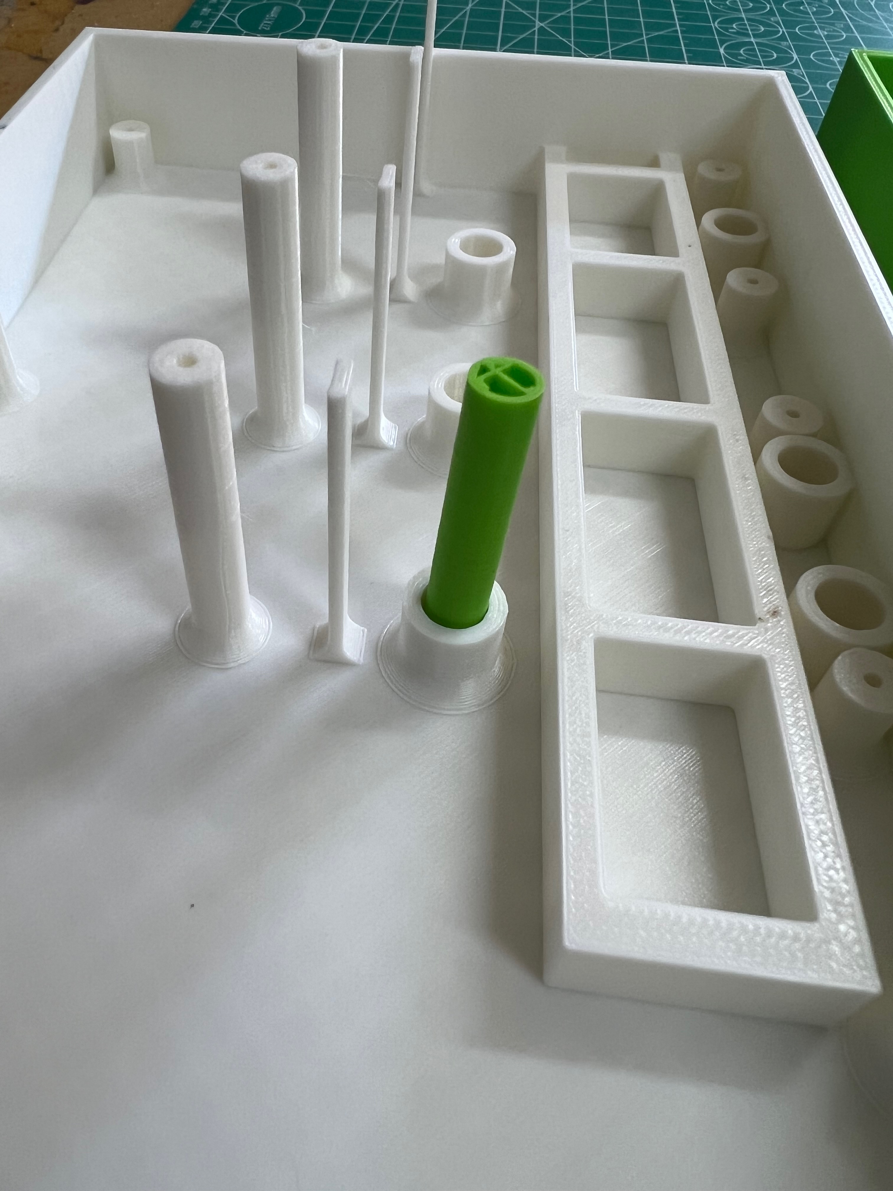
This project is designed to not have me as the critical path to building it - you can order the parts from the usual electronics distributors, print (or get printed) the case, and order the PCB from the PCB supplier of your choice from the uploaded Gerber files. Realistically, you should be able to get this built for ~$100 USD, not counting time and the 3d printed case.
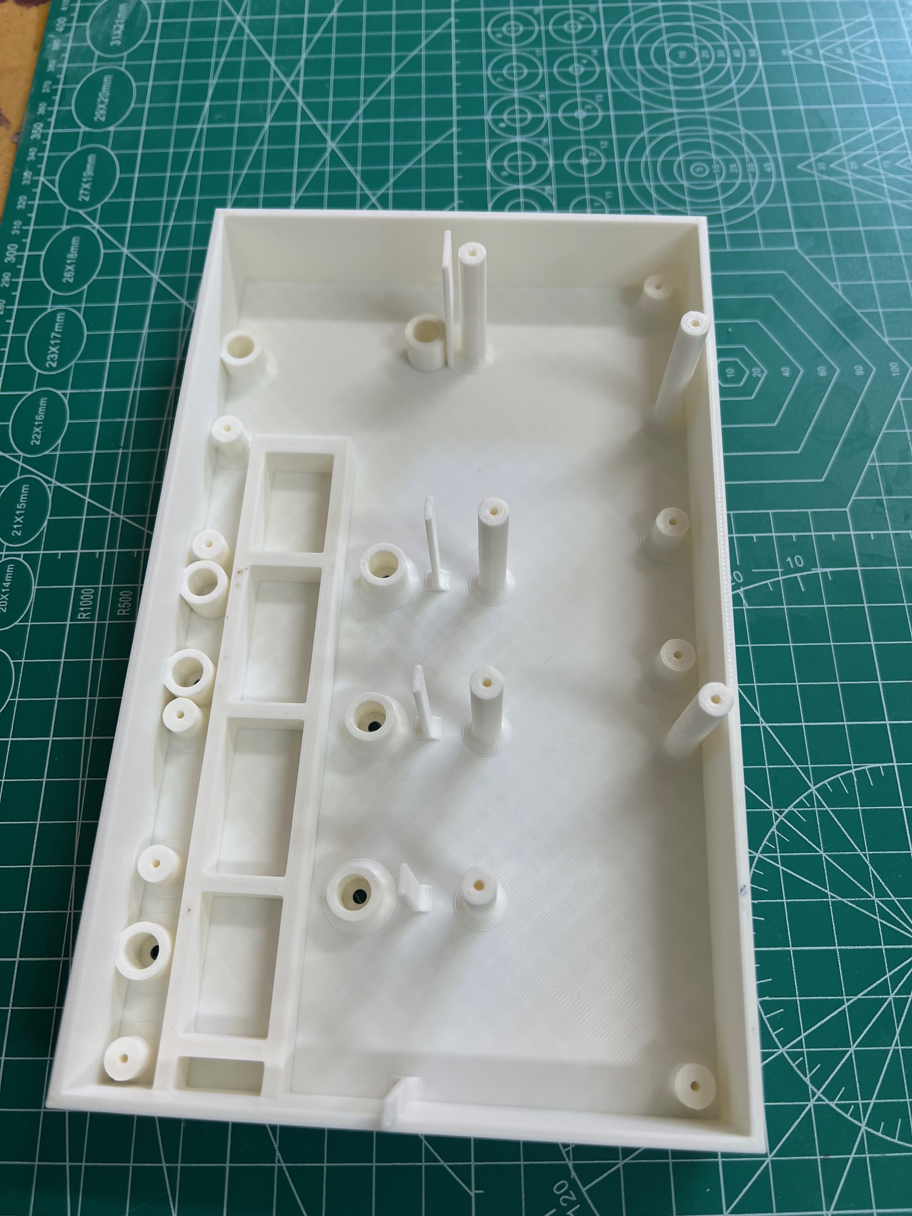
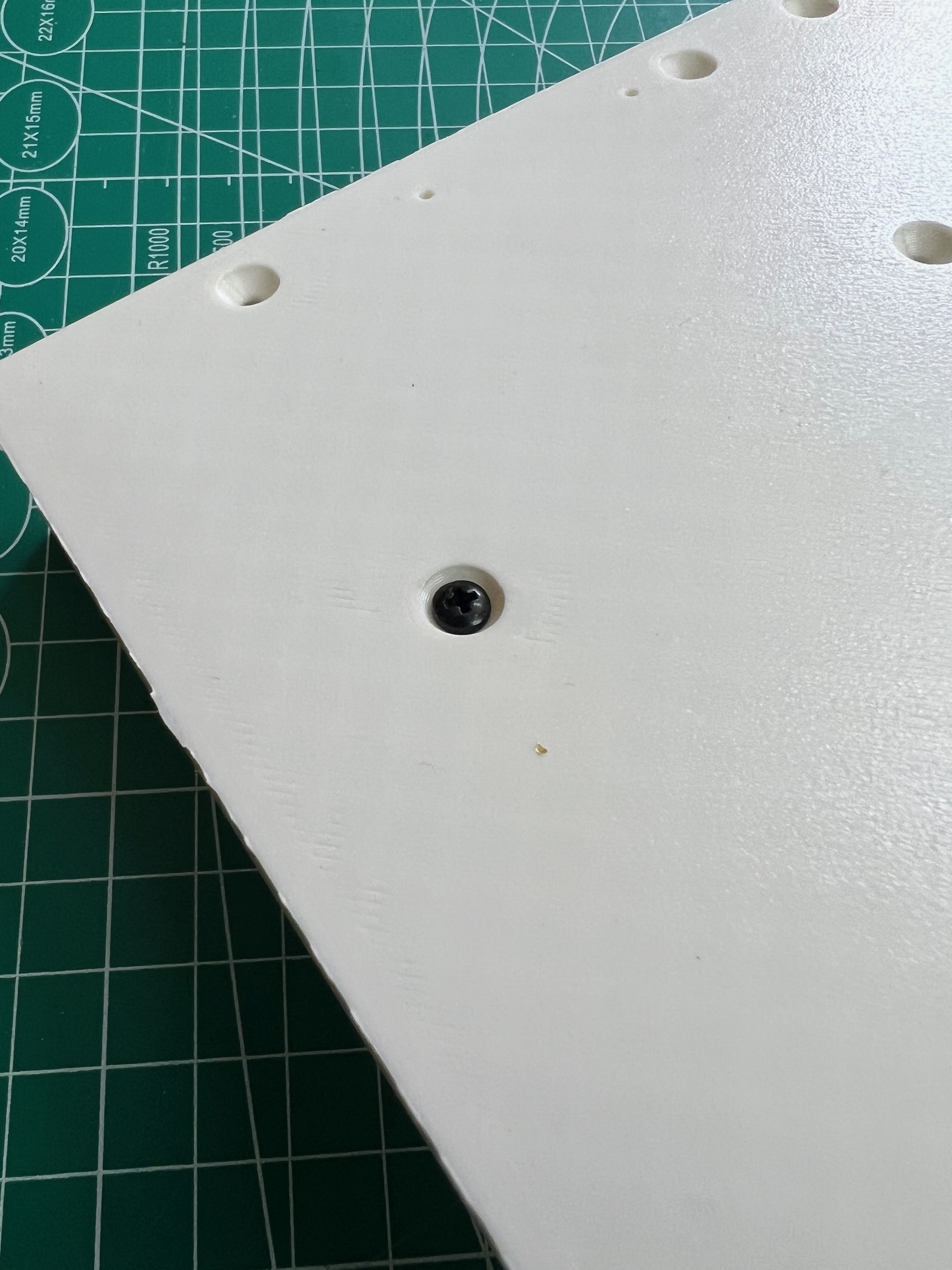
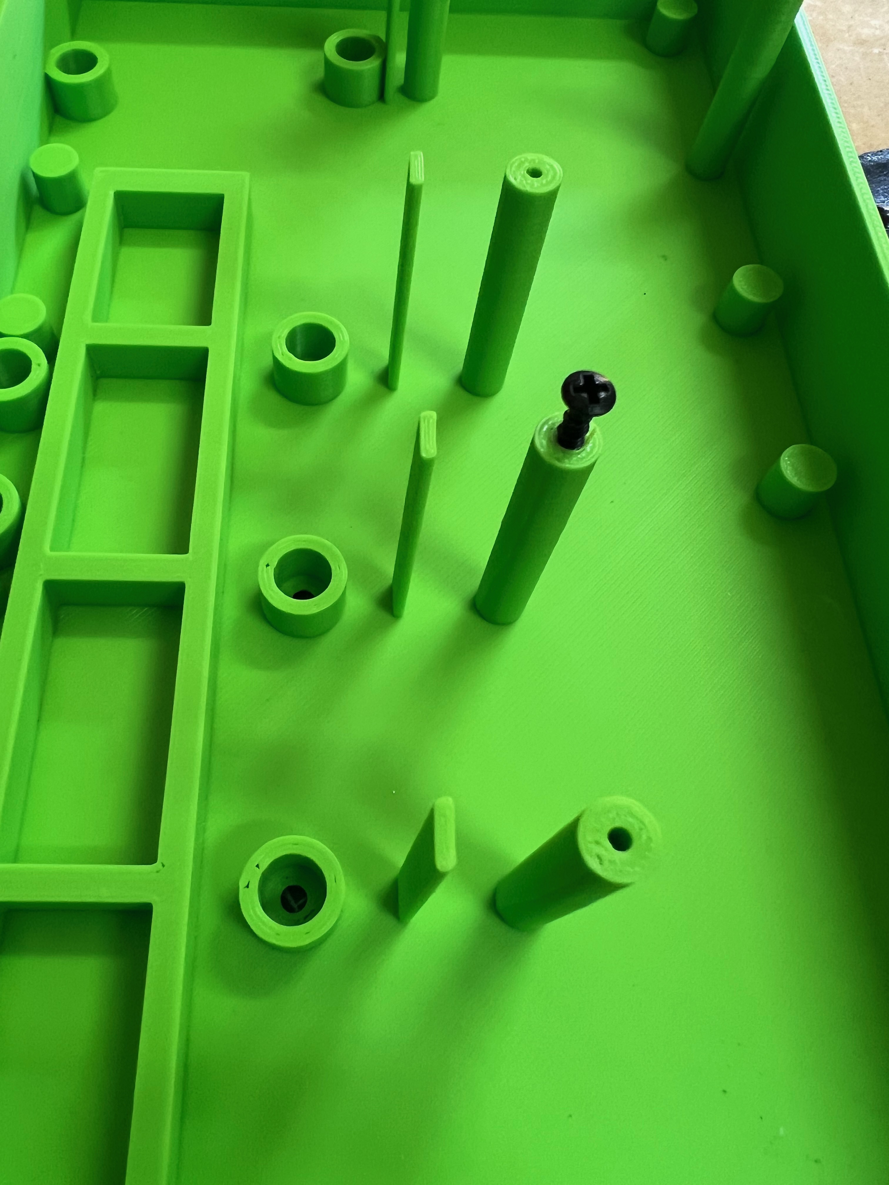
For the first post, I will caution I haven't built this yet, so some changes will inevitably crop up. Documentation will be updated as needed. Including pictures in this first post.
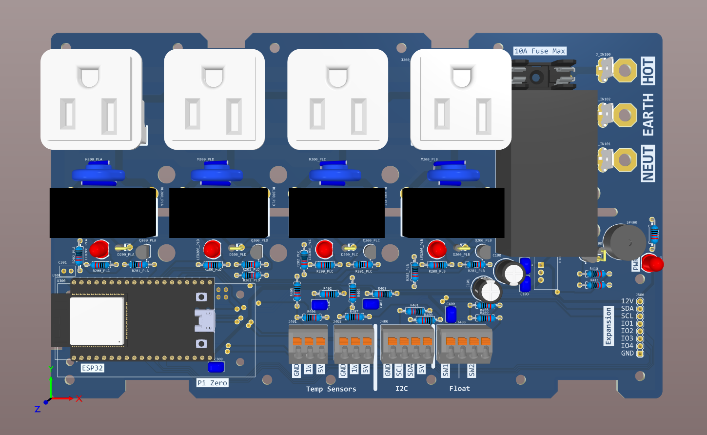
A quick look at the concept:
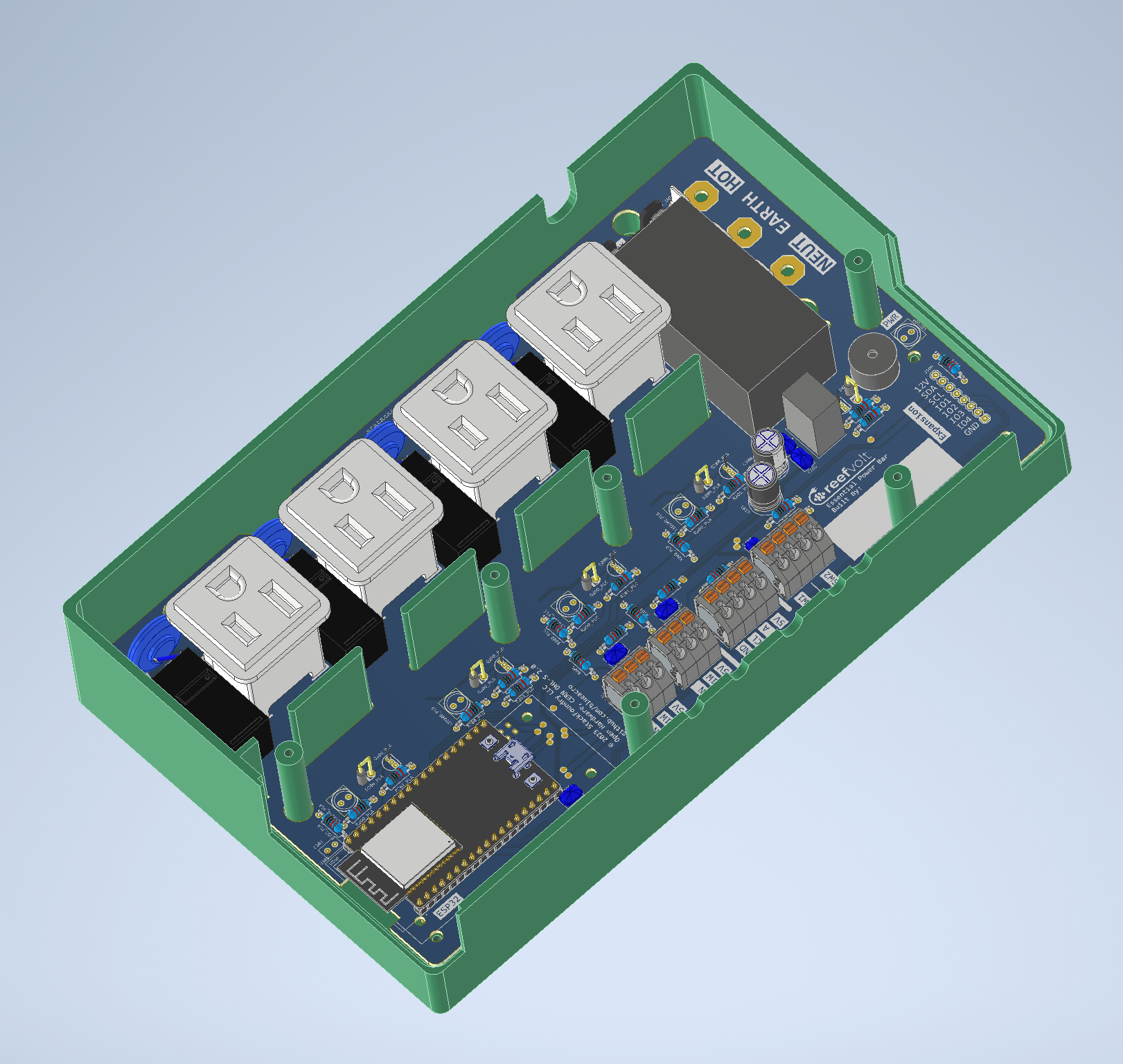
Basic specs:
- 4 outlets (designed for North America, sorry, but maybe can be spun with other connectors)
- 4 heavy-duty relays switching it (Omron G5RL series, 16A rated), with MOV snubbers on the AC side of the relay
- On-board fuse
- On board 12V 20W power supply (Meanwell IRM-20-12)
- On board 5V 5W DC/DC converter (CUI module)
- Mounting positions for either an ESP32 board, or a Raspberry Pi Zero, depending on how you want to control it.
- An on-board loud buzzer for alarming
- On board quick terminal blocks for:
- 2 1Wire temperature sensor channels (for redundancy with failed sensors, second channel will require changes in ReefPi to work)
- I2C connection
- Two float switches or other simple on/off switches
- A header allowing an expansion board to be added
This board is designed for hand soldering assembly using nothing but a basic solder iron, and gives you everything you might need (the essentials), in one controller. Note that I don't intend to offer pre-built boards for this - this is a purely DIY project.
Essential Links:
GitHub repo: https://github.com/blueacro/reefvolt-essential-power-bar/
Build guide: https://blueacro.github.io/reefvolt-essential-power-bar/ (Coming Soon)
===
Hi! You may remember me from some other past projects around here (often complicated, supply constrained and pandemic delayed, possibly forever). One thing I needed for a personal aquarium build was a pretty simple power bar for controlling heaters, chillers, and hosting a few simple sensors for the above. I figured, why not make a very simple design, as a single PCB, using nothing but simple through hole parts, as a build-it-yourself design? And then just share it?
This project is designed to not have me as the critical path to building it - you can order the parts from the usual electronics distributors, print (or get printed) the case, and order the PCB from the PCB supplier of your choice from the uploaded Gerber files. Realistically, you should be able to get this built for ~$100 USD, not counting time and the 3d printed case.
For the first post, I will caution I haven't built this yet, so some changes will inevitably crop up. Documentation will be updated as needed. Including pictures in this first post.
A quick look at the concept:
Basic specs:
- 4 outlets (designed for North America, sorry, but maybe can be spun with other connectors)
- 4 heavy-duty relays switching it (Omron G5RL series, 16A rated), with MOV snubbers on the AC side of the relay
- On-board fuse
- On board 12V 20W power supply (Meanwell IRM-20-12)
- On board 5V 5W DC/DC converter (CUI module)
- Mounting positions for either an ESP32 board, or a Raspberry Pi Zero, depending on how you want to control it.
- An on-board loud buzzer for alarming
- On board quick terminal blocks for:
- 2 1Wire temperature sensor channels (for redundancy with failed sensors, second channel will require changes in ReefPi to work)
- I2C connection
- Two float switches or other simple on/off switches
- A header allowing an expansion board to be added
This board is designed for hand soldering assembly using nothing but a basic solder iron, and gives you everything you might need (the essentials), in one controller. Note that I don't intend to offer pre-built boards for this - this is a purely DIY project.
Last edited:


") .
.