GHL flow sensor flow rates

Users Who Are Viewing This Thread (Total: 1, Members: 0, Guests: 1)

foxt

Valuable Member
View Badges
Joined
Apr 6, 2016
Messages
1,633
Reaction score
2,363
Rating - 0%
0   0   0
I have asked this over on GHL's forums, but no response so thought I would try it on R2R ... with the availability of Apex' FMM, perhaps there will be more interest in GHL's flow sensors, and this question may be helpful for others.

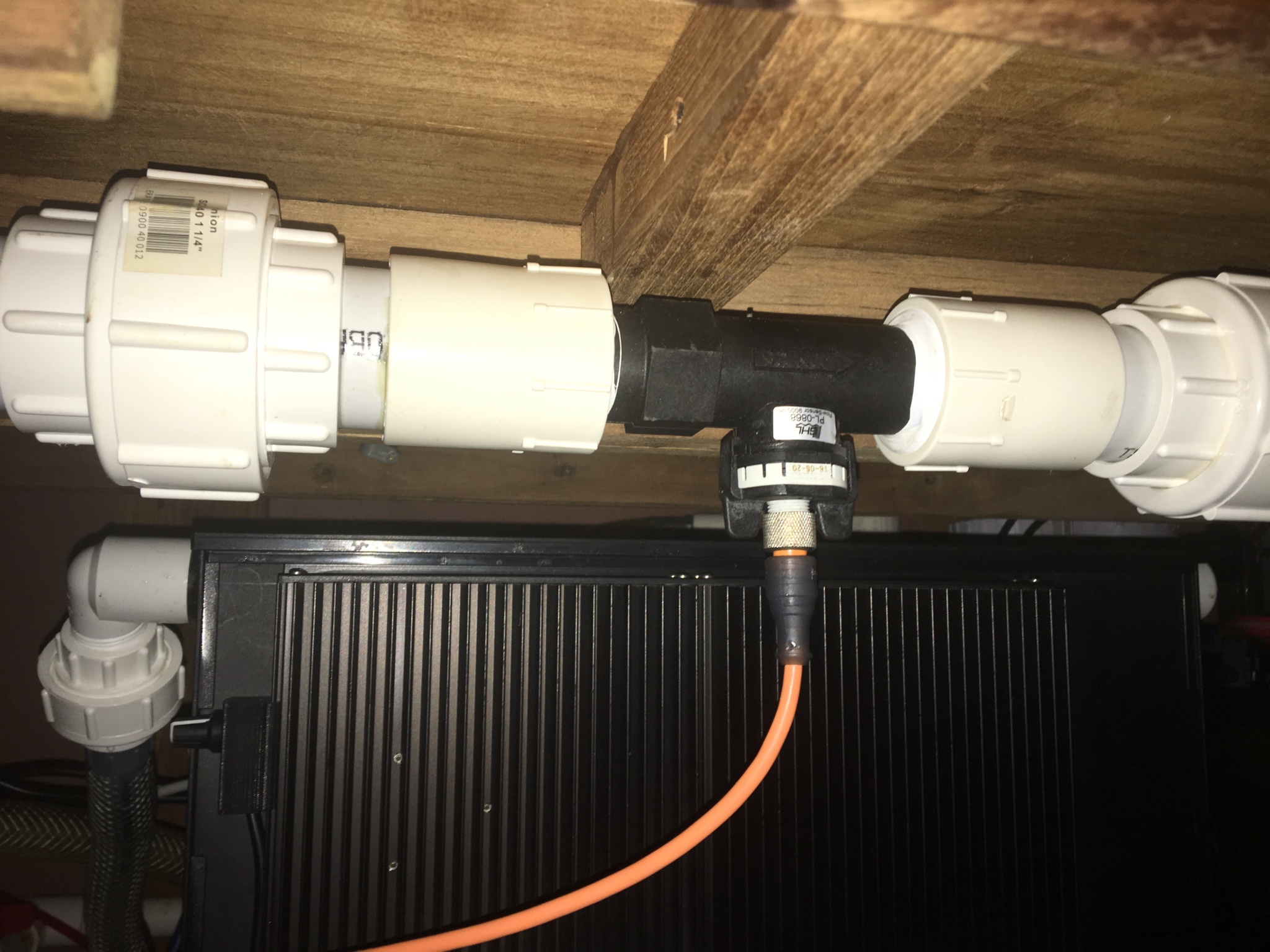
I purchased a 9000 l/h sensor, thinking that I can plumb this into my return line. My return line is 1-1/2", which splits into two 1" returns at the tank (one on both sides). Since the flow sensor has an internal diameter of about 1", and threaded fittings that are 1-1/4" BSPP, I thought I would be able to plumb the flow sensor directly to my 1" lines. This is not the case: there does not seem to be a way to connect the BSPP threads in that size to 1" PVC in the US. The only solution for making this connection appears to be to use half of a 25MM union, which will step down the 1" internal diameter of the sensor to 3/4" PVC.

I am flowing about 1000-1200 gph (call it 4000 l/h) through this 1" pipe. If I step this down to 3/4", I am concerned that I will be adding a lot more head to my return line. This has me considering a bypass configuration. Alternatively, I could connect the 25mm union to the 3/4" pvc and then step that right up to 1" pvc, but that 3/4" restriction will still be in the line.

Which brings me to my question - in the US, what is the actual max flow for this sensor that people are achieving? Since our only option here is to use 3/4" pipe, and since that size pipe has a max flow rate (at 12 f/s) of something like 1400 gph (5000 l/h), the math would say that this sensor can not achieve 9000 l/h. But, that is the theoretical picture - what do people see in the real world?
 
OP
OP
foxt

foxt

Valuable Member
View Badges
Joined
Apr 6, 2016
Messages
1,633
Reaction score
2,363
Rating - 0%
0   0   0
Thanks! What max flow rate are you able to achieve through the 9000 l/h setup in your picture? And do you have any ideas as to what kind of head the restriction through the sensor added to your return line? I am planning on pushing 2000 gph through 1.5" PVC from my basement to the DT upstairs, about 16' of head without the flow sensor in the line ...
 

Dumaurier7

Well-Known Member
View Badges
Joined
Dec 12, 2015
Messages
760
Reaction score
276
Location
Carribean
Rating - 0%
0   0   0
I am seeing 3000+ l/h at 98w on my 150w RD3 with another 1100 going to my manifold which seems about right .
 

d2mini

5000 Club Member
View Badges
Joined
Sep 2, 2013
Messages
5,059
Reaction score
8,549
Location
Houston, TX
Rating - 0%
0   0   0
I'm attempting to upsize mine from the 3/4 fittings to 1.25" fittings.
Ordered these on ebay and they should be here any day.
http://www.ebay.com/itm/282069022278
BSPT fittings are easy to find. But BSPP fittings are a BEAR to find!
These are supposed to be threaded on one side and slip on the other. BRS and Coralvue sell the slip to slip conversions.
 

d2mini

5000 Club Member
View Badges
Joined
Sep 2, 2013
Messages
5,059
Reaction score
8,549
Location
Houston, TX
Rating - 0%
0   0   0
BTW, if you are running 1.5" pipe to the flow meter and after the flow meter, your biggest restriction is the flow meter itself.
Pushing that water through the 3/4" fittings on either end, isn't adding (or I guess removing in this case) anything that substantial.
It's no where near like if you were running 3/4 pipe the whole way.
 

Dumaurier7

Well-Known Member
View Badges
Joined
Dec 12, 2015
Messages
760
Reaction score
276
Location
Carribean
Rating - 0%
0   0   0
be5d0c26ef27f4ef4ba1bd66874ec753.jpg


1.25" pipe and fittings.
 
OP
OP
foxt

foxt

Valuable Member
View Badges
Joined
Apr 6, 2016
Messages
1,633
Reaction score
2,363
Rating - 0%
0   0   0
BSPT fittings are easy to find. But BSPP fittings are a BEAR to find!
Been there, done that. Please keep us posted with what you try next, thanks! One question - you say that you are upsizing to 1-1/4"; were you using the 3/4" fittings with the sensor, and if so, any idea what max flow might have been?

Pushing that water through the 3/4" fittings on either end, isn't adding (or I guess removing in this case) anything that substantial.
This is where I get confused. The sensor itself has an ID of about 1". At moderate pressure, this should be able to flow the 9000l/h as advertised, but at an unknown head loss. When you slap the 3/4" bushings on both sides, that introduces an additional restriction which theoretically increases head loss, right?. True, there is only a very short distance that is restricted, and it is not nearly as much as a long run of 3/4" pipe, but it is something.

I was hoping someone with this already built would be able to tell us what effect they are seeing on high flow rates. Dumarier7's flow rates are about half of the rated capacity of the sensor, but I don't know if he is trying to push more than that. And he isn't using the 3/4" fittings, he has something larger set up.

Dumarier7's picture shows what looks like 1-1/4" female adapters screwed on to the sensor. I tried the standard 1-1/4" adapter, and the BSPT adapter (knows as G 1-1/4"), and neither of those worked. Clearly something is working for him in the picture, and he's going to let us know what those parts are in the next week or so.
 

d2mini

5000 Club Member
View Badges
Joined
Sep 2, 2013
Messages
5,059
Reaction score
8,549
Location
Houston, TX
Rating - 0%
0   0   0
This is where I get confused. The sensor itself has an ID of about 1". At moderate pressure, this should be able to flow the 9000l/h as advertised, but at an unknown head loss. When you slap the 3/4" bushings on both sides, that introduces an additional restriction which theoretically increases head loss, right?. True, there is only a very short distance that is restricted, and it is not nearly as much as a long run of 3/4" pipe, but it is something.

I was hoping someone with this already built would be able to tell us what effect they are seeing on high flow rates. Dumarier7's flow rates are about half of the rated capacity of the sensor, but I don't know if he is trying to push more than that. And he isn't using the 3/4" fittings, he has something larger set up.

Dumarier7's picture shows what looks like 1-1/4" female adapters screwed on to the sensor. I tried the standard 1-1/4" adapter, and the BSPT adapter (knows as G 1-1/4"), and neither of those worked. Clearly something is working for him in the picture, and he's going to let us know what those parts are in the next week or so.
Correct, it will take away some of your flow but it will be a pretty small amount. If we were setting up an office pool and I had to plunk down a few bucks, I'd guess you will lose 25 gph or less. ;)

I have another recent thread I started after I received mine and was able to confirm that I was only getting around 600 gph out of my L1 return pump. So i started making changes to my return plumbing.
Things you would think would have made a big diff only netted me like 25 gph.
I would like to see GHL come out with a 1.5" I.D. sensor, or even a 2". I'd much rather upsize at the flow sensor than downsize.
 
OP
OP
foxt

foxt

Valuable Member
View Badges
Joined
Apr 6, 2016
Messages
1,633
Reaction score
2,363
Rating - 0%
0   0   0
I would like to see GHL come out with a 1.5" I.D. sensor, or even a 2". I'd much rather upsize at the flow sensor than downsize.
Especially since Neptune/Apex has their 2" option.

I'll go find your other thread to see what you discovered re: flow restrictions ...
 

Creating a strong bulwark: Did you consider floor support for your reef tank?

  • I put a major focus on floor support.

    Votes: 54 40.3%
  • I put minimal focus on floor support.

    Votes: 28 20.9%
  • I put no focus on floor support.

    Votes: 48 35.8%
  • Other.

    Votes: 4 3.0%
Back
Top