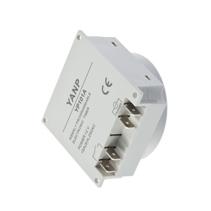
I believe theres just + -, 2 sides on the bottom of the timer. Would that not be, one set of inputs and one set of outputs for a dc timer?
Navigation
Install the app
How to install the app on iOS
Follow along with the video below to see how to install our site as a web app on your home screen.
Note: This feature may not be available in some browsers.
More options
You are using an out of date browser. It may not display this or other websites correctly.
You should upgrade or use an alternative browser.
You should upgrade or use an alternative browser.
LED Lighting Help
- Thread starter tylerandersen
- Start date
- Tagged users None
Wait, I just hunted down the pattern on the timer bottom.


- Joined
- May 27, 2013
- Messages
- 41
- Reaction score
- 1
Wait, I just hunted down the pattern on the timer bottom.

That will only do one channel so you could only switch the whites on and off but i guess thats all you would need
Yea your right, I just assumed it was set up for 2, when I glanced at his pic, didn't go hunting down the actual lead types until now. But, at $8, shouldn't be a problem running 2.
- Joined
- May 27, 2013
- Messages
- 41
- Reaction score
- 1
So on the left side the two terminals will take the wire from the negative terminal that runs to the existing switch and the wire that runs from the switch to the terminal with the green/blue cable (depending which one is for the white leds) then the right side terminals will be for the 12v + and - (making sure you get the correct polarity)
So left side I take the green negative wire connecting the white to the switch and just add it in place of the physical switch. The right side I take the positive and negative wires for the power source. I guess I'm confused on the right side. How I add it in so that it doesn't effect the blue LEDs powering.. Like I said this is all completely new for me. I appreciate your responses!
Okay got the timer! And new fans which were easy install.. So I know the switch wires go where the timer says switch.. For the power prongs, which two am I supposed to connect.. Is this just going to run through this thing to simply power it?

No I have not.. I believe it's in excess of 12v if that's what you mean.. I initially wired my 12v fans into the system and boy did they take off.. They are now running independently on 12 volts.
- Joined
- May 27, 2013
- Messages
- 41
- Reaction score
- 1
Do you have a tester to test the voltage because the fans will be more tolerable to over-voltage than the circuit board would be inside that timer and one other thing do you know the polarity (which one is positive and which one is negative) of those pins for the supply on the timer
Are the contacts for the switch actually running to the timer's board.. Or is it only the power contacts that do that and allow the switch to operate.. In other words, if I include the timer in my fans power source (12v) can I still function the lights with the switch which are powered by what's labeled as a 24v block.
Similar threads
New Posts
-
California Live Goods Stratosphere colonies and SPS 8 pack
- Latest: Tyler Drehobl
-
-
-


