MaddyP's 12G Long - Node-Red Nano Peninsula

OP
OP
MaddyP

MaddyP

'Til Reefdom Come...
View Badges
Joined
Jul 21, 2016
Messages
1,907
Reaction score
4,530
Location
Vancouver, WA
Rating - 0%
0   0   0
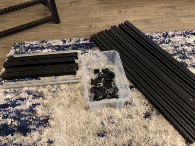
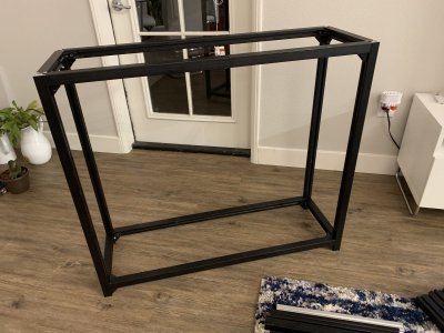
Built the stand frame out of left over Misumi t-slot pieces, not yet sure how I will skin it.
A62B2744-0B0B-475C-9A8F-B4BAB06E91B5.jpeg
B876DB84-2403-4B5E-A1DF-70694EEFC9CD.jpeg

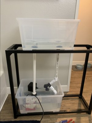
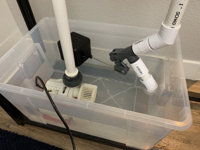
I was also able to get my concept for the drain up and running! So far, the float valve keeps the water in the top container at a constant level! The only issue I see right now is the 1” float valve is too restrictive and won’t allow enough flow to match anything above the first setting on my Varios 6. I have a 1-1/2” valve being delivered on Tuesday, hopefully it will allow a little more flow.
04AB5B71-C4B1-44EB-A387-169DFE50DFC4.jpeg
26877133-E203-47ED-BFC6-39915F9E6A44.jpeg
85244C6A-8A68-4156-8F18-911DF0E890EA.jpeg
 

theatrus

Valuable Member
View Badges
Joined
Mar 26, 2016
Messages
1,957
Reaction score
3,355
Location
Sacramento, CA area
Rating - 0%
0   0   0
Built the stand frame out of left over Misumi t-slot pieces, not yet sure how I will skin it.

A62B2744-0B0B-475C-9A8F-B4BAB06E91B5.jpeg
B876DB84-2403-4B5E-A1DF-70694EEFC9CD.jpeg

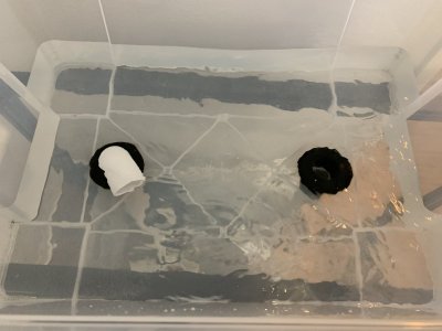
I was also able to get my concept for the drain up and running! So far, the float valve keeps the water in the top container at a constant level! The only issue I see right now is the 1” float valve is too restrictive and won’t allow enough flow to match anything above the first setting on my Varios 6. I have a 1-1/2” valve being delivered on Tuesday, hopefully it will allow a little more flow.
04AB5B71-C4B1-44EB-A387-169DFE50DFC4.jpeg
26877133-E203-47ED-BFC6-39915F9E6A44.jpeg
85244C6A-8A68-4156-8F18-911DF0E890EA.jpeg

Exciting!

Nice minimal stand. Did you have the pieces already sized or cut them yourself?
 
OP
OP
MaddyP

MaddyP

'Til Reefdom Come...
View Badges
Joined
Jul 21, 2016
Messages
1,907
Reaction score
4,530
Location
Vancouver, WA
Rating - 0%
0   0   0
Great news! Concept ran all night and “display” level remained constant!

One major consideration I’ll need to keep in mind, the displacement of water in the sump is inversely equal to the displacement of water in the display. In other words, to keep the display level from varying too much when the return pumps ramp up and down, I need to keep the surface area of water in the sump which changes levels at a minimum.

Since the float moves about 1.5” vertically from open to close and needs an area of 4.5” x 4.5” to move freely, I can limit the change in level of the display to about 1/8” so long as the return section of the sump is 4.5” x 4.5”.
 
OP
OP
MaddyP

MaddyP

'Til Reefdom Come...
View Badges
Joined
Jul 21, 2016
Messages
1,907
Reaction score
4,530
Location
Vancouver, WA
Rating - 0%
0   0   0
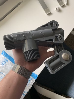
Received the 1.5" float valve today and was surprised by how big it is! Yeah, definitely won't have room for this...

DC5074AB-565B-4AAD-A830-CCE8F99D41E0.jpeg
 
Last edited:
OP
OP
MaddyP

MaddyP

'Til Reefdom Come...
View Badges
Joined
Jul 21, 2016
Messages
1,907
Reaction score
4,530
Location
Vancouver, WA
Rating - 0%
0   0   0
I guess when the simplest solution doesn't cut it, find something more complex? Since I'm using a GHL Profilux 4 for this system, I've decided to utilize a modulating automated ball valve. Similar to the automated valves I've used in the past, but this one constantly adjusts based on a 0-10V signal from the GHL. I will use a digital liquid level sensor as a "probe" for the GHL and modulate the valve via 0-10V based on that signal.

upload_2019-2-13_15-5-29.png


Last edited:

CMO

Valuable Member
View Badges
Joined
Jul 13, 2017
Messages
1,685
Reaction score
1,825
Location
Nevada City
Rating - 0%
0   0   0
I guess when the simplest solution doesn't cut it, find something more complex? Since I'm using a GHL Profilux 4 for this system, I've decided to utilize a modulating automated ball valve. Similar to the automated valves I've used in the past, but this one constantly adjusts based on a 0-10V signal from the GHL. I will use a digital liquid level sensor as a "probe" for the GHL and modulate the valve via 0-10V based on that signal.

upload_2019-2-13_15-5-29.png

Nice. But if it breaks wouldn't your whole tank drain? Any fail safe ideas?
 
OP
OP
MaddyP

MaddyP

'Til Reefdom Come...
View Badges
Joined
Jul 21, 2016
Messages
1,907
Reaction score
4,530
Location
Vancouver, WA
Rating - 0%
0   0   0
Nice. But if it breaks wouldn't your whole tank drain? Any fail safe ideas?

Add the original float valve, just fully open?

Good idea. So run the water level lower than the float in normal course.

This valve is available with built in failsafe. It has a capacitor which holds enough charge to change the valve to a pre-programmed position upon loss of power or loss of 0-10V control signal.
 

theatrus

Valuable Member
View Badges
Joined
Mar 26, 2016
Messages
1,957
Reaction score
3,355
Location
Sacramento, CA area
Rating - 0%
0   0   0
This valve is available with built in failsafe. It has a capacitor which holds enough charge to change the valve to a pre-programmed position upon loss of power or loss of 0-10V control signal.

Nice valve!

Perhaps a redundant float sensor in the tank to interrupt the control signal if the level drops?
 

CMO

Valuable Member
View Badges
Joined
Jul 13, 2017
Messages
1,685
Reaction score
1,825
Location
Nevada City
Rating - 0%
0   0   0
This valve is available with built in failsafe. It has a capacitor which holds enough charge to change the valve to a pre-programmed position upon loss of power or loss of 0-10V control signal.

But then wouldn't you run the risk of the DT overflowing in the event of a 0-10v failure but not return pump power? I guess you add a flow meter to the drain line to shut down the return pump if drain flow = zero?
 
OP
OP
MaddyP

MaddyP

'Til Reefdom Come...
View Badges
Joined
Jul 21, 2016
Messages
1,907
Reaction score
4,530
Location
Vancouver, WA
Rating - 0%
0   0   0
Nice valve!

Perhaps a redundant float sensor in the tank to interrupt the control signal if the level drops?

Yeah, I'll need to find something for this. I was thinking a low level float for "emergency low" and a continuous level sensor for the GHL.

Great work so far. Love watching this come together

Thanks! I really enjoy the design side of setting up a tank, hopefully it functions as intended!

But then wouldn't you run the risk of the DT overflowing in the event of a 0-10v failure but not return pump power? I guess you add a flow meter to the drain line to shut down the return pump if drain flow = zero?

Most likely, I'll design the return area smaller than usual so a limited amount of water can make it into the display before the pumps run dry.
 
OP
OP
MaddyP

MaddyP

'Til Reefdom Come...
View Badges
Joined
Jul 21, 2016
Messages
1,907
Reaction score
4,530
Location
Vancouver, WA
Rating - 0%
0   0   0
Another member got me thinking about redundancies to keep the display from completely draining. Here are the plausible scenarios I could think of with the programmed response. Did I miss anything?

Problem = Result
Loss of 1-10V Signal = Valve Closes 100%, Pumps start drawing air (display will hold return section volume without overflowing)
Loss of 110V Power = Valve Closes 100%, check valve in return lines close
Leak from bulkheads = Water drips back into sump
Valve closes while pumps are on = Pumps start drawing air (display will hold return section volume without overflowing)
Pump 1 fails = Valve compensates, check valve closes on return line
Pump 2 fails = Valve compensates, check valve closes on return line
Level sensor fails HIGH= Pumps start drawing air (display will hold return section volume without overflowing), emergency float (low) triggers with alarm
Level sensor fails LOW = Emergency float (HIGH) triggers and valve closes 100%
Valve fails open = Emergency float (HIGH 2) triggers and pumps turn on 100% with alarm
Valve fails closed = Pumps start drawing air (display will hold return section volume without overflowing), emergency float (low) triggers with alarm
 
Last edited:
OP
OP
MaddyP

MaddyP

'Til Reefdom Come...
View Badges
Joined
Jul 21, 2016
Messages
1,907
Reaction score
4,530
Location
Vancouver, WA
Rating - 0%
0   0   0
Here is a chart to describe my expectations on the pumps and ball valve. As the pumps vary in flow over time, the valve will change position to compensate.


upload_2019-2-15_13-5-13-png.978586


Very similar to the Tidal Swell mode of the Vortech pumps...

upload_2019-2-15_12-58-49-png.978585
 
OP
OP
MaddyP

MaddyP

'Til Reefdom Come...
View Badges
Joined
Jul 21, 2016
Messages
1,907
Reaction score
4,530
Location
Vancouver, WA
Rating - 0%
0   0   0
As the GHL gurus go over whether or not the system can handle my application, I thought of an alternative solution if GHL doesn't come through.

AVA offers a 4-20ma control option which I could pair with a 4-20ma ultrasonic sensor. This would be a stand alone system in which the sensor would communicate directly to the ball valve, bypassing GHL. With this solution the benefit would be a cleaner, industry-level communication between sensor and valve, but the downside would be lack of GHL oversight to shut things down if something else were to go wrong. The sensor below also offers built in failsafe options.

upload_2019-2-15_16-56-17.png


SPECIFICATIONS
Range: 49.2” (1.25m)
Accuracy: 0.125” (3mm)
Resolution: 0.019” (0.5mm)
Dead band: 2” (5cm)
Beam width: 2” (5cm)
Configuration: WebCal™ PC, Windows®, USB 2.0
Memory: Non-volatile
Supply voltage: 24 VDC (loop)
Consumption: 0.5W
Loop resist.: 400Ω max
Signal output: 4-20 mA, two-wire
Signal invert: 4-20 mA or 20-4mA
Loop fail-safe: 4 mA, 20 mA, 21 mA, 22 mA or hold last
Process temp.: F: 20° to 140°, C: -7° to 60°
Temp. comp.: Automatic
Ambient temp.: F: -31° to 140°, C: -35° to 60°
Cable length: 48” (1.2m)
Process mount: 1” NPT (1” G)
 
Last edited:

eschulist

Active Member
View Badges
Joined
Apr 4, 2012
Messages
352
Reaction score
802
Location
Minneapolis
Rating - 0%
0   0   0
I’m pretty sure I suffer from this but you have taken it to another level.

Second System Effect

The second-system effect (also known as second-system syndrome) is the tendency of small, elegant, and successful systems, to be succeeded by over-engineered, bloated systems, due to inflated expectations and overconfidence.

I wish you all the luck in getting this design to work. A tank with no visible bulkheads, valves, pipes, cords and equipment while still maintaining a constant level without overflowing will look amazing.
 
OP
OP
MaddyP

MaddyP

'Til Reefdom Come...
View Badges
Joined
Jul 21, 2016
Messages
1,907
Reaction score
4,530
Location
Vancouver, WA
Rating - 0%
0   0   0
I’m pretty sure I suffer from this but you have taken it to another level.

Second System Effect

The second-system effect (also known as second-system syndrome) is the tendency of small, elegant, and successful systems, to be succeeded by over-engineered, bloated systems, due to inflated expectations and overconfidence.

I wish you all the luck in getting this design to work. A tank with no visible bulkheads, valves, pipes, cords and equipment while still maintaining a constant level without overflowing will look amazing.
You might just be right...and it might just work...
 

theatrus

Valuable Member
View Badges
Joined
Mar 26, 2016
Messages
1,957
Reaction score
3,355
Location
Sacramento, CA area
Rating - 0%
0   0   0
As the GHL gurus go over whether or not the system can handle my application, I thought of an alternative solution if GHL doesn't come through.

AVA offers a 4-20ma control option which I could pair with a 4-20ma ultrasonic sensor. This would be a stand alone system in which the sensor would communicate directly to the ball valve, bypassing GHL. With this solution the benefit would be a cleaner, industry-level communication between sensor and valve, but the downside would be lack of GHL oversight to shut things down if something else were to go wrong. The sensor below also offers built in failsafe options.

upload_2019-2-15_16-56-17.png


SPECIFICATIONS
Range: 49.2” (1.25m)
Accuracy: 0.125” (3mm)
Resolution: 0.019” (0.5mm)
Dead band: 2” (5cm)
Beam width: 2” (5cm)
Configuration: WebCal[emoji769] PC, Windows[emoji2400], USB 2.0
Memory: Non-volatile
Supply voltage: 24 VDC (loop)
Consumption: 0.5W
Loop resist.: 400Ω max
Signal output: 4-20 mA, two-wire
Signal invert: 4-20 mA or 20-4mA
Loop fail-safe: 4 mA, 20 mA, 21 mA, 22 mA or hold last
Process temp.: F: 20° to 140°, C: -7° to 60°
Temp. comp.: Automatic
Ambient temp.: F: -31° to 140°, C: -35° to 60°
Cable length: 48” (1.2m)
Process mount: 1” NPT (1” G)

Having a stand alone is very compelling, but you’ll need to add some analog computer (mostly scaling) to get it to work. My personal take would be to build a stand alone controller for this out of any available microcontroller which is predictable and not subject to updates, power on lag, etc etc.

I don’t have experience with GHLs control system.
 

Creating a strong bulwark: Did you consider floor support for your reef tank?

  • I put a major focus on floor support.

    Votes: 51 42.1%
  • I put minimal focus on floor support.

    Votes: 25 20.7%
  • I put no focus on floor support.

    Votes: 42 34.7%
  • Other.

    Votes: 3 2.5%
Back
Top