




Hello,
I would like to build my own DIY battery backup system.
I had some basic schematics in my head and it would be appreciated if I could get your thought about this.
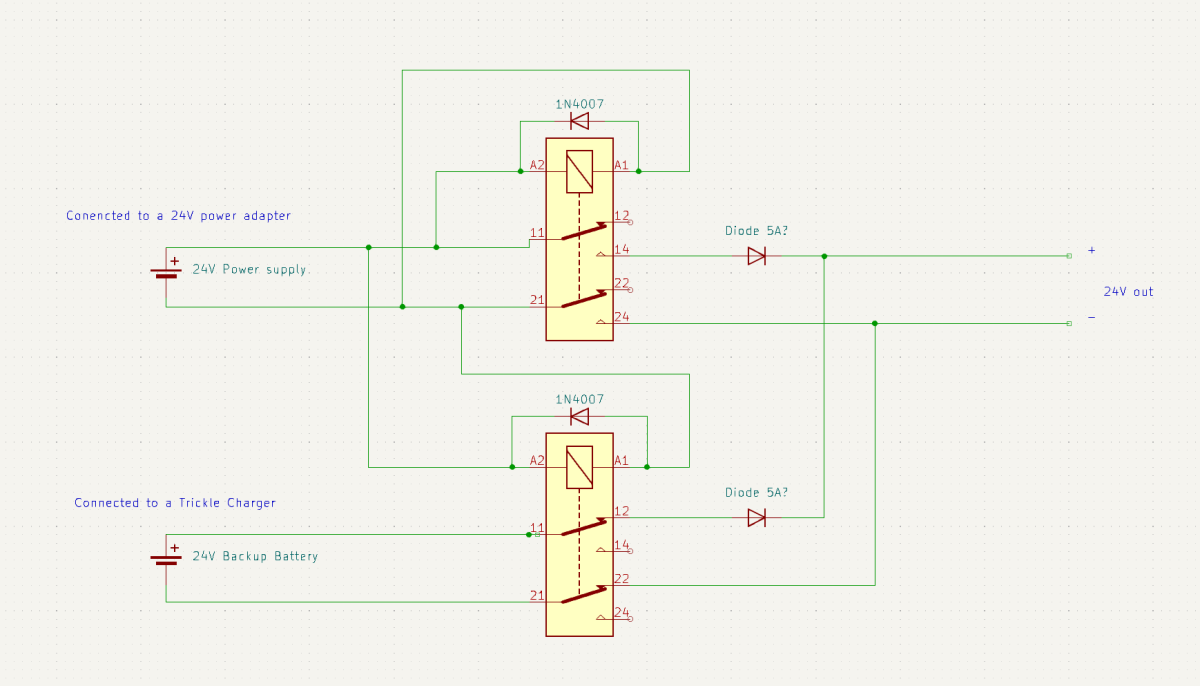
I have the normal power supply relay terminals wired as N/O and the battery relay terminals connected as N/C.
When the power adapter got power, the main power supply will be connected to the 24V output, and the battery terminals will be disconnected.
When the power fails, the power adapter will disconnect and the battery terminals will connect to the 24V output.
Do you all think this will be a good solution or are there some flaws in the schematics?
My consern right now is the battery relay powered 24/7 until a power failure accures (which might happen the next month, or maybe after a year?)
Is it oke to keep the relay powered on for such a long time?
Any tips on improving my schematic are highly appreciated.
It will only be used to power two 24V-20W powerheads so I guess the total output will be about 24V 2-3A
I would like to build my own DIY battery backup system.
I had some basic schematics in my head and it would be appreciated if I could get your thought about this.
I have the normal power supply relay terminals wired as N/O and the battery relay terminals connected as N/C.
When the power adapter got power, the main power supply will be connected to the 24V output, and the battery terminals will be disconnected.
When the power fails, the power adapter will disconnect and the battery terminals will connect to the 24V output.
Do you all think this will be a good solution or are there some flaws in the schematics?
My consern right now is the battery relay powered 24/7 until a power failure accures (which might happen the next month, or maybe after a year?)
Is it oke to keep the relay powered on for such a long time?
Any tips on improving my schematic are highly appreciated.
It will only be used to power two 24V-20W powerheads so I guess the total output will be about 24V 2-3A
Last edited:











