problem controling a nicrew 50W lamp

bishoptf

Valuable Member
View Badges
Joined
Jan 1, 2019
Messages
1,344
Reaction score
1,722
Location
Missouri
Rating - 0%
0   0   0
Interesting, what do you get for 2% ?

Regarding the safety, I was talking about the blue wire going from capacitor to the jack in the fritzing diagram. Well, to add safety is a bit tricky in fritzing, due to the limitation in placement. Personally, I would simply solder a 1k resistor into the blue wire, but that's not quite good enough for a guide I believe :grinning-face-with-sweat:

Here's something one could do on the board although it would eat up even more space:
1675110474264.png
Yeah I need to move everything around on my diagram, thats what I was thinking and you said 1k, right?

1% - .152
2% - .232
7%(turn on) -.697
 

bishoptf

Valuable Member
View Badges
Joined
Jan 1, 2019
Messages
1,344
Reaction score
1,722
Location
Missouri
Rating - 0%
0   0   0
This would at least limit peak current at 10V to 10mA, which isn't that dangerous anymore.
Yeah I will have to move a lot of stuff around on how I had mine laid out, ugh...makes sense though but not sure what we are really protecting, the nicrew light or what? I guess you could touch the ends of the trs plug.
 
OP
OP
S

Sral

Valuable Member
View Badges
Joined
May 2, 2022
Messages
1,006
Reaction score
976
Location
Germany
Rating - 0%
0   0   0
Yeah, 1k should be enough, it's the same as the original guide anyway.
To fit that on the board you would need to move each unit one hole to the right. You can select multiple components by holding down CTRL, so you can move them all at once.

We are protecting both the user and the capacitor, mostly. 20mA is starting to become serious and we are in that rough range. It will likely only go over the jack and/or burn the skin on your finger locally, but better be safe than sorry´. The cap might also blow if it is discharged too rapidly, as well as the jack sparking and possibly damaging both the jack and the connector on the light. Definitely not a good thing.

Curious about the voltage at 1 and 2%. Not sure how that is possible, but I guess I just don't quite understand bipolar transistor operation at these low currents and voltages. That also means that one wouldn't even need to change to a MOSFET to get very low signals. Nice.
 
Last edited:

bishoptf

Valuable Member
View Badges
Joined
Jan 1, 2019
Messages
1,344
Reaction score
1,722
Location
Missouri
Rating - 0%
0   0   0
Yeah, 1k should be enough, it's the same as the original guide anyway.
To fit that on the board you would need to move each unit one hole to the right. You can select multiple components by holding down CTRL, so you can move them all at once.

We are protecting both the user and the capacitor, mostly. 20mA is starting to become serious and we are in that rough range. It will likely only go over the jack and/or burn the skin on your finger locally, but better be safe than sorry´. The cap might also blow if it is discharged too rapidly, as well as the jack sparking and possibly damaging both the jack and the connector on the light. Definitely not a good thing.

Curious about the voltage at 1 and 2%. Not sure how that is possible, but I guess I just don't quite understand bipolar transistor operation at these low currents and voltages. That also means that one wouldn't even need to change to a MOSFET to get very low signals. Nice.
Here is the updated diagram, take a look and see if I messed anything up...

nicrew_bb.png

I had fun learning how to rotate the bloody resistor...lol.
 
OP
OP
S

Sral

Valuable Member
View Badges
Joined
May 2, 2022
Messages
1,006
Reaction score
976
Location
Germany
Rating - 0%
0   0   0
Here is the updated diagram, take a look and see if I messed anything up...

nicrew_bb.png

I had fun learning how to rotate the bloody resistor...lol.
Looks great ! Nothing wrong that I can see.

Except, one worry: do we also need to connect the PCA9685‘s V+ to 5V and will that also pull up the I2C lines to 5V ? Can’t remember from the top of my head how the Adafruit PWM board is built in this regard.
 

bishoptf

Valuable Member
View Badges
Joined
Jan 1, 2019
Messages
1,344
Reaction score
1,722
Location
Missouri
Rating - 0%
0   0   0
Looks great ! Nothing wrong that I can see.

Except, one worry: do we also need to connect the PCA9685‘s V+ to 5V and will that also pull up the I2C lines to 5V ? Can’t remember from the top of my head how the Adafruit PWM board is built in this regard.
Look really really closely, what was said last time *snicker*....:)

Now I need to figure out how to bodge my board one more time, ugh...
 
OP
OP
S

Sral

Valuable Member
View Badges
Joined
May 2, 2022
Messages
1,006
Reaction score
976
Location
Germany
Rating - 0%
0   0   0
Look really really closely, what was said last time *snicker*....:)

Now I need to figure out how to bodge my board one more time, ugh...
Yeah, it’s a never ending story :face-with-tears-of-joy:

Well, you could simply solder the resistor into the cable and put some heatshrink over it.
 

bishoptf

Valuable Member
View Badges
Joined
Jan 1, 2019
Messages
1,344
Reaction score
1,722
Location
Missouri
Rating - 0%
0   0   0
OP
OP
S

Sral

Valuable Member
View Badges
Joined
May 2, 2022
Messages
1,006
Reaction score
976
Location
Germany
Rating - 0%
0   0   0

robsworld78

Well-Known Member
View Badges
Joined
Feb 14, 2020
Messages
952
Reaction score
1,281
Location
Edmonton, Canada
Rating - 0%
0   0   0
I have looked it up as well and it does have 10k pull-ups to VCC. @Ranjib So if we power the board with 5V doesn’t that mean that we possibly overvolt the PI‘s pins ?
Yeah as the pca9685 module has 10k pullups the SCL/SDA are trying to go to the input voltage. The Pi has pullups built in pulling up to 3.3v and if my memory serves correct they end up settling around 4.1v however that was on an Arduino with 10k external pullups to 3.3v. If the built in resistors on the Pi are weak it might be higher voltage or maybe they are stronger and it's lower voltage, I think it's a case of the strongest win? Ideally one could remove the resistors on the pca9685 module. With that said an Arduino Due, 3.3v based, was ok with the higher voltage.
 
OP
OP
S

Sral

Valuable Member
View Badges
Joined
May 2, 2022
Messages
1,006
Reaction score
976
Location
Germany
Rating - 0%
0   0   0
Well, if you restructure it it looks like this:
1675149486512.png

You can replace that Pi with an Arduino Duo, works the same except for absolute maximum voltage rating.

All pull-ups to different voltages form a resistance divider between the voltage rails with the I2C lines (SDA and SCL) in the middle. Builtin pull-up and pull-down resistors on microchips are typically very large, on the order of 40-70k, as far as I am informed.
If you have no external pull-up to 3.3V, the 10k wins, since it provides more current, e.g. the "stronger" pull-up.
V_SDA = 3.3V + (5.0V - 3.3V) * 50k / (50k + 10k) ~ 4.72 V

If you include the external pull-up you have about 10k to both lines, making the SDA settle pretty much in the middle:
V_SDA = 3.3V + (5.0V - 3.3V) * 10k / (10k + 10k) ~ 4.15 V

(a parallel 10k and 50k equal a resistance of about 8.3k, which is roughly equal to 10k).


So connecting the PCA9685 directly to the 5V might not be a good idea. One can however connect the PCA9685 to the PI's 3.3V, that would work perfectly. 3.3V is enough to power both the PCA9685 and also run the npn transistors, although I would recommend a small capacitor in the PCA9685 circuit, like a 100nF or 1µF so current draw peaks do not tax the PI's 3.3V line so much that the PI crashes.
 

bishoptf

Valuable Member
View Badges
Joined
Jan 1, 2019
Messages
1,344
Reaction score
1,722
Location
Missouri
Rating - 0%
0   0   0
So whats the bottom line, do I have it laid out correctly in the fritz going to vcc or? I was just going off what @Ranjib had in his earlier diagram...
 
OP
OP
S

Sral

Valuable Member
View Badges
Joined
May 2, 2022
Messages
1,006
Reaction score
976
Location
Germany
Rating - 0%
0   0   0
So whats the bottom line, do I have it laid out correctly in the fritz going to vcc or? I was just going off what @Ranjib had in his earlier diagram...
Well, I don't know if anybody actually tested the guide for a longer time. Judging from the Guide he (@Ranjib) directly connected the PI's SDA and SCL to the PCA9685 and powered everything with 5V. Don't know if that setup survived long enough to damage the pins though.

The safe option would be to connect the PCA9685 with 3.3V, but since I don't believe that anybody actually followed those guides to the letter, I don't think you need to rework yours now.
 

bishoptf

Valuable Member
View Badges
Joined
Jan 1, 2019
Messages
1,344
Reaction score
1,722
Location
Missouri
Rating - 0%
0   0   0
Well, I don't know if anybody actually tested the guide for a longer time. Judging from the Guide he (@Ranjib) directly connected the PI's SDA and SCL to the PCA9685 and powered everything with 5V. Don't know if that setup survived long enough to damage the pins though.

The safe option would be to connect the PCA9685 with 3.3V, but since I don't believe that anybody actually followed those guides to the letter, I don't think you need to rework yours now.
I think I understand now what the issue is, I could remove the rpi reference altogether, lol. I was just trying to make it like his old lighting guide.
 

robsworld78

Well-Known Member
View Badges
Joined
Feb 14, 2020
Messages
952
Reaction score
1,281
Location
Edmonton, Canada
Rating - 0%
0   0   0
Well, if you restructure it it looks like this:
1675149486512.png

You can replace that Pi with an Arduino Duo, works the same except for absolute maximum voltage rating.

All pull-ups to different voltages form a resistance divider between the voltage rails with the I2C lines (SDA and SCL) in the middle. Builtin pull-up and pull-down resistors on microchips are typically very large, on the order of 40-70k, as far as I am informed.
If you have no external pull-up to 3.3V, the 10k wins, since it provides more current, e.g. the "stronger" pull-up.
V_SDA = 3.3V + (5.0V - 3.3V) * 50k / (50k + 10k) ~ 4.72 V

If you include the external pull-up you have about 10k to both lines, making the SDA settle pretty much in the middle:
V_SDA = 3.3V + (5.0V - 3.3V) * 10k / (10k + 10k) ~ 4.15 V

(a parallel 10k and 50k equal a resistance of about 8.3k, which is roughly equal to 10k).


So connecting the PCA9685 directly to the 5V might not be a good idea. One can however connect the PCA9685 to the PI's 3.3V, that would work perfectly. 3.3V is enough to power both the PCA9685 and also run the npn transistors, although I would recommend a small capacitor in the PCA9685 circuit, like a 100nF or 1µF so current draw peaks do not tax the PI's 3.3V line so much that the PI crashes.
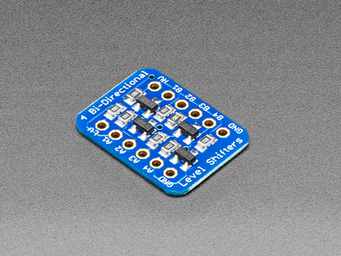
Yeah max voltage rating might not be as high on Pi but I have a feeling quite a few are using 5v and the Pi is managing. Back in the day when I first used the Arduino Due I had the pca9685 mocked up like the schematic you posted but also put 10k to 3.3v, when I did some voltage tests I realized I messed up as I had 4.1v so starting using the BSS138 to convert the voltages as I didn't want 0-3.3v PWM out. That's the downside to powering with 3.3v, most devices want 0-5v or greater so you always need an extra circuit. I think powering with 5v and using one of these is better.


I also have a feeling I2C is more reliable at higher voltage.
 
OP
OP
S

Sral

Valuable Member
View Badges
Joined
May 2, 2022
Messages
1,006
Reaction score
976
Location
Germany
Rating - 0%
0   0   0
Yeah max voltage rating might not be as high on Pi but I have a feeling quite a few are using 5v and the Pi is managing. Back in the day when I first used the Arduino Due I had the pca9685 mocked up like the schematic you posted but also put 10k to 3.3v, when I did some voltage tests I realized I messed up as I had 4.1v so starting using the BSS138 to convert the voltages as I didn't want 0-3.3v PWM out. That's the downside to powering with 3.3v, most devices want 0-5v or greater so you always need an extra circuit. I think powering with 5v and using one of these is better.


I also have a feeling I2C is more reliable at higher voltage.
You are probably right, although I would not trust this to work as long in my own setup.

The BSS138 is pretty good, if you have to slow down I2C for the pH circuit anyway this is absolutely fine. I2C at higher voltages might be more reliable because 5V provides a faster pull-up past the "LOW" threshold somewhere around 0.8V and the "HIGH" threshold somewhere past 2.5V or so.
 

theatrus

Valuable Member
View Badges
Joined
Mar 26, 2016
Messages
1,951
Reaction score
3,353
Location
Sacramento, CA area
Rating - 0%
0   0   0
Yeah max voltage rating might not be as high on Pi but I have a feeling quite a few are using 5v and the Pi is managing. Back in the day when I first used the Arduino Due I had the pca9685 mocked up like the schematic you posted but also put 10k to 3.3v, when I did some voltage tests I realized I messed up as I had 4.1v so starting using the BSS138 to convert the voltages as I didn't want 0-3.3v PWM out. That's the downside to powering with 3.3v, most devices want 0-5v or greater so you always need an extra circuit. I think powering with 5v and using one of these is better.


I also have a feeling I2C is more reliable at higher voltage.

The clamping/ESD diodes on the Pi will always be conducting when above Vcc of the IO section (3.3V). The question is how much power can they dissipate, which may not be specced. Weaker pull-ups will of course help reduce the power bleeding through them.

And I2C at higher voltages gives you more margin for sure. As will stronger pull-ups (on 400kHz I go to 2.2k), which of course is contraindicated when attaching a 5V bus to the 3.3V Pi.

Since HDMI DDC (the part that does display detection and control) is just I2C, there are solutions for active drivers there too, useful for long cable lengths (meters of cable). Most are 5V translating as well. Example: https://www.nxp.com/docs/en/data-sheet/PCA9527.pdf. You can ignore the CEC bus.
 

robsworld78

Well-Known Member
View Badges
Joined
Feb 14, 2020
Messages
952
Reaction score
1,281
Location
Edmonton, Canada
Rating - 0%
0   0   0
The clamping/ESD diodes on the Pi will always be conducting when above Vcc of the IO section (3.3V). The question is how much power can they dissipate, which may not be specced. Weaker pull-ups will of course help reduce the power bleeding through them.

And I2C at higher voltages gives you more margin for sure. As will stronger pull-ups (on 400kHz I go to 2.2k), which of course is contraindicated when attaching a 5V bus to the 3.3V Pi.

Since HDMI DDC (the part that does display detection and control) is just I2C, there are solutions for active drivers there too, useful for long cable lengths (meters of cable). Most are 5V translating as well. Example: https://www.nxp.com/docs/en/data-sheet/PCA9527.pdf. You can ignore the CEC bus.
Wow didn't know I2C is being used like that, I find that shocking. Obviously it's not doing anything critical but I2C wasn't made for this sort of thing.
 

theatrus

Valuable Member
View Badges
Joined
Mar 26, 2016
Messages
1,951
Reaction score
3,353
Location
Sacramento, CA area
Rating - 0%
0   0   0
Wow didn't know I2C is being used like that, I find that shocking. Obviously it's not doing anything critical but I2C wasn't made for this sort of thing.

In some ways, it was. A meter or two of cable was part of the I2C design.

I suspect this idea was an offshoot of how RAM sticks are identified - the SPD identifier is a very cheap I2C EEPROM chip, giving capacity and timings. The DDC interface is basically a cheap EEPROM, just in the monitor, and was an option in VGA and DVI too for figuring out resolutions and refresh rates supported.
 

robsworld78

Well-Known Member
View Badges
Joined
Feb 14, 2020
Messages
952
Reaction score
1,281
Location
Edmonton, Canada
Rating - 0%
0   0   0
In some ways, it was. A meter or two of cable was part of the I2C design.
The student feels he has to push back on the professor for this statement. :rolling-on-the-floor-laughing:

That seems pretty optimistic, anytime I read technical data on I2C it always says don't leave the PCB. I just spent a couple hours going through more hoping to find actual specs in my favor but i2c-bus.org says it's not available.

Unfortunatelly the recent I²C-bus Specification, NXP document Version 6.0, 4th of April 2014 is not available for public on the NXP site anymore.

Then I landed on the I2C wiki page and it says the following.

The vast majority of applications use I2C in the way it was originally designed—peripheral ICs directly wired to a processor on the same printed circuit board, and therefore over relatively short distances of less than 1 foot (30 cm), without a connector. However using a differential driver, an alternate version of I2C can communicate up to 20 meters (possibly over 100 meters) over CAT5 or other cable.


Adafruit echos the same and many others do as well.


And while I'm posting links I always liked this article as it's readable for someone like me. He also echoes this at the end of the first paragraph.


Now when I make PCB's the first thing I do is layout the I2C to be as short as possible and no Y's. This is the latest and cleanest I've had so I got to show it off. Out of Pi into BSS138 to go to 5v, then into PCA9685, then into DS1307, then into ISO1540 and finally to header pins which I hate but being DIY they have to be.

i2c_traces.jpg
 

Clear reef vision: How do you clean the inside of the glass on your aquarium?

  • Razor blade

    Votes: 133 59.9%
  • Plastic scraper

    Votes: 64 28.8%
  • Clean-up crew

    Votes: 79 35.6%
  • Magic eraser

    Votes: 39 17.6%
  • Other

    Votes: 63 28.4%
Back
Top