
- Joined
- Oct 3, 2019
- Messages
- 679
- Reaction score
- 695
Some of my previous repairs:

 www.reef2reef.com
www.reef2reef.com
www.reef2reef.com
www.reef2reef.com
www.reef2reef.com
And as always, uncensored, updated and corrected versions of my repair articles are a quick internet search away.
So many Radion repairs due to blown LEDs! It's time to discuss something different.
This time, a fellow reefer sent me an XR30 light, which shuts off entirely as soon as the intensity on the blue channel is increased above 15-30%.
Mind you, there is no light on the red channel at all as well no matter what, this made me suspect that yet another red LED is blown. After all, I struggle to keep red LEDs in stock given how often I have to replace them.
However, this story is going to be different.
Not only does the light shuts off at a mildly higher intensity setting, it requires a power reset to get it back on. The cycle repeats every time the intensity is increased.
And why is the blue channel affected if the red channel is not working? Let's dive in and find out what is causing this behavior.
First, this light is a couple of years old. Thus, it is reasonable to expect that it will have some corrosion on the main board. I also have a few other boards in a similar condition. Let's give them a good ultrasonic bath:

And a rinse:

Now that all of the salt and dirt is gone. It's time for a visual inspection under the microscope.
Wait a minute, this is not what it's supposed to look like:

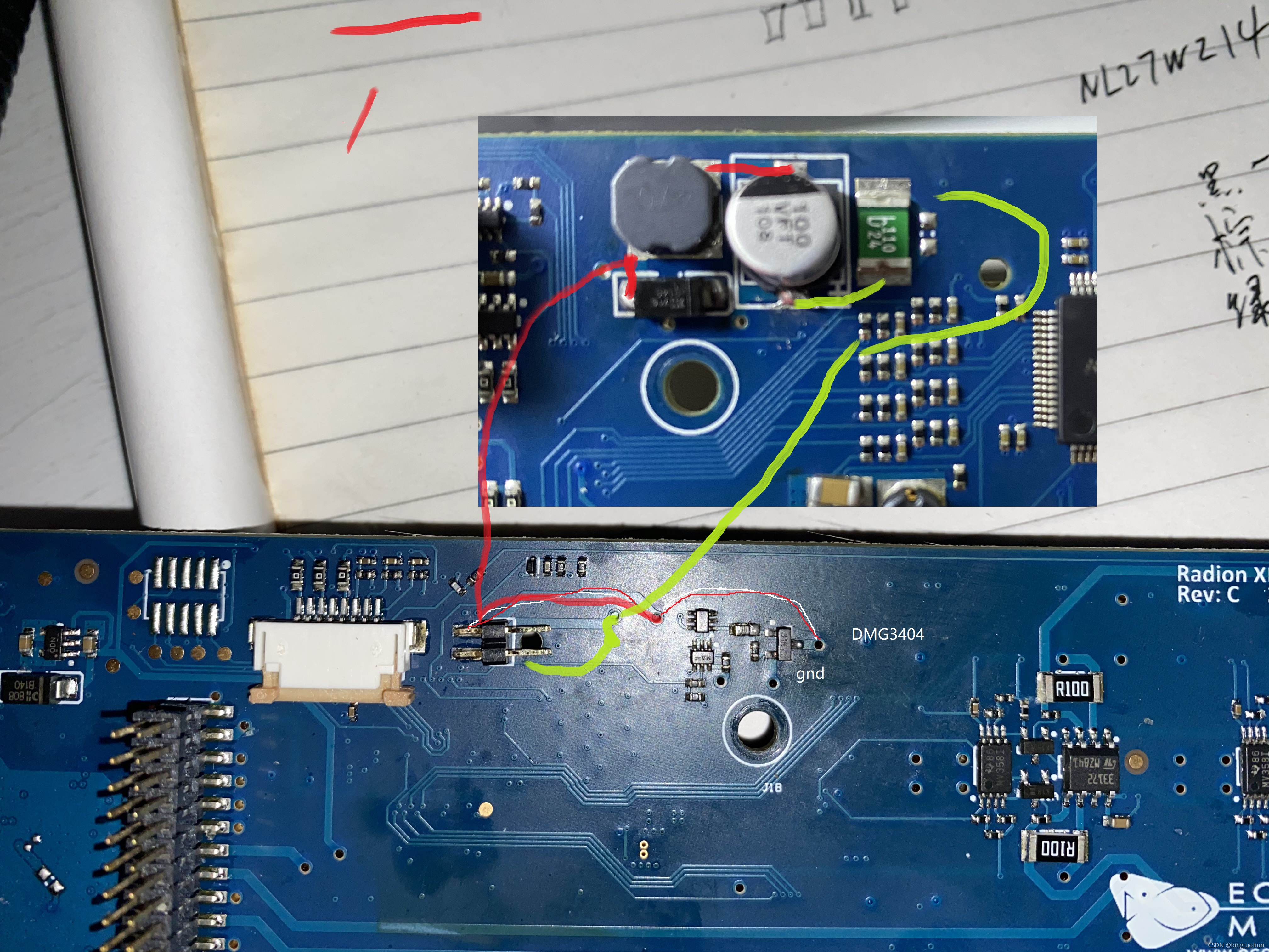
You are looking at a dual channel power MOSFET. It provides power to the red and the blue channels of the light. Something tells me that the gaping hole on one side, the cracked case and the burn mark on the board have something to do with the red channel not working. Here's an interesting tidbit: again, this is a two channel MOSFET, it serves two channels independently. One channel is red, the other channel is blue. The blue channel actually works somewhat. This tells me that the other side of this chip is actually working.
Naturally, the first reaction to the above is that all we need to do is replace the burned MOSFET and call it a day.
Not a chance:

Apparently, there are other holes. This one above is a dual channel OpAmp. It also serves two LED channels. Any guess as to which ones?
That's right - red and blue. And the hole is on the red channel. From the two current sensing resistors around the OpAmp, we conclude that it's responsible for handling current sensing circuitry for these two channels.
And speaking of the hole. Here's a close up:


Alright, thankfully no more holes. Oh, wait. How about some melting:

Above is another, smaller MOSFET. And once again, it is on the red channel. The plot thickens rapidly.
So far, we have three major components up for replacement. So let's go ahead and do that.
First, remove the smaller melted MOSFET:

After cleaning up the site, here's the condition we find the board:

One pad is clearly missing. It melted away with the MOSFET when it shorted. That's OK, I restore pads like this daily:


Not bad. There is now a fairly thick copper conductor connecting the pin and the resistor.
Next, we'll remove the blown OpAmp and clean up the site to assess the damage:


And replace it with a new OpAmp:

Finally, the large power MOSFET is gone and replaced:


Everything looks great. Surely the light will now work.
Not really. When I plug in the power, my bench power supply quickly reaches the maximum preset current indicating a short!
Ah, so that's why everything has melted before. Radion drives some very serious current to each LED channel. If a component in the circuit fails and shorts it to ground, the entire circuit is doomed.
So which component is causing the short? Let's set the PSU to some very low current so as to not damage the circuit and use some alcohol to see if anything heats up:

Wait a minute, isn't this the power MOSFET I just replaced???
Notice that the alcohol evaporates only on one side of the MOSFET. It happens on the same side where the previous MOSFET blew up.
Good thing I'm not running the full current through this component. Otherwise, there would have been another hole in it by now.
But this is a known good MOSFET. It should not be causing a short...
As I'm testing the MOSFET, I accidentally touched the diode that it's connected to:

It was HOT!. I couldn't even capture alcohol evaporation on it. Testing the diode turned out that the diode is clearly shorted. This was likely the root cause of the original failure.
Gone and replaced:


After replacing the diode, the power MOSFET is no longer heating up. The short is gone.
But the light is still not turning on... didn't we have enough already?
Looking for any other shorts on the channel, we came across this:

Yet another OpAmp on the red channel circuit. Likely shorted. Replaced:


And then there is suspicious component. It's another low power dual channel MOSFET:

When removed, we can clearly see the problem - a corner is completely gone. This chip was also damaged by the original short:

Removed and replaced:


By now, the entire red channel circuit has been replaced: Three MOSFETS, Two OpAmps and the diode.
The red channel works again. Not only that but the blue channel can also be brought up to the highest intensity without shutting the light off.

And this XR30 is happy again.
The leading theory as to what happened here is that the red channel shorted causing the entire circuit to blow up. But since the blue channel shares several components with the red channel, it also got affected. What is interesting here is that the blue channel still worked at very low intensity, suggesting that half of the blown chip, which belongs to the blue channel was still working while the other half either melted or developed a hole.
Radion XR30 complete no light repair
My previous electronic equipment repairs Radion XR15: https://www.reef2reef.com/threads/radion-lights-board-level-repair.774331/#post-8197536 A fellow reefer mailed me their Ecotech Radion for repair service as it's long been out of warranty. The unit turns on briefly before shutting down and...
Radion XR15 doesn't power on due to corrosion repair
Some of my previous repairs: https://www.reef2reef.com/threads/radion-xr30-complete-no-light-repair.792711/ https://www.reef2reef.com/threads/another-attempt-at-fixing-apex-eb832.804717/ https://www.reef2reef.com/threads/ai-hydra-fan-connector-repair-significant-corrosion.793402/ And as always...
Another attempt at fixing Apex EB832
Some of my previous repairs: https://www.reef2reef.com/threads/radion-xr30-complete-no-light-repair.792711/ https://www.reef2reef.com/threads/radion-lights-board-level-repair.774331/ https://www.reef2reef.com/threads/ai-hydra-fan-connector-repair-significant-corrosion.793402/ First off, let me...
And as always, uncensored, updated and corrected versions of my repair articles are a quick internet search away.
So many Radion repairs due to blown LEDs! It's time to discuss something different.
This time, a fellow reefer sent me an XR30 light, which shuts off entirely as soon as the intensity on the blue channel is increased above 15-30%.
Mind you, there is no light on the red channel at all as well no matter what, this made me suspect that yet another red LED is blown. After all, I struggle to keep red LEDs in stock given how often I have to replace them.
However, this story is going to be different.
Not only does the light shuts off at a mildly higher intensity setting, it requires a power reset to get it back on. The cycle repeats every time the intensity is increased.
And why is the blue channel affected if the red channel is not working? Let's dive in and find out what is causing this behavior.
First, this light is a couple of years old. Thus, it is reasonable to expect that it will have some corrosion on the main board. I also have a few other boards in a similar condition. Let's give them a good ultrasonic bath:
And a rinse:
Now that all of the salt and dirt is gone. It's time for a visual inspection under the microscope.
Wait a minute, this is not what it's supposed to look like:
You are looking at a dual channel power MOSFET. It provides power to the red and the blue channels of the light. Something tells me that the gaping hole on one side, the cracked case and the burn mark on the board have something to do with the red channel not working. Here's an interesting tidbit: again, this is a two channel MOSFET, it serves two channels independently. One channel is red, the other channel is blue. The blue channel actually works somewhat. This tells me that the other side of this chip is actually working.
Naturally, the first reaction to the above is that all we need to do is replace the burned MOSFET and call it a day.
Not a chance:
Apparently, there are other holes. This one above is a dual channel OpAmp. It also serves two LED channels. Any guess as to which ones?
That's right - red and blue. And the hole is on the red channel. From the two current sensing resistors around the OpAmp, we conclude that it's responsible for handling current sensing circuitry for these two channels.
And speaking of the hole. Here's a close up:
Alright, thankfully no more holes. Oh, wait. How about some melting:
Above is another, smaller MOSFET. And once again, it is on the red channel. The plot thickens rapidly.
So far, we have three major components up for replacement. So let's go ahead and do that.
First, remove the smaller melted MOSFET:
After cleaning up the site, here's the condition we find the board:
One pad is clearly missing. It melted away with the MOSFET when it shorted. That's OK, I restore pads like this daily:
Not bad. There is now a fairly thick copper conductor connecting the pin and the resistor.
Next, we'll remove the blown OpAmp and clean up the site to assess the damage:
And replace it with a new OpAmp:
Finally, the large power MOSFET is gone and replaced:
Everything looks great. Surely the light will now work.
Not really. When I plug in the power, my bench power supply quickly reaches the maximum preset current indicating a short!
Ah, so that's why everything has melted before. Radion drives some very serious current to each LED channel. If a component in the circuit fails and shorts it to ground, the entire circuit is doomed.
So which component is causing the short? Let's set the PSU to some very low current so as to not damage the circuit and use some alcohol to see if anything heats up:
Wait a minute, isn't this the power MOSFET I just replaced???
Notice that the alcohol evaporates only on one side of the MOSFET. It happens on the same side where the previous MOSFET blew up.
Good thing I'm not running the full current through this component. Otherwise, there would have been another hole in it by now.
But this is a known good MOSFET. It should not be causing a short...
As I'm testing the MOSFET, I accidentally touched the diode that it's connected to:
It was HOT!. I couldn't even capture alcohol evaporation on it. Testing the diode turned out that the diode is clearly shorted. This was likely the root cause of the original failure.
Gone and replaced:
After replacing the diode, the power MOSFET is no longer heating up. The short is gone.
But the light is still not turning on... didn't we have enough already?
Looking for any other shorts on the channel, we came across this:
Yet another OpAmp on the red channel circuit. Likely shorted. Replaced:
And then there is suspicious component. It's another low power dual channel MOSFET:
When removed, we can clearly see the problem - a corner is completely gone. This chip was also damaged by the original short:
Removed and replaced:
By now, the entire red channel circuit has been replaced: Three MOSFETS, Two OpAmps and the diode.
The red channel works again. Not only that but the blue channel can also be brought up to the highest intensity without shutting the light off.
And this XR30 is happy again.
The leading theory as to what happened here is that the red channel shorted causing the entire circuit to blow up. But since the blue channel shares several components with the red channel, it also got affected. What is interesting here is that the blue channel still worked at very low intensity, suggesting that half of the blown chip, which belongs to the blue channel was still working while the other half either melted or developed a hole.