

Nope I didn't change anything. That's just how it was. I should have gotten a pic of the top too before I put it all away haha. I thought I saw 4 white wires going into the top.
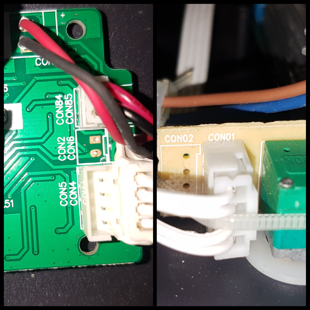
Looking back at the pics it looks like the 4 wires from the driver go into the row of 4 dots of solder above the empty ones.
I see now. The de-soldered pins are south of the female connection. I would have to think that this 4wire setup is 0-10v analog... Someone else will have to chime in to confirm.