reef-pi :: An opensource reef tank controller based on Raspberry Pi.

OP
OP
Ranjib

Ranjib

7500 Club Member
View Badges
Joined
Apr 16, 2016
Messages
9,847
Reaction score
17,077
Location
Pleasant Hill, Concord
Rating - 0%
0   0   0
Cool, I can start taking little bites here and there. I still have a ways to go before I even start my tank, I bought a cracked tank and that's the only thing I have so far. Lol. I feel that automation from the beginning will provide the best chance of success. Yes, I'm sure knowing (figuring out) the proper parameters for my tank play a huge part in keeping everything alive but once that's figured out it can become more automated. Automation will help immensely with still having three young children and going to school full time. Stress makes folks forgetful. Haha

You know I used to think that too. And too large extent i still agree, having automation make life so much better.

But, I realized over the past couple of years, that whats best for my tank is not very extensive automation, just little bit here and there , to complement the pain staking parts, and to tell me if things are horribly wrong. For the most part, its the simplest thing like just outlet controls that provided highest return of investment. The peace of mind factors (i can see tank temperature, photo , ato status etc while im in vacation) also paid off immensely
 

U_ser_ID

Community Member
View Badges
Joined
Feb 10, 2018
Messages
60
Reaction score
42
Rating - 0%
0   0   0
@Ranjib I had a response but I keep getting words in my ear, thanks for the input. I appreciate it. Maybe later I'll regain my slightly intelligent response.. lol
 

Gareth elliott

Read, Tinker, Fail, Learn
View Badges
Joined
May 7, 2017
Messages
5,468
Reaction score
6,936
Location
NJ
Rating - 0%
0   0   0
I think if i were to fully automate anything it would be water changes. Not because of the work but because i feel my hardwood floors will like me more and would be able to get rid of my drawer of hydrophilic towels lol.
 

ReeferMadness88

Community Member
View Badges
Joined
Jan 28, 2018
Messages
33
Reaction score
37
Rating - 0%
0   0   0
Hey guys, I’m looking to get the last piece of my puzzle connected up. I’m waiting on some PWM digital to anologue converters to show up in the snail mail, I hadn’t opened my lights up when I ordered them but they were so cheap I went ahead. but in the mean time I did a little peek at the inside of my LEDs which are the Viparspectra 165w and looking at the board I see it marked PWM, would this possible mean that the board could take the signal natively from reef pi without needing the converter? I’ve attached what I hope is a clear enough picture for some experienced eyes to take a peek at. Thank you so much in advance for any input or if someone else has worked on the same/similar board I’d really appreciate the input as well! On the upside, for a black box light they look well built.

350F9263-C51D-43C0-9171-8840087D9B48.jpeg


3B5F4C72-9448-4344-A41E-71A3648BABED.jpeg
 
OP
OP
Ranjib

Ranjib

7500 Club Member
View Badges
Joined
Apr 16, 2016
Messages
9,847
Reaction score
17,077
Location
Pleasant Hill, Concord
Rating - 0%
0   0   0
Hey guys, I’m looking to get the last piece of my puzzle connected up. I’m waiting on some PWM digital to anologue converters to show up in the snail mail, I hadn’t opened my lights up when I ordered them but they were so cheap I went ahead. but in the mean time I did a little peek at the inside of my LEDs which are the Viparspectra 165w and looking at the board I see it marked PWM, would this possible mean that the board could take the signal natively from reef pi without needing the converter? I’ve attached what I hope is a clear enough picture for some experienced eyes to take a peek at. Thank you so much in advance for any input or if someone else has worked on the same/similar board I’d really appreciate the input as well! On the upside, for a black box light they look well built.

350F9263-C51D-43C0-9171-8840087D9B48.jpeg


3B5F4C72-9448-4344-A41E-71A3648BABED.jpeg
Should be. If the board expect 5v pwm, then raspberry pi or pca9685 would do. If it expect 10v pwm then you neeed a transistor and a 10v supply (similar to kessil controller). I doubt you need a dac (digital to analog converter )
 
OP
OP
Ranjib

Ranjib

7500 Club Member
View Badges
Joined
Apr 16, 2016
Messages
9,847
Reaction score
17,077
Location
Pleasant Hill, Concord
Rating - 0%
0   0   0
Should be. If the board expect 5v pwm, then raspberry pi or pca9685 would do. If it expect 10v pwm then you neeed a transistor and a 10v supply (similar to kessil controller). I doubt you need a dac (digital to analog converter )
I think @Ryan115 is testing one , perhaps he can shed some more insights
 

Gareth elliott

Read, Tinker, Fail, Learn
View Badges
Joined
May 7, 2017
Messages
5,468
Reaction score
6,936
Location
NJ
Rating - 0%
0   0   0
Awesome, I do have the PCA9685 board already, how would you know if the PWM is 5v or higher?

“0-10V and 1-10V and resistance dimming”
Quote from spec of a similar driver same manufacturer. At least one that was in english, i skipped the links that weren’t.
 
OP
OP
Ranjib

Ranjib

7500 Club Member
View Badges
Joined
Apr 16, 2016
Messages
9,847
Reaction score
17,077
Location
Pleasant Hill, Concord
Rating - 0%
0   0   0
Awesome, I do have the PCA9685 board already, how would you know if the PWM is 5v or higher?
Pca9685 datasheet :) . I know for sure it can generate 5v only, as we hook it up with same power supply as pi. That’s also the limit of that chip
 

denierlexiese

Active Member
View Badges
Joined
Jul 7, 2017
Messages
106
Reaction score
68
Rating - 0%
0   0   0
Leak Detectors!!! The reason I stopped trying to code this project is my 200 gallon cracked at the bottom spilling water everywhere 4 months ago. Ever since then i have feared the worst of what would happen if one of my other tanks leaked anywhere while i was at work. I have other things to email when stuff goes out of spec, temperature, ph, orp, but the thing that keeps my 200 gallon empty still is the fear of the leak, plus the high cost of wifi leak detectors at $50 a pop.

Well i believe i now have found cheap leak detectors, and coded them up to email me when they detect even the smallest amount of water. Here they are, so simple to wire, only 3.3 vcc line, ground, and a data pin. I placed 5 around my tank, and tested all individually in a 1/4 cup of water, and then wipped them clean. Read accurately through the whole process. The only complaints on amazon are the probes rust. Well ours shouldn't because unlike plants ours, are supposed to be kept in a dry environment. And if one does rust, at $2 a pop, i won't care.

https://www.amazon.com/gp/product/B00ZR3B60I/ref=oh_aui_detailpage_o07_s00?ie=UTF8&psc=1

Hope this helps, and can be coded in to reef pi soon. Cheers!!!

Now that this is working im investigating 12v solenoids to shut down water flow areas when leaks are detected at different spots in the tank.
 

jcmental

Active Member
View Badges
Joined
Jan 25, 2018
Messages
114
Reaction score
137
Rating - 0%
0   0   0
Hey guys, I’m looking to get the last piece of my puzzle connected up. I’m waiting on some PWM digital to anologue converters to show up in the snail mail, I hadn’t opened my lights up when I ordered them but they were so cheap I went ahead. but in the mean time I did a little peek at the inside of my LEDs which are the Viparspectra 165w and looking at the board I see it marked PWM, would this possible mean that the board could take the signal natively from reef pi without needing the converter? I’ve attached what I hope is a clear enough picture for some experienced eyes to take a peek at. Thank you so much in advance for any input or if someone else has worked on the same/similar board I’d really appreciate the input as well! On the upside, for a black box light they look well built.

350F9263-C51D-43C0-9171-8840087D9B48.jpeg


3B5F4C72-9448-4344-A41E-71A3648BABED.jpeg
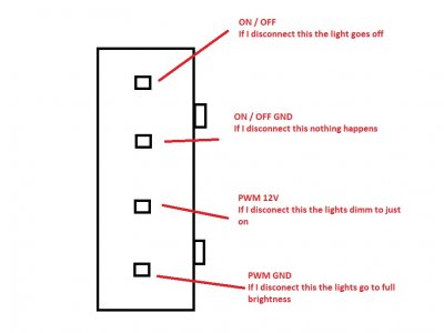
Ok just a quick update on control of the Viparspectra black box lights. I Found that inside the power box is as previously said is a 4 pin socket (see pic) for pin lay out. It turns out that if you link the 12V on and the on/ off Gnd the unit powers up. So I have tested this using an SSR run from the equipment timer of the reef pi program. I also made the voltage amplifier the Ranjib posted and supplied it via a voltage regulator 12V > 10V . I connected the PWM pin 1 from my servo control board and ran a test. and I'm happy to say it's working.
The only problem I found is if I set it to 0% intensity it goes to full brightness, this was the same as unplugging the PWM ground on my wire test yesterday. So the only way I can see of actually shutting the light off is to use a relay and set the times from that. this will mean I will have 4 wires for each channel or 8 wires in total per lighting unit. Granted they are low current so can be light weight like a lan (J45) cable and plugs.
This is a crude video just to help with my findings

LED power supply pin layout.jpg


I did a post from page 158 on wards I think on how I got my Spectras to work. I will hopefully be fitting all the sockets and final wirring to them this weekend all being well. I will post a link here to how and what I did in this thread but probably actually post it in a DIY thread thats already going for the Viparspectra light on the forum. so that it dosen't hijack the reef pi topic to much.
 
OP
OP
Ranjib

Ranjib

7500 Club Member
View Badges
Joined
Apr 16, 2016
Messages
9,847
Reaction score
17,077
Location
Pleasant Hill, Concord
Rating - 0%
0   0   0
Leak Detectors!!! The reason I stopped trying to code this project is my 200 gallon cracked at the bottom spilling water everywhere 4 months ago. Ever since then i have feared the worst of what would happen if one of my other tanks leaked anywhere while i was at work. I have other things to email when stuff goes out of spec, temperature, ph, orp, but the thing that keeps my 200 gallon empty still is the fear of the leak, plus the high cost of wifi leak detectors at $50 a pop.

Well i believe i now have found cheap leak detectors, and coded them up to email me when they detect even the smallest amount of water. Here they are, so simple to wire, only 3.3 vcc line, ground, and a data pin. I placed 5 around my tank, and tested all individually in a 1/4 cup of water, and then wipped them clean. Read accurately through the whole process. The only complaints on amazon are the probes rust. Well ours shouldn't because unlike plants ours, are supposed to be kept in a dry environment. And if one does rust, at $2 a pop, i won't care.

https://www.amazon.com/gp/product/B00ZR3B60I/ref=oh_aui_detailpage_o07_s00?ie=UTF8&psc=1

Hope this helps, and can be coded in to reef pi soon. Cheers!!!

Now that this is working im investigating 12v solenoids to shut down water flow areas when leaks are detected at different spots in the tank.

Yup this is something reef-pi needs to have first class support for.
One thing I want to point out in the meantime though, you can use the ATO module as leak detector. The ato module does not relay on hardware specificities, and will work with anything that will give a digital (on/off) signal. This include all sorts of float switches, mechanical switches and photoelectric water level sensors, leak detectors etc. One can configure the reef-pi's ato module to monitor at every minute interval and fireoff alert at 60 (60 second ), this will fire the alert soon when leak detector trips
 

lazybones51

New Member
View Badges
Joined
Feb 13, 2018
Messages
13
Reaction score
10
Rating - 0%
0   0   0
Schematic of dosing module electronics:

Theoretically, this is very similar to LED controller. i.e. we generate 5 volt pwm, and then boost it to 12v to power dosing pumps. Couple of main differences here is
1) I am using Pi zero hardware timer straight , instead of pca9685 chip to generate 5 v pwm. This is not a necessary step, if anyone has pca9685, they can use it instead as well.
2) I am using l293d , a dual bridge darlignton transistor IC to covert 5v pwm to 12v. This is necessary. Unlike kessil lights control signals, dosing pumps draw a lot of power. This particular IC support thats (600ma) . Apart from that, this IC also provide directional controls (forward or reverse) and has two outputs (can control both dosing pumps for my two part dosing regimen). These are very popular dc motor drivers,
Screen Shot 2018-02-11 at 2.14.45 AM.png
I've been following this thread for a few months and though it was about time I signed up and commented. The work you're doing Ranjib is great, thank you for sharing this project with the community :)

I had a question about the quoted post where you mention using the RPI PWM output instead of the pca9685, except in the context of being an LED controller and not dosing pumps. I've got a Meanwell power supply (PWM-60-12) which takes a 10v PWM signal for dimming, so i'd like to recreate what you've done except with 10v instead of 12v. Would you be able to share what you've done to use the RPI PWM instead of pca9685 please, i'm relatively new to electronics so all your help is appreciated.

I am however a software engineer so the coding/linux side of things isn't a problem at all :)
 
OP
OP
Ranjib

Ranjib

7500 Club Member
View Badges
Joined
Apr 16, 2016
Messages
9,847
Reaction score
17,077
Location
Pleasant Hill, Concord
Rating - 0%
0   0   0
I've been following this thread for a few months and though it was about time I signed up and commented. The work you're doing Ranjib is great, thank you for sharing this project with the community :)

I had a question about the quoted post where you mention using the RPI PWM output instead of the pca9685, except in the context of being an LED controller and not dosing pumps. I've got a Meanwell power supply (PWM-60-12) which takes a 10v PWM signal for dimming, so i'd like to recreate what you've done except with 10v instead of 12v. Would you be able to share what you've done to use the RPI PWM instead of pca9685 please, i'm relatively new to electronics so all your help is appreciated.

I am however a software engineer so the coding/linux side of things isn't a problem at all :)
Sure,
The electronics is similar to Kessil controller[1] , except instead of PCA9685 board, Raspberry Pi's GPIO 18 & 19 is used as 5 v pwm source. Which is then converted to 10v pwm using a common npn transistor (check the guide for schematics). There is not other changes in hardware. On the software side, Raspberry Pi pwm module has to be enabled[2] and reef-pi needs to be informed about using RPi pwm instead of pca9685. I am still working on the last bit, i.e. providing reef-pi UI for declaring pwm outputs as either RPi backed or pca9685 backed,

Let me know where you are in your build process. Would love to see some build pics :)

[1] Kessil controller guide: https://reef-pi.github.io/build-guides/lighting/
[2] RPi hardwarw pwm: http://www.jumpnowtek.com/rpi/Using-the-Raspberry-Pi-Hardware-PWM-timers.html
 
OP
OP
Ranjib

Ranjib

7500 Club Member
View Badges
Joined
Apr 16, 2016
Messages
9,847
Reaction score
17,077
Location
Pleasant Hill, Concord
Rating - 0%
0   0   0
I've been following this thread for a few months and though it was about time I signed up and commented. The work you're doing Ranjib is great, thank you for sharing this project with the community :)

I had a question about the quoted post where you mention using the RPI PWM output instead of the pca9685, except in the context of being an LED controller and not dosing pumps. I've got a Meanwell power supply (PWM-60-12) which takes a 10v PWM signal for dimming, so i'd like to recreate what you've done except with 10v instead of 12v. Would you be able to share what you've done to use the RPI PWM instead of pca9685 please, i'm relatively new to electronics so all your help is appreciated.

I am however a software engineer so the coding/linux side of things isn't a problem at all :)
Welcome to r2r :) , as well
 

TheHarold

5000 Club Member
View Badges
Joined
Oct 3, 2015
Messages
5,148
Reaction score
8,760
Rating - 0%
0   0   0
Welcome to r2r :) , as well

Is there already a STL file for a housing? Ive been following, on the line of ordering the hardware but it most definitely needs an enclosure. I have a 3D printer so it should be easy enough.
 
Back
Top