reef-pi :: An opensource reef tank controller based on Raspberry Pi.

So, I'm having an issue with telemetry. Reef-Pi 2.0 on Pi0.

When I put the AIO key in and hit "update" it gives me an error and says "please set a valid password".

Email alerts aren't enabled.

The log says "Invalid API key provided"
Can be a software bug, let me test this out and get back to you
 
Can be a software bug, let me test this out and get back to you
Its a bug :-( . https://github.com/reef-pi/reef-pi/issues/651 , I'll fix it soon.
Meanwhile, you should be able to save the telemetry config by adding bogus (non-empty) values in username/password section of email setting, just keep it disabled and reef-pi wont send any email.
 
currently, the calibration features only allow speed (percentage of a single PWM channel) and duration.
what would it take to get steps (number of pulses per ml) in the program? control multiple dosers? and each pump would need its own calibration cause of viscosity of different fluids.
 
Its a bug :-( . https://github.com/reef-pi/reef-pi/issues/651 , I'll fix it soon.
Meanwhile, you should be able to save the telemetry config by adding bogus (non-empty) values in username/password section of email setting, just keep it disabled and reef-pi wont send any email.
Ok, any ideas why it's not sending the data to adafruit though ?
 
Nope. Nothing
So,let me reiterate how this circuit works ,
Guys, I took my DCI apart today and here are images. I ran the multimeter across them to verify resistance and r3 was 2.66k ohm. Rest are readable in the images. Lmk if this tells you guys anything about what we passed thru to the jebao wp pumps from the 0-10v analog signal.
e4d4e799d0660752e1a2b960c2b31aa6.jpg
831a3fbca85724e4ba46b5261ea9c3bb.jpg
I think I get it. It’s simple voltage divider to convert 10v to 5v and then there’s the 24v power source. Dor proto type you’ll be using pca9685 or pi as pwm source ? Do you have 24v power supply ? And 3pin connector to play with ?
 
Ok, any ideas why it's not sending the data to adafruit though ?
It should send data adafruit . Mine is working fine. When you refresh your configuration / telemetry section , do you see telemetry checked ? Or it’s unchecked?
 
what would it take to get steps (number of pulses per ml) in the program? control multiple dosers? and each pump would need its own calibration cause of viscosity of different fluids.
I have to read through the stepper documentation to answer this. I had remembered this , but forgot. Once we figure out how to do one channel, supporting multiple pump is not an issue , as it’s just replicating the same thing across multiple channels. If we are lucky we should be able to get away with something like l293d or we may need dedicated stepper driver that will take pwm and control nema17 stepper motors
 
Ok, any ideas why it's not sending the data to adafruit though ?
Also, does the log says anything? Do you see anything under the errors section in configuration ?
 
I have to read through the stepper documentation to answer this. I had remembered this , but forgot. Once we figure out how to do one channel, supporting multiple pump is not an issue , as it’s just replicating the same thing across multiple channels. If we are lucky we should be able to get away with something like l293d or we may need dedicated stepper driver that will take pwm and control nema17 stepper motors

If it’s just motors, we will need stepper drivers. Most of the good TI ones or variants have a few settings pins (can be hard wired, but controls microsteps etc), a direction pin, and a step input pin where a PWM can go.
 
I have to read through the stepper documentation to answer this. I had remembered this , but forgot. Once we figure out how to do one channel, supporting multiple pump is not an issue , as it’s just replicating the same thing across multiple channels. If we are lucky we should be able to get away with something like l293d or we may need dedicated stepper driver that will take pwm and control nema17 stepper motors

If you can I set the number of pulses on a pin its really easy. I just dont know the programming. its 3 wires on the pi 2 can be used for all pumps, and the 3rd is unique per pump. so wires needed for a stepper is x+2. where is number of pumps. I'm building a board with all this built in and will be hardwired to max microstepping. which is as simple as bonding the 3.3volt to where pins 14,15,and 18 go on the driver. wont need a reverse so pin 20 isnt needed. so 3.3 volts for all dosing pumps and ground for all. then just the step pin for each individual pump pin moves 1 step per pulse on the pin its connected to. so 4 dosing pumps piwould use say the 3.3v pin and a ground and then 2,3,4,17 for the step input. but the board im designing is also gonna have relays that can run off 14,15,18,23 while using the same 3.3v pin and grounds. I have transistors and running it off 12 volts since thats what is needed for the stepper motors. also might use a voltage regulator and transistor to make the 3.3 volt rail stronger. (more current (ma)) so I dont burn the pi out. Below is a picture showing how to connect a stepper to a pi. but they have it adjustable microsteps by enableing and disabling pins 14,15,18 and it uses pin 20 for either clockwise or counter clockwise when set high, and the reverse direction when set low. Im just gonna tie it to either high or low once I see which way is spins the pump. all steppers spin the same when connected to the stepper driver so once I figure it out for 1 I can make all them the same and then order the circuit boards I've designed. currently set for 4 pumps and 4 relays, thinking about getting a pca9685 and seeing if I can get that to work once I get the basics to work. if I can Ill design it around an 8 and 8 setup with the chip built in so its only a few wires from the pi to the control center. I just dont know how to control the programming of the pi to control the steppers. and if I did i couldnt put it in your program. Hope Im not over bearing.
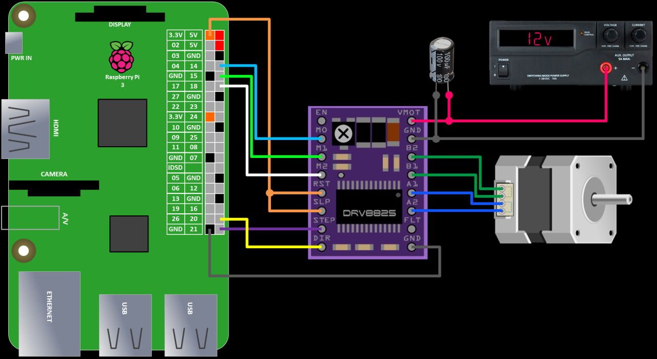






PiStepper03.png
 
It should send data adafruit . Mine is working fine. When you refresh your configuration / telemetry section , do you see telemetry checked ? Or it’s unchecked?

Yep it's checked, but the AIO key is always blank even after I add it.

Also, does the log says anything? Do you see anything under the errors section in configuration ?

I think it's saying "invalid API key"
 
Yep it's checked, but the AIO key is always blank even after I add it.


I think it's saying "invalid API key"
I just tested this, I was able to update both AIO token as well as usrname and save it (has to add some fake data in email details, but kept it disabled at the end, just to workaround with the validation bug). Remember you have to reload reef-pi anytime you change telemetry or settings
 
If you can I set the number of pulses on a pin its really easy. I just dont know the programming. its 3 wires on the pi 2 can be used for all pumps, and the 3rd is unique per pump. so wires needed for a stepper is x+2. where is number of pumps. I'm building a board with all this built in and will be hardwired to max microstepping. which is as simple as bonding the 3.3volt to where pins 14,15,and 18 go on the driver. wont need a reverse so pin 20 isnt needed. so 3.3 volts for all dosing pumps and ground for all. then just the step pin for each individual pump pin moves 1 step per pulse on the pin its connected to. so 4 dosing pumps piwould use say the 3.3v pin and a ground and then 2,3,4,17 for the step input. but the board im designing is also gonna have relays that can run off 14,15,18,23 while using the same 3.3v pin and grounds. I have transistors and running it off 12 volts since thats what is needed for the stepper motors. also might use a voltage regulator and transistor to make the 3.3 volt rail stronger. (more current (ma)) so I dont burn the pi out. Below is a picture showing how to connect a stepper to a pi. but they have it adjustable microsteps by enableing and disabling pins 14,15,18 and it uses pin 20 for either clockwise or counter clockwise when set high, and the reverse direction when set low. Im just gonna tie it to either high or low once I see which way is spins the pump. all steppers spin the same when connected to the stepper driver so once I figure it out for 1 I can make all them the same and then order the circuit boards I've designed. currently set for 4 pumps and 4 relays, thinking about getting a pca9685 and seeing if I can get that to work once I get the basics to work. if I can Ill design it around an 8 and 8 setup with the chip built in so its only a few wires from the pi to the control center. I just dont know how to control the programming of the pi to control the steppers. and if I did i couldnt put it in your program. Hope Im not over bearing.



PiStepper03.png

I recommend also connecting the enable pin to the Pi. Stepper drivers will hold their position actively when not given any step signals (this is normally what you want if you use steppers for motion control), but you're burning a lot of power in the motor, and the pump doesn't require holding position for the majority of the time. You can probably just use one enable line, and enable the pumps as a bank, to conserve GPIO.
 
I just tested this, I was able to update both AIO token as well as usrname and save it (has to add some fake data in email details, but kept it disabled at the end, just to workaround with the validation bug). Remember you have to reload reef-pi anytime you change telemetry or settings

Maybe I wasn't hitting the reload, it's working now!

Any ideas why when I change the wifi network reef pi won't show up in the browser? The service is running but the browser just says it couldn't contact the host. Is this a cache issue?
 
Maybe I wasn't hitting the reload, it's working now!

Any ideas why when I change the wifi network reef pi won't show up in the browser? The service is running but the browser just says it couldn't contact the host. Is this a cache issue?
Raspbian by default uses DHCP, so the ip address will possibly change every time you change networks or reboot. Use the ipconfig command in a terminal to find the current address and then you can access with the current address. You can change to a static ip and it will always stay that address or set up your host name and use that to "talk" to it.
 
Maybe I wasn't hitting the reload, it's working now!

Any ideas why when I change the wifi network reef pi won't show up in the browser? The service is running but the browser just says it couldn't contact the host. Is this a cache issue?
Likely a cache issue. But to confirm, I need the exact steps to reproduce it. Once I am able to reproduce it, I can tell you with confidence the exact cause
 
Raspbian by default uses DHCP, so the ip address will possibly change every time you change networks or reboot. Use the ipconfig command in a terminal to find the current address and then you can access with the current address. You can change to a static ip and it will always stay that address or set up your host name and use that to "talk" to it.
I generally update the hostname (using raspi-config , as mentioned in the install guide), and then access my reef-pi with their hostname directly, like: http://kessil.local (hostname set here is 'kessil')
 
Guys, I took my DCI apart today and here are images. I ran the multimeter across them to verify resistance and r3 was 2.66k ohm. Rest are readable in the images. Lmk if this tells you guys anything about what we passed thru to the jebao wp pumps from the 0-10v analog signal.
e4d4e799d0660752e1a2b960c2b31aa6.jpg
831a3fbca85724e4ba46b5261ea9c3bb.jpg
Is this what I think it is? A DA ReefKeeper DCI?

Correct me if I am wrong but DCi module works with the APC module.

DCI control the power source of the pump but I think the APC module is the one controlling the signal to the pump.

If you figure out how to make it work with pi, please share. I have Jebao PP8 pump that I need control over. I will look at my RKM-APC/DCI module to see what s in there.

I am kind of done with messing around with DA module though. I fried my pi. It wont boot anymore. :-(
 
So,let me reiterate how this circuit works ,

I think I get it. It’s simple voltage divider to convert 10v to 5v and then there’s the 24v power source. Dor proto type you’ll be using pca9685 or pi as pwm source ? Do you have 24v power supply ? And 3pin connector to play with ?

Pca9685 as the 5v source. Yes I have the 24v supply and verified it works and also the three pin. Do t think I'm getting a 5v source from the pca9685.
 
Back
Top
Home
Post thread…
Market
What's new






