reef-pi :: An opensource reef tank controller based on Raspberry Pi.

ColoredRock

Well-Known Member
View Badges
Joined
Aug 9, 2021
Messages
856
Reaction score
976
Location
Murrieta, CA (North of San Diego)
Rating - 0%
0   0   0
Finally decided to try to build a reef-pi as a fun project. Is there an updated shopping list anywhere? I want to make sure I get the correct pile of basic parts since the budget pack listed on adafruit is out of stock. Thanks!
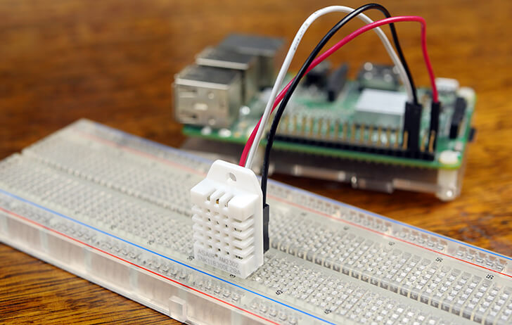
You can use that basic parts list and get them from amazon etc.. pi's are still hard to come by but they are slowly comng back into the supply chain.. you can also look @ robotank.ca who has a good pre built hat. What is you want to do? Monitor temp and pH? Turn equipment on and off? So many different things you can do.


scottsmith

New Member
View Badges
Joined
Jul 21, 2021
Messages
4
Reaction score
7
Location
Australia
Rating - 0%
0   0   0
Hi all,
Finally got my controller brain assembled, loving the recent work by the dev team.

I’ve seen some threads about alternate/updated UIs featuring dark mode styling and nicer graphs, but nothing concrete. Does anyone know if there is any work going on here or should I fork the repo and get cracking myself?
A33422AD-8337-403B-94C5-1493D517A5CF.jpeg
 

Attachments

  • C8868810-A5C7-4562-AA0A-A37119549C59.jpeg
    C8868810-A5C7-4562-AA0A-A37119549C59.jpeg
    262.7 KB · Views: 98
OP
OP
Ranjib

Ranjib

7500 Club Member
View Badges
Joined
Apr 16, 2016
Messages
9,876
Reaction score
16,680
Location
Pleasant Hill, Concord
Rating - 0%
0   0   0
Hi all,
Finally got my controller brain assembled, loving the recent work by the dev team.

I’ve seen some threads about alternate/updated UIs featuring dark mode styling and nicer graphs, but nothing concrete. Does anyone know if there is any work going on here or should I fork the repo and get cracking myself?
A33422AD-8337-403B-94C5-1493D517A5CF.jpeg
Get cracking yourself. If it’s reusable, send a pr.
thank you for sharing your build pics, it looks awesome
 

eggi55

Community Member
View Badges
Joined
Sep 18, 2022
Messages
63
Reaction score
50
Location
germany
Rating - 0%
0   0   0
Hello
I'm running reef-pi 6.0 and I have a problem with the dosing pumps, they run by themselves after a few days.
I currently only have one running to test.
Restarted the Raspi and everything went back to normal. This repeated itself after a few days, this time I tried my 6 channels and all were on.
My dosing pumps run via the PCA 9685. This time I disconnected the PCA from the Raspi with power supply and then everything worked again.
 

tfabio

New Member
View Badges
Joined
Mar 4, 2023
Messages
3
Reaction score
1
Location
Uk
Rating - 0%
0   0   0
Hi, new to the forum and I have an issue setting up a Leviathan board 1.0, I hope I can get some help in this thread :)

Basically, I can't get the raspberry pi powered by Leviathan board:
  • Rasberry Pi works fine (with Levianthan image) when powered via usb
  • I can read 5V at the connector that go onto the Levianthan from the buck board.
  • Reading other posts and the doc, it seems I should read 5V at the pin 2 and 6 - I don't get this reading. To be sure I am using the right pins (never used the GPIO of the raspberry pi), I attached a photo of the pins I a testing.
Any idea about what could be the problem?


Sral

Valuable Member
View Badges
Joined
May 2, 2022
Messages
1,015
Reaction score
943
Location
Germany
Rating - 0%
0   0   0
Hi, new to the forum and I have an issue setting up a Leviathan board 1.0, I hope I can get some help in this thread :)

Basically, I can't get the raspberry pi powered by Leviathan board:
  • Rasberry Pi works fine (with Levianthan image) when powered via usb
  • I can read 5V at the connector that go onto the Levianthan from the buck board.
  • Reading other posts and the doc, it seems I should read 5V at the pin 2 and 6 - I don't get this reading. To be sure I am using the right pins (never used the GPIO of the raspberry pi), I attached a photo of the pins I a testing.
Any idea about what could be the problem?


Hi and welcome aboard !

A link to the documentation would be useful, since the one I can find online on leviathanautomation.com for the 1.1 version looks different.

Can you provide well lighted screenshots of front and back, so we might be able to trace the connections on the board ?

My guess might be that you are not actually contacting the header contacts inside with these two cables. Try using two male header pins instead.

Another wild guess is that the header could be connected two ways, turned by 180 degrees each. Maybe you measure the wrong side or inserted the Pi incorrectly turned ?

I would be careful about testing the latter, since inserting the PI the wrong way might damage something.
 
Last edited:

tfabio

New Member
View Badges
Joined
Mar 4, 2023
Messages
3
Reaction score
1
Location
Uk
Rating - 0%
0   0   0
Hi and welcome aboard !

A link to the documentation would be useful, since the one I can find online on leviathanautomation.com for the 1.1 version looks different.

Can you provide well lighted screenshots of front and back, so we might be able to trace the connections on the board ?

My guess might be that you are not actually contacting the header contacts inside with these two cables. Try using two male header pins instead.

Another wild guess is that the header could be connected two ways, turned by 180 degrees each. Maybe you measure the wrong side or inserted the Pi incorrectly turned ?

I would be careful about testing the latter, since inserting the PI the wrong way might damage something.

Hey Sral,

Thanks for your help. Here is the link to the 1.0 version: https://docs.google.com/document/d/...ouid=116765926172589627234&rtpof=true&sd=true
Attached more pictures.

I did further measurements:
1) with the Pi connected to the USB power - I measure 5V (see photo) at the 1 and 6 GPIO as it should be https://s3.amazonaws.com/youngwonks/Blogs/GPIO_diagram.jpg (see photo)
2) with the Pi connected to the USB power - I measure 5V (see photo) in the 5V connector in the Leviathan board

so it looks like the connections between the PI and Leviathan board are alright.
Something seems somewhere between the power supply and the 5V connector in the Leviathan board, but I don't get what as I measure 5V in output of the buck converter (measured directly on the female JST connector)

I measured the 1-6 pin with
 

Attachments

  • PXL_20230304_141248821.jpg
    PXL_20230304_141248821.jpg
    189.3 KB · Views: 74
  • PXL_20230304_141224868.jpg
    PXL_20230304_141224868.jpg
    193.2 KB · Views: 78
  • PXL_20230304_141129500.jpg
    PXL_20230304_141129500.jpg
    251.7 KB · Views: 64
  • PXL_20230304_141210855.jpg
    PXL_20230304_141210855.jpg
    209.2 KB · Views: 69
  • PXL_20230304_143355358.jpg
    PXL_20230304_143355358.jpg
    179.2 KB · Views: 65
  • PXL_20230304_144045584.jpg
    PXL_20230304_144045584.jpg
    153.3 KB · Views: 78

tfabio

New Member
View Badges
Joined
Mar 4, 2023
Messages
3
Reaction score
1
Location
Uk
Rating - 0%
0   0   0
Posted in the FB group too and Brandon spotted the issue: I used already wired JST cable and they can be fitted only on one way. I didn't notice that the way the connectors were supposed to be fitted was on the other way around of what the Leviathan board was expecting. Basically, I connected the V+ to the V-.... and fried up the PI.

Thanks Sral for the help.
 

Sral

Valuable Member
View Badges
Joined
May 2, 2022
Messages
1,015
Reaction score
943
Location
Germany
Rating - 0%
0   0   0
Posted in the FB group too and Brandon spotted the issue: I used already wired JST cable and they can be fitted only on one way. I didn't notice that the way the connectors were supposed to be fitted was on the other way around of what the Leviathan board was expecting. Basically, I connected the V+ to the V-.... and fried up the PI.

Thanks Sral for the help.
Sry to hear that, I just spotted the same thing :crying-face:
 

Sral

Valuable Member
View Badges
Joined
May 2, 2022
Messages
1,015
Reaction score
943
Location
Germany
Rating - 0%
0   0   0
Guess that's a good lesson for everybody who wants to make these kind of boards: try including a simple reverse polarity circuit made with a p-MOSFET, if you can find the space. Cost of the MOSFET: likely a few cents vs the cost for a fried Raspberry Pi, where I don't want to guess the amount of time, money and swearing involved right now.
 

Dom

Theoretical Reef Keeper
View Badges
Joined
Apr 29, 2016
Messages
7,755
Reaction score
8,191
Location
NY
Rating - 0%
0   0   0
Hmmm... okay... I have a raspberry pi... now I know what I'm going to do with it...
 

Dave's Reef

Active Member
View Badges
Joined
Nov 4, 2018
Messages
102
Reaction score
148
Rating - 0%
0   0   0
Hi everyone. I have been updating my reef-pi and wanted to use an esp32 to monitor a hand full of level switches. Is there a tutorial out there on setting the esp32 up with reef-pi? I've searched for day with no luck. Thank for any help you can provide.
 

Sral

Valuable Member
View Badges
Joined
May 2, 2022
Messages
1,015
Reaction score
943
Location
Germany
Rating - 0%
0   0   0
Hi everyone. I have been updating my reef-pi and wanted to use an esp32 to monitor a hand full of level switches. Is there a tutorial out there on setting the esp32 up with reef-pi? I've searched for day with no luck. Thank for any help you can provide.
I have made a preliminary one in this thread

One thing to watch out for: the ESP32 board currently reboots every 5-10 minutes which causes sensors to read as „0“ if you ask their status during these instances. Reboot is very quick and a matter of seconds though. I’m currently working on a solution.
 

Dave's Reef

Active Member
View Badges
Joined
Nov 4, 2018
Messages
102
Reaction score
148
Rating - 0%
0   0   0
I have made a preliminary one in this thread

One thing to watch out for: the ESP32 board currently reboots every 5-10 minutes which causes sensors to read as „0“ if you ask their status during these instances. Reboot is very quick and a matter of seconds though. I’m currently working on a solution.
Thank you ill will be giving this a go over next weekend
 

Simonv92

Active Member
View Badges
Joined
Oct 21, 2014
Messages
161
Reaction score
104
Location
Italy
Rating - 0%
0   0   0
I think I've found a bug in v 6.0... If I disconnect any DS18B20 probe while the controller is power on I read -1°C which kicks ON my heater as my threshold is set to 23°C...
I think this is pretty dangerous as any sensor fault will turn on the heater (or anything else)...
There's a way to disable the temperature controller if the sensor goes bad?

edit:
I think we can achieve some kind of protection using 2 sensors:
- Sensor 1 is the main sensor which controls heater and chiller (and alerts)
- Sensor 2 will run a macro to disable sensor 1 if he reads value outside of the alerts range

What do you think? Have you implemented some kind of redundancy?
 
Last edited:

Simonv92

Active Member
View Badges
Joined
Oct 21, 2014
Messages
161
Reaction score
104
Location
Italy
Rating - 0%
0   0   0
Thanks for the kind words, working on bringing back that GUI. :) For the DHT22 you can run a python script like this, if you edit it so only the humidity is saved to the file you can import it in reef-pi using the file driver. If you can get away from I2C its best, I know it's tempting though with 2 wires vs 16.

Hi @robsworld78, can you please help in the step to add DHT22 sensor in Reef-Pi? I've done some test but I can only see the values in the command line... Thank you!
 

Sral

Valuable Member
View Badges
Joined
May 2, 2022
Messages
1,015
Reaction score
943
Location
Germany
Rating - 0%
0   0   0
I think I've found a bug in v 6.0... If I disconnect any DS18B20 probe while the controller is power on I read -1°C which kicks ON my heater as my threshold is set to 23°C...
I think this is pretty dangerous as any sensor fault will turn on the heater (or anything else)...
There's a way to disable the temperature controller if the sensor goes bad?

edit:
I think we can achieve some kind of protection using 2 sensors:
- Sensor 1 is the main sensor which controls heater and chiller (and alerts)
- Sensor 2 will run a macro to disable sensor 1 if he reads value outside of the alerts range

What do you think? Have you implemented some kind of redundancy?
I have suggested the same thing for sensors in general, e.g. an „error mode“ where values are disregarded and maybe even hand control over to a backup. For pH and Temperature these are the obvious error values of 0 and -1 (or -127 for the DS18B20 on the ESP32, if I remember correctly).
Alternatively one could let the user decide for an allowed range of values.

It’s definitely on @Ranjib‘s list.
 

robsworld78

Valuable Member
View Badges
Joined
Feb 14, 2020
Messages
1,029
Reaction score
1,293
Location
Edmonton, Canada
Rating - 0%
0   0   0
Hi @robsworld78, can you please help in the step to add DHT22 sensor in Reef-Pi? I've done some test but I can only see the values in the command line... Thank you!
Hi Simon, if you have data in the terminal then it should just be a matter of splitting up the data in it's own CSV file. Here's the code from that link tweaked a bit, untested but should work. You'll have to change the pin number.

In reef-pi when you add the "analog-file" driver use these paths to read the temperature and humidity, you need to setup a driver for each if you want to see both. After you add the drivers then add an analog connector for both and remember to go to the admin tab and press the "reload" button after. Then you should be able to add them to the pH tab.

/var/lib/reef-pi/dht22/temperature.txt

/var/lib/reef-pi/dht22/humidity.txt


Python:
import os
import time
import Adafruit_DHT

DHT_SENSOR = Adafruit_DHT.DHT22
DHT_PIN = 4

try:
    f = open('/var/lib/reef-pi/dht22/temperature.txt', 'w')
    f.write('Temperature\r\n')

    f = open('/var/lib/reef-pi/dht22/humidity.txt', 'w')
    f.write('Humidity\r\n')
except:
    pass

while True:
    humidity, temperature = Adafruit_DHT.read_retry(DHT_SENSOR, DHT_PIN)

    if humidity is not None and temperature is not None:
        f.write('{0},{1},{2:0.1f}*C,{3:0.1f}%\r\n'.format(time.strftime('%m/%d/%y'), time.strftime('%H:%M'), temperature, humidity))
    else:
        print("Failed to retrieve data from humidity sensor")

    time.sleep(30)
 

TOP 10 Trending Threads

WHAT AMOUNT OF LIVE ROCK AND SAND SHOULD BE PRIORITIZED FOR OPTIMAL BIODIVERSITY/FILTRATION?

  • 100% live rock + bagged sand

    Votes: 37 27.4%
  • 100% dry rock + 100% live sand

    Votes: 46 34.1%
  • 50/50 live/dry rock, 50/50 live/bagged sand

    Votes: 30 22.2%
  • 75% live rock, 25% live sand

    Votes: 12 8.9%
  • 25% live rock, 75% live sand

    Votes: 10 7.4%
Back
Top