Adding a ramp timer

OP
OP
jsmkmavity

jsmkmavity

Valuable Member
View Badges
Joined
Apr 21, 2023
Messages
2,487
Reaction score
3,943
Location
Sandpoint
Rating - 0%
0   0   0
Thank you everyone for your help i appreciate the time you are investing.
 

DanyL

Valuable Member
View Badges
Joined
Jan 13, 2023
Messages
2,233
Reaction score
2,440
Location
Middle East
Rating - 0%
0   0   0
So the microcontroller needs reprogrammed or replaced so i can access/control it?
It depends on the path one would go with.
You can either reprogram the current microcontroller and replace the whole logic, add another one to add only the ramping logic, or outright replace it like Oreo suggested.


I would send the controller or other parts to someone if they wanted to play with it. If there is one already setup to program i can access i would buy it. I dont mind sending this out but i would rather learn how to do it myself with help from people who know how and what i need. I have let technology pass me by so long i think it’s about to put me a(nother) lap down!!!
Shipping it to me probably isn’t worth it, since I’m on the other side of the world and the shipping cost would likely be more than the fixture itself.


To be honest, outside of Oreo’s idea of just replacing the whole board (which still takes some learning, but is fairly direct), the solution I suggested, adding a microcontroller in-line to intercept and modify the signals or reimplementing the whole logic and replacing the current firmware, are probably a bit out of reach for you right now.

It’s a clean and elegant approach, and not super complex for someone with a bit of tinkering experience. But it does involve working across both hardware and software, and some general understanding of how things work under the hood.

I assumed you already had some of that base knowledge, enough to fill in the gaps as we go. But it sounds like you’re starting from scratch, and without internet access on your computer, even getting the basic tools and drivers installed becomes a blocker.

If you’re genuinely interested in learning, I’d still suggest picking up something like an Arduino and starting with small projects. There’s a ton of resources out there, and it’s the best way for you to build up the skills you’ll need to take on something like this later on.
 
Last edited:

oreo54

5000 Club Member
View Badges
Joined
Sep 18, 2017
Messages
6,896
Reaction score
4,093
Rating - 0%
0   0   0
I would send the controller or other parts to someone if they wanted to play with it. If there is one already setup to program i can access i would buy it. I dont mind sending this out but i would rather learn how to do it myself with help from people who know how and what i need. I have let technology pass me by so long i think its about to put me a(nother) lap down!!!


Thanks for the full light shot. Unfortunately it really didn't help much. I can't believe the amount of senseless wire color changes and excess wiring. Looks like something I'd build.. NOT a compliment.
 
OP
OP
jsmkmavity

jsmkmavity

Valuable Member
View Badges
Joined
Apr 21, 2023
Messages
2,487
Reaction score
3,943
Location
Sandpoint
Rating - 0%
0   0   0
@oreo54
So should i order a new board? And which one? The tc420, or is there a bluetooth option? My dad is computer savvy and he could help with the online/software or whatever stuff. Where do you order parts like this?
 

oreo54

5000 Club Member
View Badges
Joined
Sep 18, 2017
Messages
6,896
Reaction score
4,093
Rating - 0%
0   0   0
@oreo54
So should i order a new board? And which one? The tc420, or is there a bluetooth option? My dad is computer savvy and he could help with the online/software or whatever stuff. Where do you order parts like this?
Honesty, I feel that "I" don't know enough about 1) Exactly how that light works and 2) definitely do not know microcontrollers nor any programming.

My original idea of course was to remove the controller from the question.
After all led lights are just power/driver/ led.

If "we" knew how and where the dim signal was used it is just a matter of replicating it with a different tinker toy .

But even your drivers are odd.. too many wires.
The one connector is labelled vr1, pwm, gnd.
Vr1 as I understand it stands for variable resistor 1. Pwm gnd are obvious.
I have no idea why vr is there except to assume it has something to do with the pot dimming.
The 2 other sets of wires are obvious. Ac in to driver and DC out to led.

I'd attack the pwm wire..but without knowing " exactly" the characteristics of the signal using it is a shot in the dark.
From the esp chip basic outputs it is " likely" to use either a 3.3 or 5v pwm signal running between 100-1000Hz.
Now what the driver wants is ?

So the first logical thing would be to prove the microcontroller outputs ( white/ grey wire) and its voltage inputs. You know one .the 3.3v pin.
The other voltage feed to it is ?. My guess is , since it looks like the light only switches the OEM source to driver both voltage sources should be " live" with the light switched on regardless of which pwm source was selected ( wifi switch).

And an added mystery...WHERE do those voltages come from? There needs to be a source. My guess is the 12v board ( which also runs the fans) has some other voltage regulator ics on it supplying the 3.3v and ? Voltage to the esp board.

Now for the sad part. "If" the wifi state is LEDs off there is no way to understand what the microcontrollers pwm IS. It would need to be at 100% Then one could get voltage and possibly the frequency ( Hz).
Of course getting the frequency involves using an oscilloscope..

I could go on but you may start to see that it's impossible to suggests " parts" at this stage.

Now IF I cared to " play" and pray I'd conduct one simple experiment to prove that I at least understand the basics

Starting with buying a cheap vom if you don't have one and one manual strip dimmer.
Screenshot_20250411-111108.png


These are dirt cheap and internally " should" have what you need...a 5v pwm output to test the driver.

These can be powered from at least 9 to 24v DC.
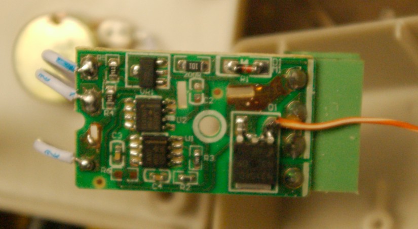
Internally there is like a 555 timing chip (or similar) and a mosfet. You will want to solder a wire to the gate of the mosfet.
Orange wire in this pic:
hack.JPG


This is your own " probe" wire. No guarantee but historically it's 5v 490Hz ( approx)
The "in" is where you power the dimmer circuit.. Like I said anywhere around 9-24v. "OUT" will not be used.
Current draw is minimal.


Now you can power this " probe" off your light in a few ways .1) tapping the 12v fan circuit or 2) use your vom and see what that other voltage is on the microcontroller. If greater than 5v you can use that.
Btw i'd disconnect ALL the wires from the microcontroller noting their positions for reattachment later if this fails.( Photos work)..That way you won't accidentally fry it.

Your target for that orange wire is the yellow wire on the driver.
I'd probably de-solder the 2 (1 per driver ) center wires off the switch where the microcontroller white/grey wires (converted to black/red). That should eventually go to the yellow wire BUT I can't tell from here. Use it as your access to the pwm yellow wire.Arrowed wires below "should" be to the yellow pwm on each driver.
pwmwire.jpg

driveryellowwire .jpg


Of course the led board needs to hooked up to the driver. Don't think you need to worry about the ground side of the driver if you use one of the power sources inside the light.

DISCLAIMER: This is a ll at your own risk. I have no guarantee this will work, or will not damage something. This is to the best of my limited knowledge here and obviously any of the work is out of my hands. This is more of a thought exercise than a "HOW TO" and should be treated as such.

Correction: I mistook the 3.3v to be a 3.3v "in" but it appears to be an "out". Looks to power the "manual" dimmer circuit board for the pots.
The vin should be between 5-10v
DC. Orange and brown wire. 5v will probably not run the manual dimmer.
 
Last edited:

Minifoot77

Jack of all trades and a master of none
View Badges
Joined
Jul 3, 2022
Messages
3,564
Reaction score
10,907
Location
Ottawa
Rating - 0%
0   0   0
I used vipar 165s and a Steve's led controller interface with my hydros control 4
 

oreo54

5000 Club Member
View Badges
Joined
Sep 18, 2017
Messages
6,896
Reaction score
4,093
Rating - 0%
0   0   0
GOING way back to trying to invoke its own internal network.. in that one video and actually with my esp32 boards after a power failure (unplugging) one needed to push the "reset" button in order to get it up and running again.

LAST try at getting a network up in your available network menu.

Put it together, plug it in, turn it on, set it to wifi, push the reset button (brief hold), check your phones available network for odd ones.

Time to edit my above big post expired. Thought I'd list an already possible failure point.
Pretty sure the yellow wire going to the driver would measure 3.3V at 100% output. All these cheap controllers usually are 5V on the mosfet gate.
IF the driver will accept 5v is ?

ALSO IF you wanted to start from scratch here the board:
Amazon product

For programming nerds this would be a piece of cake.. For us mortals.. forget it..

  • Arduino compatible, works great with the latest Arduino IDE/Mongoose IoT/Micropython
  • Data download access to the website: http://www;nodemcu;com
THIS one looks like fun..Probably wouldn't fit back in your case though.
Amazon product

ACTUALLY in your case might as well upgrade to the esp32 board. Has bluetooth.

Amazon product

How to Make ESP32-OLED Board Work:​


  • Refer to the 4th Picture and 5th picture above. Download the driver, connect board to the computer with Micro USB cable, configure the IDE, and upload the code to board
.
Sounds easy doesn't it...

All the instructions for hooking up the board to a pc are there as well. Partial below. Just find a Aduino coder. Probably could be done in a day.

esp32.jpg


To be honest.. the code (or modifiable code) is probably already out there..


All it is is scheduling 2 pwm channels..
 
Last edited:

oreo54

5000 Club Member
View Badges
Joined
Sep 18, 2017
Messages
6,896
Reaction score
4,093
Rating - 0%
0   0   0
DANG.. Can't edit the above post now..
Hey see if this person will build the new module..


Anyways sample code.
Screenshot 2025-04-11 150944.png
 
Last edited:
OP
OP
jsmkmavity

jsmkmavity

Valuable Member
View Badges
Joined
Apr 21, 2023
Messages
2,487
Reaction score
3,943
Location
Sandpoint
Rating - 0%
0   0   0
Ok, so now i realize a bit more info about me might have been helpful. I am a hvac technician (34 years), with a lot of electrical experience for 120/240 volt ac and 24 volt ac control wiring. I have good test meters. I can test for voltage wherever you want before i take things apart if that helps. If it just makes more sense to start over with esp32 and/or arduino that is fine too.
 

DanyL

Valuable Member
View Badges
Joined
Jan 13, 2023
Messages
2,233
Reaction score
2,440
Location
Middle East
Rating - 0%
0   0   0
I know you already said you only have a laptop without an internet connection, but but are you able to install something on it if we find a way to connect it to the internet, or transfer files to it in another way?
 
OP
OP
jsmkmavity

jsmkmavity

Valuable Member
View Badges
Joined
Apr 21, 2023
Messages
2,487
Reaction score
3,943
Location
Sandpoint
Rating - 0%
0   0   0
I could take it to my dad and he could download/install it
 

DanyL

Valuable Member
View Badges
Joined
Jan 13, 2023
Messages
2,233
Reaction score
2,440
Location
Middle East
Rating - 0%
0   0   0
OK.

This is esptool - this will allow you to read and write your microcontroller.

And this is the USB driver - which allows your computer to communicate with the onboard USB controller:

I’m tempted to suggest installing Arduino studio too, but I’m afraid you will end up needing internet connection again and again to be able to install libraries.
So that’s depends on you willingness to try and write some code yourself.

The end goal here is to the very least be able to to dump the firmware so others could potentially install it on their own board and debug it locally, or otherwise reverse engineer it directly, though not many are familiar enough with Xtansa ISA, and there aren’t any good disassemblers nor decompilers available for it.
 
OP
OP
jsmkmavity

jsmkmavity

Valuable Member
View Badges
Joined
Apr 21, 2023
Messages
2,487
Reaction score
3,943
Location
Sandpoint
Rating - 0%
0   0   0
I got on borneo and description sounds promising but i cant find anyplace there to buy it or where to buy it.
 

oreo54

5000 Club Member
View Badges
Joined
Sep 18, 2017
Messages
6,896
Reaction score
4,093
Rating - 0%
0   0   0
My honest opinion.. Dealing with the current controller and its firmware is pointless. Even if one manages to configure it with it being wifi sooner or later it will be annoying.

Only reasonable (not that others cant be done) is a complete replacement either like a tc-420 or a new esp32 board via bluetooth.

At this point you don't even know which playstore software to download.. i.e the maker or if any will be available in the future if say one changes phones.

Best to make it generic which pretty much points to dumping the old controller.
 

oreo54

5000 Club Member
View Badges
Joined
Sep 18, 2017
Messages
6,896
Reaction score
4,093
Rating - 0%
0   0   0
I got on borneo and description sounds promising but i cant find anyplace there to buy it or where to buy it.
Yes thisis part of where one needs to go beyond tech and go to the human element..;)
 
OP
OP
jsmkmavity

jsmkmavity

Valuable Member
View Badges
Joined
Apr 21, 2023
Messages
2,487
Reaction score
3,943
Location
Sandpoint
Rating - 0%
0   0   0
And where do i get an esp32 board?
 

oreo54

5000 Club Member
View Badges
Joined
Sep 18, 2017
Messages
6,896
Reaction score
4,093
Rating - 0%
0   0   0
And where do i get an esp32 board?
Amazon...

ESP-WROOM-32 ESP32 ESP-32S Development Board 2.4GHz Dual-Mode WiFi + Bluetooth Dual Cores Microcontroller Processor Integrated with Antenna RF AMP Filter AP STA Compatible with Arduino IDE (1 PCS)​

  • 2.4GHz Dual Mode WiFi + Bluetooth Development Board
  • Support LWIP protocol, Freertos;ESP32 is a safe, reliable, and scalable to a variety of applications
  • SupportThree Modes: AP, STA, and AP+STA
  • Ultra-Low power consumption, Compatible with Arduino IDE
  • 1PCS 30Pin ESP32 Development Board 2.4GHz WiFi Dual Cores Microcontroller Integrated with Antenna RF Low Noise Amplifiers Filters
 

TOP 10 Trending Threads

HOW DO YOU ADJUST YOUR CUC AS ALGAE DISAPPEARS?

  • Capture and re-home CUC

    Votes: 8 7.3%
  • Increase white light/hours in tank to spur algae growth to feed CUC

    Votes: 6 5.5%
  • Feed nori to support CUC

    Votes: 39 35.5%
  • Feed herbivore pellets to support CUC

    Votes: 39 35.5%
  • Allow attrition to balance CUC and algae

    Votes: 46 41.8%
  • Provide macro algae to feed CUC

    Votes: 7 6.4%
  • Introduce CUC predators

    Votes: 1 0.9%
  • Other (please explain)

    Votes: 11 10.0%
Back
Top