Another reef-pi build.

erk

Valuable Member
View Badges
Joined
Mar 19, 2014
Messages
1,382
Reaction score
2,049
Location
DFW
Rating - 0%
0   0   0
Here is a link to Digikey's explanation on BLDC motor control using back EMF. From what I've seen of the Chinese controllers, they use a 3 phase inverter bridge, characterized by the use of 6 power mosfets. This is also how the Maxspect gyre controller operates. The only issue with using a back EMF controller is tuning the circuit to the motor. TI has a very nice in depth how-to for tuning the controller for their chips. You might be able to glean some useful information off this how-to when tuning for the Chinese controllers.

TI Tuning Spec:
https://www.digikey.com/en/articles...ntrolling-sensorless-bldc-motors-via-back-emf
 
OP
OP
b4tn

b4tn

Valuable Member
View Badges
Joined
Jun 17, 2015
Messages
1,673
Reaction score
2,241
Location
Columbia MD
Rating - 0%
0   0   0
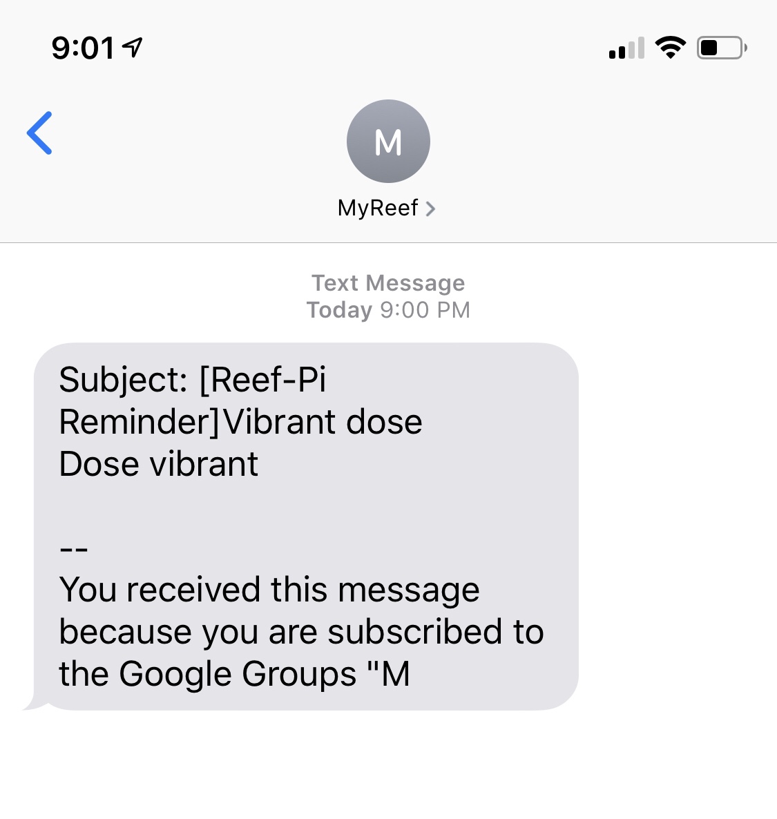
My first official txt (aside from testing) from reefpi.


86f1517681fae0c938d5252bea96dab7.jpg
 

Diamond1

Valuable Member
View Badges
Joined
Oct 17, 2013
Messages
1,368
Reaction score
1,911
Location
Cleveland Ohio
Rating - 0%
0   0   0
Thanks for the input @theatrus. Starting under load was one of my concerns as well. @doughboy has a really good thread on the other forum that I still need to read through but it looks like it’s confirmed to work with the DCT series pumps. There are other versions of the controllers available but I still need to do some more research. There is also a Texas Instruments controller that you can fine tune via eprom but that may be a little too advanced for me.
Very interesting stuff. Have you made any progress on choosing a board to use for pump control?
I'm curious to know if the same board will work with the smaller Jabeo pumps like the older wp or newer tw models. I believe they also run on 24v dc.
 
OP
OP
b4tn

b4tn

Valuable Member
View Badges
Joined
Jun 17, 2015
Messages
1,673
Reaction score
2,241
Location
Columbia MD
Rating - 0%
0   0   0
Very interesting stuff. Have you made any progress on choosing a board to use for pump control?
I'm curious to know if the same board will work with the smaller Jabeo pumps like the older wp or newer tw models. I believe they also run on 24v dc.

I just finished reading through the thread on the other forum and it looks like the standard ebay board works but does not provide full power to the pumps. Looks like its highest setting is equal to the the original pump controllers lowest setting. Something to do with the signal input to the pump not being ideal for the coils. I think thats where @erk 's find on the TI chip would come in handy for tuning the output. Going to read that next.

Ultimately it would be nice to just highjack the input signal on the OEM controller. The driver is already there just need to find out where the input is. I might see if I can open up one of the controllers tonight.
 

theatrus

Valuable Member
View Badges
Joined
Mar 26, 2016
Messages
1,957
Reaction score
3,355
Location
Sacramento, CA area
Rating - 0%
0   0   0
I just finished reading through the thread on the other forum and it looks like the standard ebay board works but does not provide full power to the pumps. Looks like its highest setting is equal to the the original pump controllers lowest setting. Something to do with the signal input to the pump not being ideal for the coils. I think thats where @erk 's find on the TI chip would come in handy for tuning the output. Going to read that next.

Ultimately it would be nice to just highjack the input signal on the OEM controller. The driver is already there just need to find out where the input is. I might see if I can open up one of the controllers tonight.

This is by far the easiest approach. Even if it’s push button speed control, you can just use GPIO to electrically push the buttons :)
 

erk

Valuable Member
View Badges
Joined
Mar 19, 2014
Messages
1,382
Reaction score
2,049
Location
DFW
Rating - 0%
0   0   0
I just finished reading through the thread on the other forum and it looks like the standard ebay board works but does not provide full power to the pumps. Looks like its highest setting is equal to the the original pump controllers lowest setting. Something to do with the signal input to the pump not being ideal for the coils. I think thats where @erk 's find on the TI chip would come in handy for tuning the output. Going to read that next.

Ultimately it would be nice to just highjack the input signal on the OEM controller. The driver is already there just need to find out where the input is. I might see if I can open up one of the controllers tonight.

I tried to find the input on the old gyre controller boards, but it is pretty difficult. I'm seriously considering the new gyre controllers because they have 0-10V control inputs. Not sure if the Jebao pumps have a controller with 0-10V inputs. Maybe you can replace the potentiometer with a digitally controlled one?
 

theatrus

Valuable Member
View Badges
Joined
Mar 26, 2016
Messages
1,957
Reaction score
3,355
Location
Sacramento, CA area
Rating - 0%
0   0   0
I tried to find the input on the old gyre controller boards, but it is pretty difficult. I'm seriously considering the new gyre controllers because they have 0-10V control inputs. Not sure if the Jebao pumps have a controller with 0-10V inputs. Maybe you can replace the potentiometer with a digitally controlled one?

A DAC or digital pot (assuming the voltage across the pot is <=5V) would be an easy to implement change. The DAC would give more resolution.
 
OP
OP
b4tn

b4tn

Valuable Member
View Badges
Joined
Jun 17, 2015
Messages
1,673
Reaction score
2,241
Location
Columbia MD
Rating - 0%
0   0   0
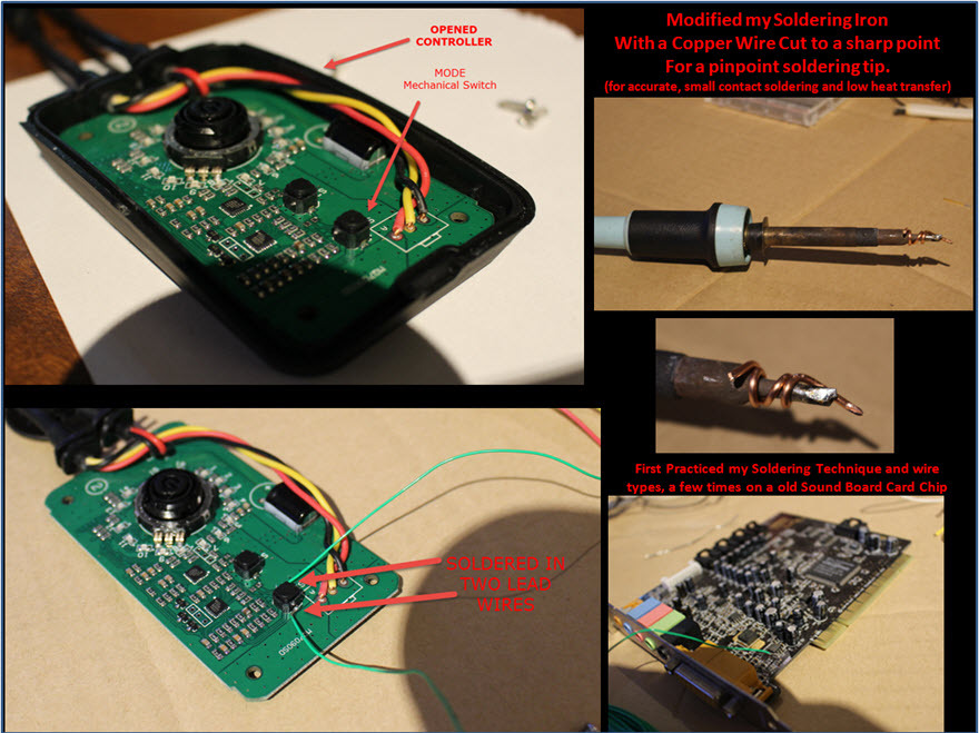
I found this image of the opened controller. It looks like its a 3 position pot. So in theory the center pin of the pot should be a variable 0-x volts. I would have to measure the range. But would it not work to find out what the variable voltage is, remove the center leg and input pi variable voltage there?

1-SolderInLeadWire_zpsl7zp4xvx.jpg~original
 

theatrus

Valuable Member
View Badges
Joined
Mar 26, 2016
Messages
1,957
Reaction score
3,355
Location
Sacramento, CA area
Rating - 0%
0   0   0
I found this image of the opened controller. It looks like its a 3 position pot. So in theory the center pin of the pot should be a variable 0-x volts. I would have to measure the range. But would it not work to find out what the variable voltage is, remove the center leg and input pi variable voltage there?

1-SolderInLeadWire_zpsl7zp4xvx.jpg~original

Effectively yes. There are two ways they could measure, current or voltage. Since this is a micro controller it’s most likely voltage, so any buffered DAC will work. Microchip makes a nice lineup of I2C DACs, some even have EEPROM on them so they start at your pre programmed set point (smart if you’re controlling a return pump for example, or fail safe for circulation).

A few LED drivers use a current sense, so a bit more circuitry is required to bias that correctly. But I don’t expect to see that here.
 
OP
OP
b4tn

b4tn

Valuable Member
View Badges
Joined
Jun 17, 2015
Messages
1,673
Reaction score
2,241
Location
Columbia MD
Rating - 0%
0   0   0
The DACs I was talking about in breakout board form:
https://www.adafruit.com/product/935

Depending on the voltage range, you may want to divide the output with a resistor divider.

Thanks, I was looking at that. Only issue I have 0 coding experience or knowledge. And this would require either build a driver for reef-pi version 3 or make separate code just for for it. Is there anything wrong with just making a low pass filter followed by an op amp? This way I can control the built in pwm with reefpi no coding needed on my part.
 

theatrus

Valuable Member
View Badges
Joined
Mar 26, 2016
Messages
1,957
Reaction score
3,355
Location
Sacramento, CA area
Rating - 0%
0   0   0
Thanks, I was looking at that. Only issue I have 0 coding experience or knowledge. And this would require either build a driver for reef-pi version 3 or make separate code just for for it. Is there anything wrong with just making a low pass filter followed by an op amp? This way I can control the built in pwm with reefpi no coding needed on my part.

Nope, that will work just fine as well.
 

crusso1993

7500 Club Member
View Badges
Joined
Oct 21, 2018
Messages
8,671
Reaction score
44,649
Location
SW, FL, USA
Rating - 0%
0   0   0

erk

Valuable Member
View Badges
Joined
Mar 19, 2014
Messages
1,382
Reaction score
2,049
Location
DFW
Rating - 0%
0   0   0
For anyone following along and so that I can come back to this later. An adjustable PWM to linear voltage converter. and the details on how it works.

https://www.allaboutcircuits.com/technical-articles/turn-your-pwm-into-a-dac/

https://www.raspberrypi.org/forums/viewtopic.php?t=124130

file.php

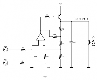
This is much better than what I did the first time I tried to convert PWM to 0-10V. For my first controller, an Arduino only, I used a transistor and connected the PWM to the gate. I had to do this because my LED driver only accepted 0-10V. Similar to what is shown below minus the comparator and just a single pulldown resistor. None of that extra stuff you see. Link to the site for the image below.

upload_2019-1-22_16-36-9.png
 
OP
OP
b4tn

b4tn

Valuable Member
View Badges
Joined
Jun 17, 2015
Messages
1,673
Reaction score
2,241
Location
Columbia MD
Rating - 0%
0   0   0
This is much better than what I did the first time I tried to convert PWM to 0-10V. For my first controller, an Arduino only, I used a transistor and connected the PWM to the gate. I had to do this because my LED driver only accepted 0-10V. Similar to what is shown below minus the comparator and just a single pulldown resistor. None of that extra stuff you see. Link to the site for the image below.

upload_2019-1-22_16-36-9.png

That link has a ton of useful information. Thanks for sharing.
 
OP
OP
b4tn

b4tn

Valuable Member
View Badges
Joined
Jun 17, 2015
Messages
1,673
Reaction score
2,241
Location
Columbia MD
Rating - 0%
0   0   0
@Ranjib I didnt want to clutter the main thread so I will put this here. I am getting frustrated with the macros and timers and wanted to check and make sure I am not doing anything wrong. I have two timers set up that activate a powerhead on each side of my tank. It is set up so that every hour they flip flop. left runs for an hour then turns off then right turns on for an hour and back and forth. Works great!
45946148395_a2dc2a8ff4_b.jpg


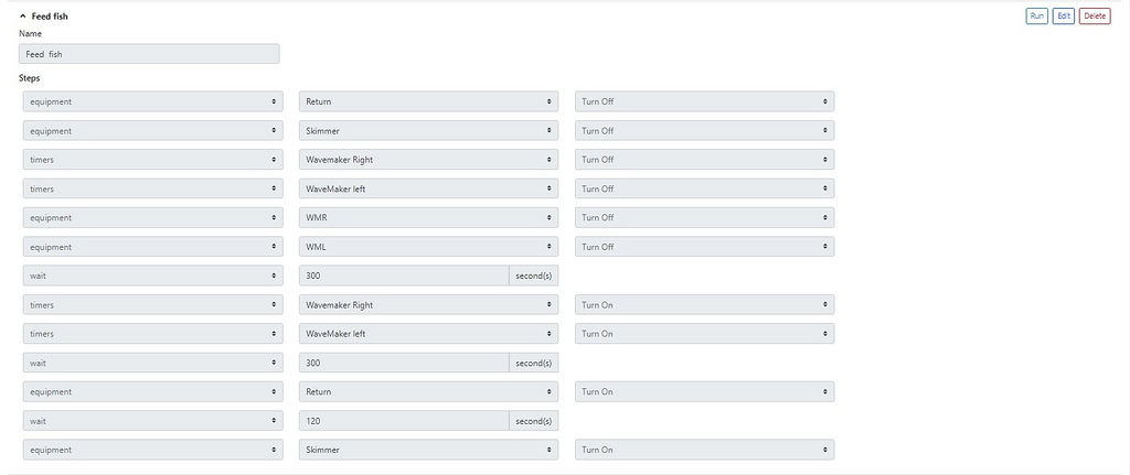
So on to the macro. I started building macros after I updated to 2.1. If I had any equipment on a timer if I turned it off it would come back on within 30 seconds picking up where the timer left off. So I wanted to turn off the equipment, disable the timers, then re enable the timers after a set time. In theory once the timer was active again the equipment would turn back on picking up where it left off. This was useful because at any given time one of the powerheads might be on or might be off so if I turned them both off and then both timers once the timers where back on they should pick up where they left off. My macro is set up like this.
39895918043_bce6eb05dc_b.jpg


This would work although randomly because the timers would not show up in the drop down unless I visited the timer tab first and then had to be quick to go back and run the macro. If I was fast enough and viewed the timer tab then clicked over to the macro tab and ran it, return, skimmer, and powerheads would turn off. After 5 minutes whatever powerhead was in its cycle would turn back on, 5 minutes later the return pump, then 2 minutes later the skimmer would come back on.

So I updated to 2.2 for the timer fix, rebooted, and ran the macro to test. The timers show up (awesome), ran the macro and everything stopped like it should (and stayed off), but now after the timers are supposed to come back on the power heads dont auto turn on where they left off. I went to the equipment tab and turned off a piece of equipment that was on a timer and it no longer auto turns back on after 30ish seconds. So before the update I could not get the timers/equipment to turn off and stay off now I cant get the timers/equipment to turn back on lol. Am I doing something wrong in the macro?
 
OP
OP
b4tn

b4tn

Valuable Member
View Badges
Joined
Jun 17, 2015
Messages
1,673
Reaction score
2,241
Location
Columbia MD
Rating - 0%
0   0   0
I am going to stop messing with it. I have been messing with it all day trying different things and cannot get a consistent result. I am back again to not being able to get timers to stay off but building some test macros earlier today I was able to get it to work just fine. I made a simple macro to turn off power head timers, turn off power heads, wait 120 seconds, turn on power head timers. This worked with no issue. Once the timers where turned off via the macro the pumps did not come back on. Timers came back on 120 seconds later and one of the pumps would come on as expected.

I tried again a couple hours later to run the same macro that was working before and power heads go off then come back on 30 sends later. The Macro still shows "running".

I disabled the power head timer manually, saved it, and then turned off the pump and 30 seconds later the pump turned back on and the timer was still listed as being disabled. It appears that timers are not staying turned off. What is driving me crazy is I cant figure out what it is I do that makes them sometimes work.
 
Last edited:

Ranjib

7500 Club Member
View Badges
Joined
Apr 16, 2016
Messages
9,843
Reaction score
17,058
Location
Pleasant Hill, Concord
Rating - 0%
0   0   0
I am trying to decipher the issue here. It looks like some interplay between timer and macro. If you can share a smaller example that I can use to reproduce, that will be awesome.
The "running" button in macro is not realtime, the macro label changes from "run" to "running" when you click on it, and then polls the api at 10 second interval (to avoid hammering the actual controller). It will only go to "run" again after the api has returned macro is done (at 10 second interval).
I'll add some logging statement in the code to make it more obvious when timer is being kicked on/off , macro is being kicked on/off etc. I think they are already there, so if you can stream logs
Code:
journalctl -fu reef-pi.service
and click on macro/timers etc.. you should see what reef-pi is doing.
I agree we need to do a lot better job in showing the state of affairs in the UI
 

Reefing threads: Do you wear gear from reef brands?

  • I wear reef gear everywhere.

    Votes: 13 21.7%
  • I wear reef gear primarily at fish events and my LFS.

    Votes: 2 3.3%
  • I wear reef gear primarily for water changes and tank maintenance.

    Votes: 0 0.0%
  • I wear reef gear primarily to relax where I live.

    Votes: 7 11.7%
  • I don’t wear gear from reef brands.

    Votes: 33 55.0%
  • Other.

    Votes: 5 8.3%
Back
Top