Apex DOS DIY level switch?

Script_Kitty

Community Member
View Badges
Joined
Nov 10, 2017
Messages
95
Reaction score
143
Rating - 0%
0   0   0
Does anyone, or has anyone tried, how to wire up an optical sensor to a 3.5mm jack? I know if has to be a 4 conductor but just don't know what goes to each segment. Where to get jacks?
Thx

I am in the process of trying to work this out for my system. I have the neptune optical sensors and thanks to CuseReefers, i am i the process of trying to connect them to up.

Assuming they are the same as the diagram CuseReefer posted, i should be able to figure out the pins with a multi meter.

Give me a bit and i will post the results.


And CuseReefer, thanks for figuring out the basics, i searched everywhere for what you figured out. Was about to break open a dos to look at the boards.
 

Script_Kitty

Community Member
View Badges
Joined
Nov 10, 2017
Messages
95
Reaction score
143
Rating - 0%
0   0   0
Ok, that was a lot harder than i thought.

Turns out the jacks i gor from digi-key wouldnt quite fit in the holes of the FMM and failed to connect like they should.

I compared it using the optical sensors from ebay with the neptune optical sensors i have from neptune.

Assumig the color code for the ebay sensors as listed in this thread. The wiring to the FMM jack is:

(Base, closest to insulation)
Pin1 - Red
Pin 2 - Blue
Pin 3 - Yellow
Pin 4 - White


I had gotten part CP-35401SP-ND. Conn plug stereo 3.5mm 4cond. From digi-key, but its not the right one to connect to the FMM, it is a little to wide to fit through the FMM cover plate all the way.
SO DONT USE IT


Hopeing someone has found a good part for the plug.
 

Script_Kitty

Community Member
View Badges
Joined
Nov 10, 2017
Messages
95
Reaction score
143
Rating - 0%
0   0   0
I just hooked up ebay flow meters to my fmm. The optical sensors should work the same.
You have to wire the 4 optical sensor to an aux cable. For the flowmeter I wired it like this to the aux cable
(Base, closest to insulation) Pin1 - Ground
Pin 2 - Power
Pin 3 - Unused for flowmeter
(Tip) Pin 4- Signal

Id imagine if you wire the optical sensor in the same way but using the 3rd pin that it will work. I was gonna try this out tonight or tomorrow


Humpty, do you remember the part number of the jack you used for connecting to the FMM?

I used CP-35401SP-ND from digi-key,but it wasnt able to seat all the way in without removing the FMM cover plate.
 

scott711

Community Member
View Badges
Joined
Oct 25, 2007
Messages
57
Reaction score
8
Rating - 0%
0   0   0
I found this thread and was talking with rioreef. I ordered an optical sensor and I found a aux jack that fits in the FMM. The apex recognized the sensor. I just can't figure out the correct wiring. If I wire it according to humpty, it recognizes it as a flow meter, if I wire it how humpty said for a sensor, it will only recognize it in the closed state. The only way I get it to recognize it in an open state is by removing the sensor from the FMM completely.

Any ideas???
 

Script_Kitty

Community Member
View Badges
Joined
Nov 10, 2017
Messages
95
Reaction score
143
Rating - 0%
0   0   0
I found this thread and was talking with rioreef. I ordered an optical sensor and I found a aux jack that fits in the FMM. The apex recognized the sensor. I just can't figure out the correct wiring. If I wire it according to humpty, it recognizes it as a flow meter, if I wire it how humpty said for a sensor, it will only recognize it in the closed state. The only way I get it to recognize it in an open state is by removing the sensor from the FMM completely.

Any ideas???
How sure are you that your connectors are seating properly in the FMM module.

I ran into a lot of problems using ones that disnt seat all the way. The pins where not lining up right and connecting to different ports.

I ended up opening the box and putting a volt meter to a sample plug.

Did you try the wiring i posted 3 posts up?

And finally, how sure are you that the color on your sensors match the standard colors? (It probebly does, but worth checking).
 

scott711

Community Member
View Badges
Joined
Oct 25, 2007
Messages
57
Reaction score
8
Rating - 0%
0   0   0
Script_Kitty. Thanks for the reply. I actually worked on it more and got it to work! I redid all the wiring since the wires on optical sensor are so fine. I also made sure it was seated all the way in. I got the optical sensor to register "open" and "closed" by getting it wet. I will post the schematics/parts/etc. I am very excited that I got it to work.
 

scott711

Community Member
View Badges
Joined
Oct 25, 2007
Messages
57
Reaction score
8
Rating - 0%
0   0   0
Here are screenshots of the sensor changing states.
3f64226a509abd47fa8fa2d12b11ec0a.jpg
5401a9812fa328e7c846ec2006249cb4.jpg
 

Script_Kitty

Community Member
View Badges
Joined
Nov 10, 2017
Messages
95
Reaction score
143
Rating - 0%
0   0   0
Great. Do you have the part number for the jack your using? The ones i got dont sit in the ports deap enough?
 

Script_Kitty

Community Member
View Badges
Joined
Nov 10, 2017
Messages
95
Reaction score
143
Rating - 0%
0   0   0
I went back and checked the wiring that worked for me. I wanted to make sure that i didnt mess something up when translating the cable colors from my test rig.

I am able to get the optical sensors to open and close (apex.local is faster for testing than fusion by the way) using the following:

Pin one (closest to base of plug) Red
Pin two Blue
Pin three Yellow
Pin four White

I have included the below from my notebook to clear up any confusion on which pin was 1.

image.jpg


The part that worries me the most, is fear that different optical sensors might have different color wires.

I tried to figure out a way to test them but havnt figured out a good way yet.

If i contect up a multi-meter in diod mode with positive to blue, and common to red, I read 1.033 ohms. (Referse i read as open). I used this and reefers doc to figure out the blue and the red. But for the yellow and white, i couldn’t come up woth a good test, and ended up having to go with trial and error.


The while process was confusing because my plugs wouldnt sit all the way down, amd would connect to different ports. Ended up taking the face plate off and testing connectivity to the board.
 

scott711

Community Member
View Badges
Joined
Oct 25, 2007
Messages
57
Reaction score
8
Rating - 0%
0   0   0
I went back and checked the wiring that worked for me. I wanted to make sure that i didnt mess something up when translating the cable colors from my test rig.

I am able to get the optical sensors to open and close (apex.local is faster for testing than fusion by the way) using the following:

Pin one (closest to base of plug) Red
Pin two Blue
Pin three Yellow
Pin four White

I have included the below from my notebook to clear up any confusion on which pin was 1.

image.jpg


The part that worries me the most, is fear that different optical sensors might have different color wires.

I tried to figure out a way to test them but havnt figured out a good way yet.

If i contect up a multi-meter in diod mode with positive to blue, and common to red, I read 1.033 ohms. (Referse i read as open). I used this and reefers doc to figure out the blue and the red. But for the yellow and white, i couldn’t come up woth a good test, and ended up having to go with trial and error.


The while process was confusing because my plugs wouldnt sit all the way down, amd would connect to different ports. Ended up taking the face plate off and testing connectivity to the board.
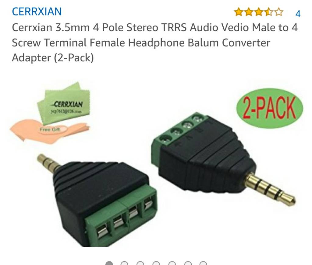
Good info. I have to look and see what the layout was for mine. This is the aux 3.5mm connector I used. I trimmed a little of the rubber part at the end to make sure I had a good connection. I liked this connector since I could insert and secure the wires very easily.

Script_kitty what connector did you end up using?
61fa8029b8a6b467f2bcf55d66797d4b.jpg
 

Script_Kitty

Community Member
View Badges
Joined
Nov 10, 2017
Messages
95
Reaction score
143
Rating - 0%
0   0   0
The funny part is that i am not actually trying to connect up the optical switches to the FMM, i have a set of four neptune ones that i have in some custom DDR containers i built (have space limitations) and need to make a converter cable to let me plug them into the dos.

Finally got it working tonight pin wise, and will finish out the cable tommarow.

I kept running into connectivity issues in my testing. Turns out one of my test rigs developed a fault after checking it 5 times during construction. Was frustrating because the math said it should work, and the pre tests siad it should work...

In the end, i got it working and the two optical sensors show up just like FMM optical sensors.

No if i can hust figure out whats wrong with my 1 1inch flow sensor. I finally got my sump in after waiting 2 months, and got all the plumbing in. But the overflow flow sensor started ******* up to 9k gallons per hour (on a 32 gallon biocube). At first i though it was cross talk from the cor 15, but now i am not so sure.
 

dovla

New Member
View Badges
Joined
Jul 13, 2017
Messages
11
Reaction score
0
Rating - 0%
0   0   0
Script_Kitty, Neptun sensors have white, red, black and green wires. To which DOS pin each one does it go? Thanks
 

Script_Kitty

Community Member
View Badges
Joined
Nov 10, 2017
Messages
95
Reaction score
143
Rating - 0%
0   0   0
I havnt cut open the neptune optical sensors yet to see which one goes where, i have been making a cable that i can plug my existing neptune optical cables into without having to cut off the ends.

If you have one cute open, amd can tell me which wire goes to which pen, i can tell you which wire lines up with the ddr pinout that Reefer worked out at the start of this thread.
 

dovla

New Member
View Badges
Joined
Jul 13, 2017
Messages
11
Reaction score
0
Rating - 0%
0   0   0
Neptune optical sensor connector wires are:

Pin one (closest to base of plug) Red
Pin two Green
Pin three Black
Pin four White
 

dovla

New Member
View Badges
Joined
Jul 13, 2017
Messages
11
Reaction score
0
Rating - 0%
0   0   0
Script_Kitty, it works!

Thank you for your drawing and pin to wire color list above.
 

Script_Kitty

Community Member
View Badges
Joined
Nov 10, 2017
Messages
95
Reaction score
143
Rating - 0%
0   0   0
Great, so it looks like the Green is the Blue wire, and the Black is the Yellow.
 

Engloid

Valuable Member
View Badges
Joined
Mar 26, 2010
Messages
2,082
Reaction score
315
Location
Tennessee
Rating - 0%
0   0   0
I'm not great with electronics, and am looking for a way I can hook an amazon bought optical sensor to the breakout box. Is the info here in the thread, in one place, or scattered? If it's scattered, I'm missing it. I have been told I will need a 5v power supply. I'd like to power a few or them, so what amp rating would I need on the power supply?
 

Greenstreet.1

5000 Club Member
View Badges
Joined
Oct 16, 2013
Messages
5,719
Reaction score
3,242
Location
Li New York
Rating - 0%
0   0   0
All. I am currently working on a breakout pcb board that will connect to the din8 connector on the apex (io port) that will let you connect multiple optical sensors as well as normal contact switches (magnet/float/etc). This will take a few weeks but should have prototypes within the month. The board will have connectors so you can directly connect the optical sensors and 1/8" headphone jacks for standard sensors. Also will have a power input port for a 5v wall supply to power the optical sensors.

I sent you a pm on Neptune form about this is it still available ? Would like to get one.
 

Creating a strong bulwark: Did you consider floor support for your reef tank?

  • I put a major focus on floor support.

    Votes: 56 40.3%
  • I put minimal focus on floor support.

    Votes: 29 20.9%
  • I put no focus on floor support.

    Votes: 49 35.3%
  • Other.

    Votes: 5 3.6%
Back
Top