



Dirt Diggler's Reef-pi Build

Still nothing. I did get a voltage increase on the signal wire, it jumped to .1 volts. Any ideas as to what could be wrong?
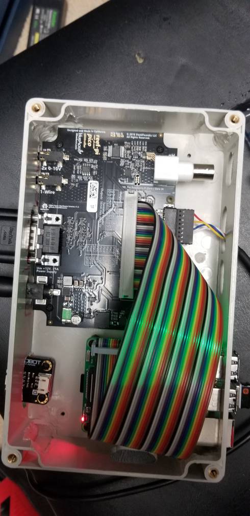
20190110_184745.jpeg
 
Still nothing. I did get a voltage increase on the signal wire, it jumped to .1 volts. Any ideas as to what could be wrong?
20190110_184745.jpeg

Looks like it’s still wired on the output side as well.

In order to bypass the converter board you need two resistors: one to limit current and one as a pull-up.
 
Looks like it’s still wired on the output side as well.

In order to bypass the converter board you need two resistors: one to limit current and one as a pull-up.
The GND only appears on the output side. Could you share a drawing of how I should wire this in?
 
It does not come with that small board that the DFRobot sensor comes with. Are you using a pico board?
No I'm using a wykat board that has the circuit built into the board. You still need to use the board for that sensor. Not familiar with the pico boards cicuit layout but the dfrobot board you have should work for that sensor and then connect to the pico board.
The circuit for wykats hat uses a 100nf capacitor, a 4.7k and 360k resistor. If the circuit for the pico board was made to use a mechanical float switch than the DFRobot board needs to be in there too. You just need to double check that the wiring from the board matches the pico board connectors. I will defer to @theatrus for confirmation of this since I'm not familiar with his boards layout.
 
No I'm using a wykat board that has the circuit built into the board. You still need to use the board for that sensor. Not familiar with the pico boards cicuit layout but but the dfrobot board you have should work for that sensor and then connect to the pico board.
The circuit for wykats hat uses a 100nf capacitor, a 4.7k and 360k resistor. If the circuit for the pico board was made to use a mechanical float switch than the DFRobot board needs to be in there too. You just need to double check that the wiring from the board matches the pico board connectors. I will defer to @theatrus for confirmation of this since I'm not familiar with his boards layout.

I could have just had a bad sensor, which is what I'm hoping happened. I'll give this a go, but if I can't get it to work, then I'll get some float switches. Right now I'm manually turning on the ATO system daily to keep things at the proper level.
 
You'll need that small breakout board for these optical (photo electric) sensors. These are required for pico base board (theatrus) as well. The pico based board can use float sensors directly.
 
You'll need that small breakout board for these optical (photo electric) sensors. These are required for pico base board (theatrus) as well. The pico based board can use float sensors directly.

Awesome. I still have that board installed. I'll probably get some float switches just in case this optical sensor is a dud as well.
 
Are they sealing it first?

You know, I really do not know if they are being sealed. However, regardless of what others are doing, I would put a coat of silicone on them just for peace of mind.
 
You know, I really do not know if they are being sealed. However, regardless of what others are doing, I would put a coat of silicone on them just for peace of mind.

Silicone does not have a good track record thus far. Maybe some plasti-dip.
 
Silicone does not have a good track record thus far. Maybe some plasti-dip.

Thanks for the heads-up! I was not aware there were problems. I know I wouldn't use 2 part epoxy either because of the degradation with time in SW.
 
You know, I really do not know if they are being sealed. However, regardless of what others are doing, I would put a coat of silicone on them just for peace of mind.
I am not sealing mine for waterproof of the sensor, I have 2 of these and 2 more on the way, they are double crimped onto heavy silicone insulated wire...ones I have do not stick to a magnet...which is good enough stainless for a FW tank. YMMV in salt.

20190103_004315.jpg
 
Got my new sparkfun temp probe, and 3.5mm jacks. I've tipped the probe, and incorporated it with no issues. It looks much better built than the first one, as it is completely sealed. I've already tied it into the heaters for a nice 78.5 degree temp. We will see how it does against the standalone thermometer I have already on the DT. I've also ordered two of the probes that @Bigtrout recommended. I've also added a cheap belkan speaker/headphone splitter, which seems to work fine right now with one probe hanging off of it. Once I add a second, I'll understand more. This may help make the probes themselves more modular and easy to replace.
 
@DirtDiggler2823 lets get to the bottom of adafruit.io issue here. Can you share the following
- Screen shot of one of your ATO or temp tab. Make sure theres no space in the name of sensors (temp or ato)
- Screenshot of your telemetry config (blur out the aio key, we dont need it)
- Open a terminal and run journalctl -fu reef-pi.service, we want to see the log as we issue a reload command from reef-pi
- Issue a resload command from reef-pi ui (Configuration admin)
- Share a screenshot of your log as the reload command takes in effect
 

TOP 10 Trending Threads

ARE YOU READY TO CONFESS TO CRAZIEST, DUMBEST, FUNNIEST THING YOU’VE EVER DONE IN REEFING?

  • Yeah, I'll confess! (Share your story in the comments!)

    Votes: 33 57.9%
  • Nah, I'll keep mine a secret...(Don't be like that, share with the class!)

    Votes: 24 42.1%
Back
Top
Home
Post thread…
Market
What's new






