DIY ATO on the Cheap

redfishbluefish

Stay Positive, Stay Productive
View Badges
Joined
Mar 22, 2012
Messages
11,705
Reaction score
25,724
Location
Sayreville, NJ
Rating - 0%
0   0   0
My wife always complains that I'm cheap, and still have my Communion money. Here is my shot at a DIY for a float switch with minimal expendature. Note that this could be used for an ATO by simply adding a small pump, such as a Tom's Aqualifer. I will give as much detail as I can, including were I purchased and how much I paid. This is a work in progress, so I'm hoping it works when I get done. The disclaimed is that I know as much about brain surgery as I do about electronics....you've been warned. :D

To start this project off I ordered/purchased the following items:

Double Pole Relay from Amazon............................................$3.25 (free shipping)
Float Switches from eBay..........................................................$1.00 (free shipping)
Electrical Box for Home Depot................................................$1.28 (tax included)

I actually purchased five of the float switches, but for this project, I'm only using one (for now). If you're building an ATO, I'd highly recommend using two float switches connected in series, with one float switch slightly higher than the other. This "higher" switch is the secondary fail switch when the first one fails.....and it will fail!

The first thing I did was make a project box for the relay. I used an inexpensive plastic electrical box from HD.


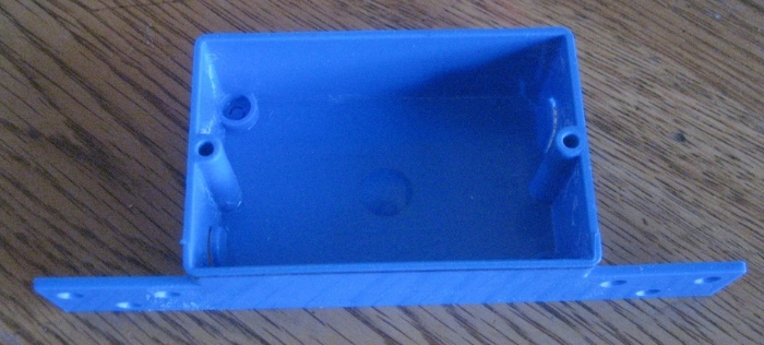
I cut off the tails, and using a scrap pieces of acrylic, made a cover for the box. Now the relay doesn't fit into this box, but the only thing I need to protect are the electrical contact screws from my fat fingers....especially the 110 volt side. :eek:


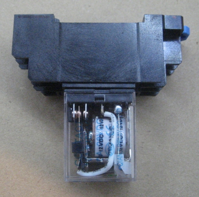
So to make it fit in the box, I cut a hole in the side to fit the relay itself. This reminded me of the audio freaks I know who have tubed amplifiers where the tubes are exposed. They are under the belief that their crappy human ears can distinguish the oh-so-slightly improved sound quality.

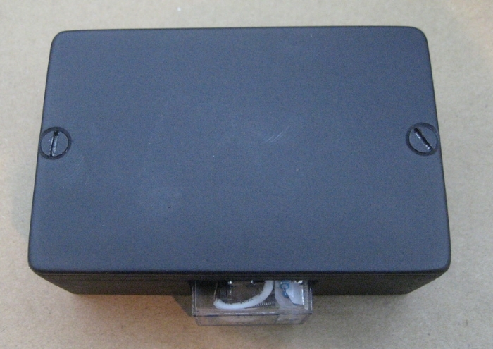
With a shot of my favorite black spray paint (98 cents a can), here's the project box with relay.


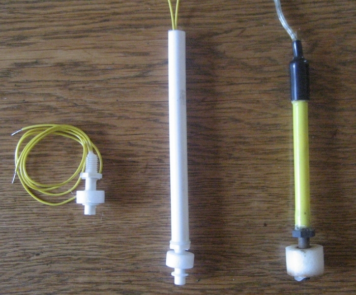
For the float switch, the old one was on a rod portion, and attached with a screw clamp. To replicate this rod portion, I took the fattest plastic hanger I could find and cut it up. To my surprise, part of the inside already had a hole. Using a long bit (masonry hammer bit), I finished drilling the center of the rod. I then drilled and tapped the one end of the rod to fit the float switch. The threading was M8-1.25 (metric). I don't have metric drills, but the 17/64 inch (0.26563"), bit was close enough to the required 0.26378 inch hole that was needed. From left to right, the new float switch, the new float switch attached to a piece of hanger rod, the old float switch.


I'm at a stand still right now because the numbering on the relay plug is different from what I'm use to......and the battery in my multimeter is dead to figure out the arrangement. TO BE CONTINUED!

Expenditure so far.......$5.53. If you want to include the paint (I had that sitting around, and it only took a squirt), add another $0.98.
 
OP
OP
redfishbluefish

redfishbluefish

Stay Positive, Stay Productive
View Badges
Joined
Mar 22, 2012
Messages
11,705
Reaction score
25,724
Location
Sayreville, NJ
Rating - 0%
0   0   0
Well, that didn't last long! I decided to splurge and spend a whole buck on a second back-up float switch.

Using scrap acrylic, made a little bracket to hold a second float. Angle drilled into the rod to run the wires.


I'll be using this particular setup on the skimmate container to assure it won't overflow....if and when my skimmer goes nuts. The time I've had the skimmate container, the float switch has only been used once. But for an additional dollar, why not have the backup.
 
OP
OP
redfishbluefish

redfishbluefish

Stay Positive, Stay Productive
View Badges
Joined
Mar 22, 2012
Messages
11,705
Reaction score
25,724
Location
Sayreville, NJ
Rating - 0%
0   0   0
I've come to the realization that I'm the oddball with all the tools I have, and the extra time I have to tinker and play. Accordingly, I've given some thought to the skill and tool requirements for this little DIY. So far I've used my drill press, cut off saw, power rasp, small hand saw, file, drill bits, taper bit, and metric tap and die kit. I realize I'm the oddball with the tools, so as an alternative, the AquaHub Premium kit is a good second choice.....for about $40. It's still semi-DIY, but requiring minimal hand tools. HERE's the link to that kit.....also note the disclaimer on their site, especially if you're not comfortable with electricity. With this kit, if you're interested in an ATO, you will still need an outlet box, cover and plug along with a pump and tubing....Tom's Aqualifter for ca $15 works well. Hope this helps with those who are not as crazy with the tools.
 

Rybren

Valuable Member
View Badges
Joined
Jun 13, 2011
Messages
1,494
Reaction score
1,908
Location
Ottawa, ON
Rating - 0%
0   0   0
The kind folks at aquahub have some good diagrams to help you with the relay wiring.

I built one similar to yours and used their site to figure out the wiring. I sold the tank that it was on, but the fellow who bought it from me is still using it.

Oops. Got distracted when typing and hit send without seeing your latest post and link to Aquahub. :oops:
 
OP
OP
redfishbluefish

redfishbluefish

Stay Positive, Stay Productive
View Badges
Joined
Mar 22, 2012
Messages
11,705
Reaction score
25,724
Location
Sayreville, NJ
Rating - 0%
0   0   0
Thanks @Rybren for the response and the heads-up. I'm aware of the contacts on the bottom of the relay...coil, common, normally open, and normally closed. Where I'm having the problem is the numbering on the relay plug, and what numbered screw goes to what numbered contact on the relay. With a multimeter, it's known within seconds.....but mine has a dead battery. So until I get a battery, I don't want to chance what I think it is to what it really is. Does that make sense.

To put it another way, I looked at the Aquahub instructions, and their relay plug from left to right appears to be numbered 3/4, 1/2, 7/8, 5/6. The relay plug I have is number left to right 1/2, 3/4, 5/6, 7/8. The "coil" screws on the AquaHub are 7/8. On mine, are the coil screws 5/6 (same location as AquaHub), or the 7/8 screws? That's why I want to double check with a multimeter.

But again, thanks for the heads-up.
 
Last edited:
OP
OP
redfishbluefish

redfishbluefish

Stay Positive, Stay Productive
View Badges
Joined
Mar 22, 2012
Messages
11,705
Reaction score
25,724
Location
Sayreville, NJ
Rating - 0%
0   0   0
As I had mentioned, this float switch is for a DIY Skimmate Container I made about three years ago. To add a little back-story, the original float switch didn't have a relay associated with it. It had some crazy electronics that were way above me (That's easy to do.) Maybe some of the electrical folks could figure this out, but here's what I had:


The speaker wire went to the float switch, and that outlet was for the skimmer. If the float switch was activated, the skimmer pump stopped. Here's a close up of that mess:


What has caused for me to change this float switch arrangement is that the Atman pump on my skimmer died, and in the process blew the 15 amp fuse in the ReefKeeper. In the process it must have also cooked something in the float switch department, because it no longer worked. Instead of trying to figure out these unknown electronics (to me), I decided to go for a whole new float switch assemble....something that I understood (with a relay).


Now back to present day, I wanted to make sure the new float switch assembly would fit without interfering with the sides of the skimmate container and drain tube.


Like a glove!

I must say, sometimes the serendipity of my designs even impress me! Hold on one moment while I reach around and pat myself on the back. I'm very happy with how this turned out and glad I included the second float switch. Someone recently posted about "Chinese" float switches, and I feel a little better knowing I have the back-up.

Now I need a battery to get my multimeter going to continue this journey.
 

revhtree

Owner Administrator
View Badges
Joined
May 8, 2006
Messages
47,786
Reaction score
87,400
Rating - 100%
1   0   0
Following!
 
OP
OP
redfishbluefish

redfishbluefish

Stay Positive, Stay Productive
View Badges
Joined
Mar 22, 2012
Messages
11,705
Reaction score
25,724
Location
Sayreville, NJ
Rating - 0%
0   0   0
Thanks Rev!

With the multimeter now working, I believe it is the numbers on the relay plug that are important, not the physical locations of the screws/connectors. So connection 7 and 8 are the coil (regardless of where they are located), even though on this plug they are the most "right" connectors. With this now known, here's my wiring diagram. Note I am using a regular wall outlet, that is mounted in my equipment cabinet, to use to plug in what I wish to control. In my case it's a skimmer. If you were making an ATO, you'd plug the reservoir pump into this outlet. Hope this diagram is understandable.


The small little trapezoid shapes are wire nuts.
 
Last edited:

Rybren

Valuable Member
View Badges
Joined
Jun 13, 2011
Messages
1,494
Reaction score
1,908
Location
Ottawa, ON
Rating - 0%
0   0   0
Glad you got it figured out.

Nice handiwork, btw. I just used an old tupperware container and it wasn't pretty.
 

AZDesertRat

5000 Club Member
View Badges
Joined
Feb 25, 2009
Messages
5,090
Reaction score
1,324
Location
Phoenix AZ
Rating - 0%
0   0   0
The most important thing I don't see mentioned is a DC power supply. You never want to run 120v AC power through micro float switches, the arc when switching on and off burns them up very quickly and can be dangerous around water. I have worked in the water industry for over 40 years and we always use low voltage DC power for control circuits such as this.
The use of the ice cube type relay allows you to switch an AC powered pump on and off using a DC powered switch via the floats.
I have also found the horizontal style snap action switches hold up much better than the vertical style and don't require as frequent cleaning. It's easy to make a bracket that hangs on the side of something out of acrylic and drill a couple of holes in it however many inches apart vertically you desire. My ATO has switches set 12" apart so it doesn't cycle on and off frequently.
 
OP
OP
redfishbluefish

redfishbluefish

Stay Positive, Stay Productive
View Badges
Joined
Mar 22, 2012
Messages
11,705
Reaction score
25,724
Location
Sayreville, NJ
Rating - 0%
0   0   0
@AZDesertRat I haven't gotten to talking about the 12V power supply yet, but it is shown in the above wiring diagram. Using a relay, I assumed the power supply was implied.....why else would you use a relay??? Since it's a 12 v relay, I will be using a wall transformer that puts out 12 VDC at 0.5 A.....more than enough.

That's interesting what you say about horizontal switches.....I'll be using one for my ATO reservoir to simply light an LED to let me know it needs water.....I'll document that when I get to it. But for my current ATO (since 2008) I have never cleaned the vertical float switches...and didn't have to. It is a dual switch setup and I did have to replace the primary float switch a couple years ago....but that's expected and why I run with the secondary float switch.

I'm also confused about your ATO having switches 12 inches apart. Are you saying the water level has to drop 12 inches before the pump comes on...to then fill that water back up those 12 inches? If so, that seems a bit drastic. I'm not sure if it's termed hysteresis with a float switch and even if it's built into it or not, but it does appear to happen......a slight overfilling, or a lag in coming back on. I haven't sat there to watch my float switches, but I also have never noted them coming on with frequency. If I were to guess, I'd guess every hour or two, they turn on. I will tell you that the Tom's Aqualifter I use lasted about 9 years before I put a rebuild into it.....just recently.
 

AZDesertRat

5000 Club Member
View Badges
Joined
Feb 25, 2009
Messages
5,090
Reaction score
1,324
Location
Phoenix AZ
Rating - 0%
0   0   0
It is my ATO storage that has float switches 12" or 11 measured gallons apart in a 23 gallon Rubbermaid can. This is so the RO/DI system does not cycle on and off leading to TDS creep issues and short membrane and DI life.
My sump has a digital air switch which is adjustable between 1/10" and 4" and I have it set at about an inch so it tops off from the ATO storage a couple times a day.

Both systems are 24v DC so intrinsically safe and have been on use for over 8 years trouble free.
 
OP
OP
redfishbluefish

redfishbluefish

Stay Positive, Stay Productive
View Badges
Joined
Mar 22, 2012
Messages
11,705
Reaction score
25,724
Location
Sayreville, NJ
Rating - 0%
0   0   0
Thanks @Rybren and @s2nhle .


Hit another brick wall today....I have a shoe box of power supplies (wall warts), and would have sworn I had a 12 v in the box.....to run the relay coil. No luck! So I just ordered one and hopefully it will be here in 3 to 4 days. Another $2.95 spent, for those keeping count.

However, I still got a couple things done. Using shrink tubing, I soldered the float switches in series and covered with the tubing. My diagram shows a wire nut, but instead I soldered it up and covered with the shrink tubing.....looks cleaner.


I also drilled the holes for the wiring going into the project box, and mounted that inside the equipment stand. The slot you see below and to the left is where the skimmate container sits. For those following my tank build HERE, this is in the Belly of the Beast.


I also wired up the relay for the 120 V side, and tinned all stripped wire ends. In addition, I cut out the old burnt up electronics from the outlet box, from the old float switch. When the power supply arrives, I'm all set to simply put it in and close up the box.
 
Last edited:

ngvu1

Valuable Member
View Badges
Joined
Mar 5, 2014
Messages
2,254
Reaction score
1,047
Location
Orange County, CA, USA
Rating - 0%
0   0   0
I am following along. I did build my ATO system a while ago and it worked for more than 3 years...I use solid state relay. The solid state relay uses 3-12V DC adapter so I used 1 of those old cell phone charger for that........
I did not like my DIY hanging clips for the float switches cause I just bent some acrylic pieces....so they are kind of ugly. I don't have the box for the relay either so wires are kind of hanging every where :)

Now I use the break out box and Apex for ATO........and I bought the hanging clips cause my handy skill has not improved! :)
 
OP
OP
redfishbluefish

redfishbluefish

Stay Positive, Stay Productive
View Badges
Joined
Mar 22, 2012
Messages
11,705
Reaction score
25,724
Location
Sayreville, NJ
Rating - 0%
0   0   0
I just so happen to look up the specific spec sheet on the relay I'm using.......HERE.

To repeat my first post, I don't know electronics, and was told that polarity doesn't matter with the relay....positive and negative leads could be switched, and everything would still work. Well the data sheet shows post/screw #8 as being positive. So when the power supply gets here, that's how it's going to be hooked up. Now who was that person who told me it doesn't matter which way they get hooked up? I do wish I knew what I was doing.

Otherwise, everything is all done, waiting for the power supply to arrive. The float switch is mounted in the skimmate container and one wire attached to the relay (post #7); Outlet all wired and closed up; relay wired for 120V......all done. Here's the skimmate container:


Here's the tally of expenditures so far

Double Pole Relay from Amazon..........................................$3.25 (free shipping)
Float Switches from eBay (x2)..............................................$2.00 (free shipping)
Electrical Box for Home Depot.............................................$1.28 (tax included)
Power Supply from eBay.......................................................$2.95 (includes shipping)
Miscellanous**......................................................................$3.00
TOTAL...................................................................$12.47
**Miscellanous - this is a guess of the value of the stuff I already had....shrink tubing, screws, acrylic, etc.
 
OP
OP
redfishbluefish

redfishbluefish

Stay Positive, Stay Productive
View Badges
Joined
Mar 22, 2012
Messages
11,705
Reaction score
25,724
Location
Sayreville, NJ
Rating - 0%
0   0   0
Finishing it Up

The wall transformer arrived today, and this was the last piece needed to finish up this little DIY. The positive side of the 12v transformer was attached to terminal #8 on the relay, and the negative was wire nutted to the remaining float switch wire.

Unexpectedly, this relay has an LED in it that is lit when the float switches are "open." With me cutting the project box to expose the relay, I might have put this some place were it would be visible. After wiring everything up, the project box was mounted. Here you can see the relationship to the project box (lower right), to the outlet plugs for the skimmer (and biopellet reactor)....the white outlet plug setup.


When the shelf is installed in the equipment cabinet, the project box/relay will not be seen.


FINAL ANALYSIS

So I wanted to see how cheap I really was with this build....since it's titled "on the cheap." Since AquaHub sells the parts to build your own, I used them to compare the price of my build. Note that I have not included shipping for the AquaHub prices. (Also note that I could buy their AquaHub Premium kit for less than the price of these individual parts...that are included in that kit.... for $39.95)

..........ITEM.................................................DIY.................AquaHub
Double Pole Relay/Socket.......................$3.25 .................$12.98
2 Float Switches.......................................$2.00.................$13.98
Project Box ..............................................$1.28...................$7.39
12V Wall Transformer..............................$2.98..................$7.59
Miscellaneous.............................................$3.00...................------
TOTAL..........................................$12.47.............$41.94


Not bad....roughly $13 versus $42....so for approximately a third of the cost you could have a float switch.

Now I didn't include labor. If I were to use the last job I had....consultant for the pharmaceutical/medical device industry......at my charge out rate.....labor would come to about $2000. So for a mear $2012.47 this float switch could be yours! :eek: What a bargain. :D


EDIT TO ADD: It just hit me! DOH! The reason they wanted you to hook positive to terminal #8 is because of the LED that's in the relay.....LED's need to be hooked up with the correct polarity. That's why it was important with this relay.
 
Last edited:

s2nhle

Valuable Member
View Badges
Joined
Mar 12, 2013
Messages
1,413
Reaction score
317
Location
VA
Rating - 0%
0   0   0
nice. what is the part number for the double pole relay/socket?
 

Creating a strong bulwark: Did you consider floor support for your reef tank?

  • I put a major focus on floor support.

    Votes: 45 41.3%
  • I put minimal focus on floor support.

    Votes: 23 21.1%
  • I put no focus on floor support.

    Votes: 38 34.9%
  • Other.

    Votes: 3 2.8%
Back
Top