OP
OP
redfishbluefish
Stay Positive, Stay Productive
View Badges
Super Moderator
Ultimate Member
Reef Squad
Excellence Award
Article Contributor
NJRC Member
Hospitality Award
My Tank Thread
Equipment Cabinet Installed
Wow Kevin, you weren't kidding! What a long day. I started at 7AM and didn't stop until around 10PM. The installation isn't finished, but I am! I just wished I had a Scotch to sip on while I type this.
Began the day by moving furniture and getting everything staged. Thought about those things I could disconnect and leave disconnected with minimal impact on the tank. So the first things I did were to plug all light fixtures into a power strip....directly into the wall, with now all lights ON. All these wires were moved to behind the canopy, out of the way where the cabinet was going.
Next was the MP10 power supply and controller. This powerhead is in my sump, and that would be receiving enough flow from the return pump circulation, so not a problem pulling it. Here's where I hit my first glitch. I had planned the power supply holder I built on a spare MP40 unit I had. I just assumed an Ecotech power supply, is an Ecotech power supply, is an Ecotech power supply. Well, I was wrong, but at first I thought, "no big deal." The MP10 power supply had it's feed wire offset, while the design of the holder had all feed line holes perfectly centered.....just like the power supply from the MP40 spare. I figured an easy fix, I'll just drill another hole slightly off to the side....done. I went to check the MP40 power supplies, which wasn't an easy feat, considering they were buried in the wire mess behind the equipment wall. Anyway, I reached behind and pulled one out, and here's were I now had a bigger problem. Not only was the wire offset, they were considerably bigger. So Ecotech obviously sourced different power supplies over the years. So out came the nice little holder I made to house all the power supplies. Here are three different power supplies....the one on the left is what was used to build the holder (an MP40 power supply, circa 2009), the middle one is from my MP10, and the one on the right is the current MP40 power supplies.

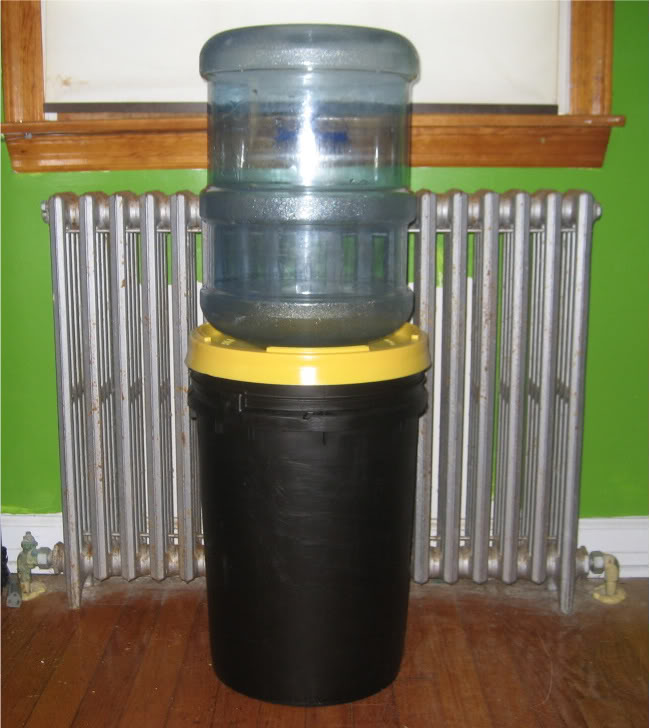
The next to be disconnected were the dosing pumps and containers. The first pump doesn't dose until 1AM, so no problem removing these for the day. Then the upper Reefkeeper came out. The only thing still connected to this were the ATO system and the pump for the carbon/gfo. This RK was mounted into the new cabinet.
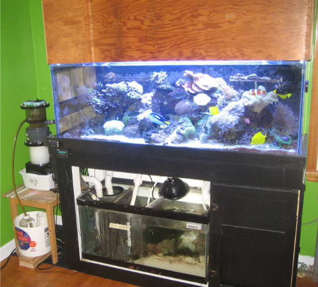
And finally the tank was shut down and the second Reefkeeper was pulled off, with a simple sendoff and farewell to the temporary equipment board. Good riddance!
I started a stopwatch because I wanted to know how long the tank would be shut down. The stand was slid into place at about 1:30-2:00PM.....a lot later than I ever would have guessed. It took 55 minutes for me to restore powerheads and return pump, and another 10 minutes to get the ReefKeeper Expansion outlet installed and heat back on. The tank had dropped 8/10 of a degree to 77.2F. Since function was restored, I now started from the top of the cabinet and worked down.
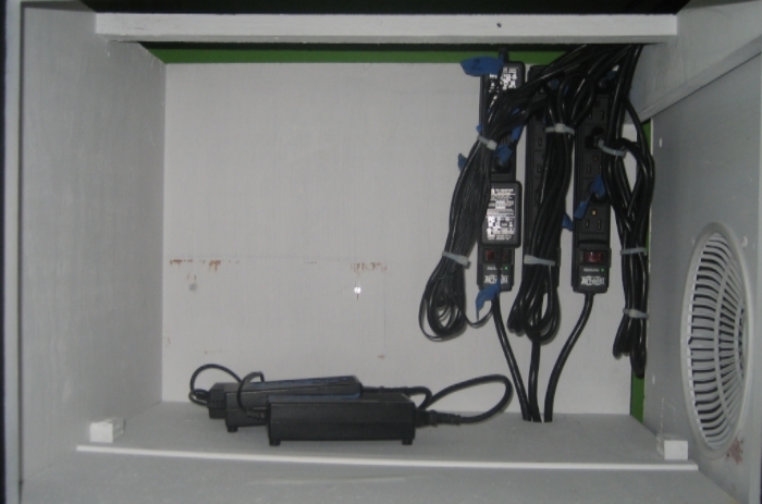
Light power strips installed, with the power supplies for the Vortechs (without the organizer.) I will be doing another organizer to accommodate the larger units.....that wasn't expected. This will all be unseen, all hidden behind a false wall.
Next was the middle section....the guts of the electronics. I pulled all remaining plugs over from the stand and plugged everything in were it belonged. I eventually want to label everything with the p-touch when I have a chance, to make it look pretty.
Two little glitches with this middle section. The wire for the MP40 needed a little cutout to get to the back side of the board. You can see the little hook shaped hole above. The second was the wire for the pH probe was rigid coming out of the connector....couldn't be bent....and hitting the shelf. This fix was to cut a grove in the shelf to accommondate the stiff wire. It's hard to see, but there is a grove there for the pH wire.
By the way, the Belly of the Beast turned out perfect. That drop-down space was enough to clear the support beam in the stand. This shot is taken in the stand of the open space for the wires to easily get into the cabinet.
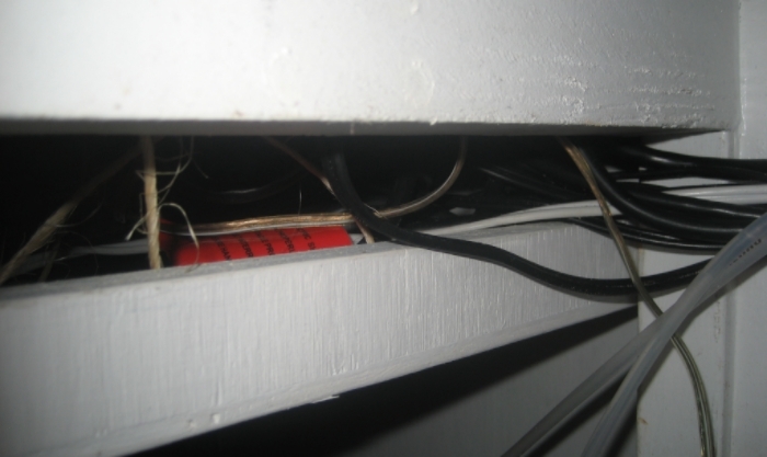
I will say that the wires in the Belly of the Beast are a mangled mess. I was hoping to have it well organized, but I was in a rush to get everything plugged in, and before you knew it, spaghetti. When I have time, I'd like to go back and straighten this up.
The bottom portion of the cabinet was easy.....dosing pumps and containers....done!

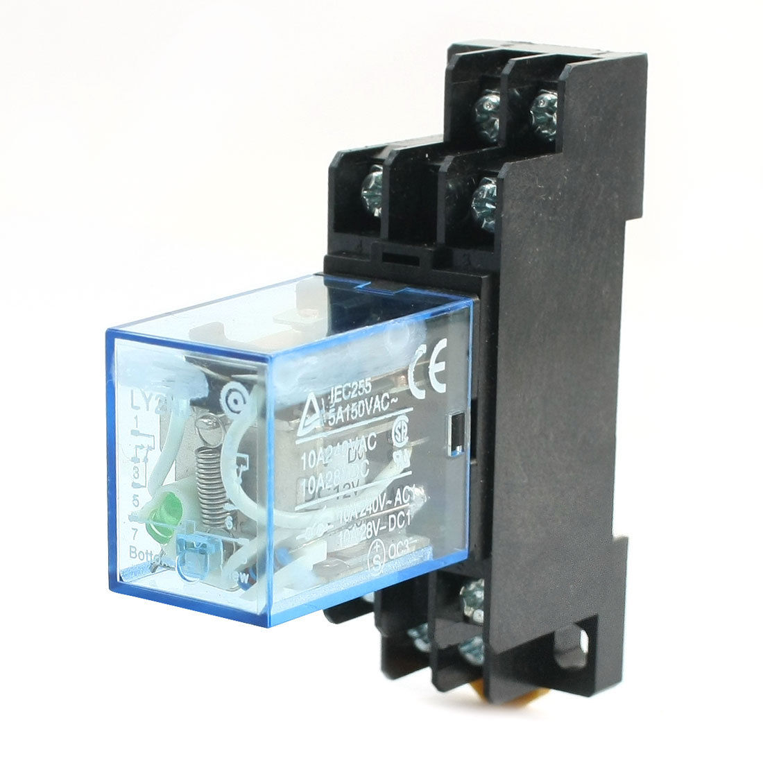
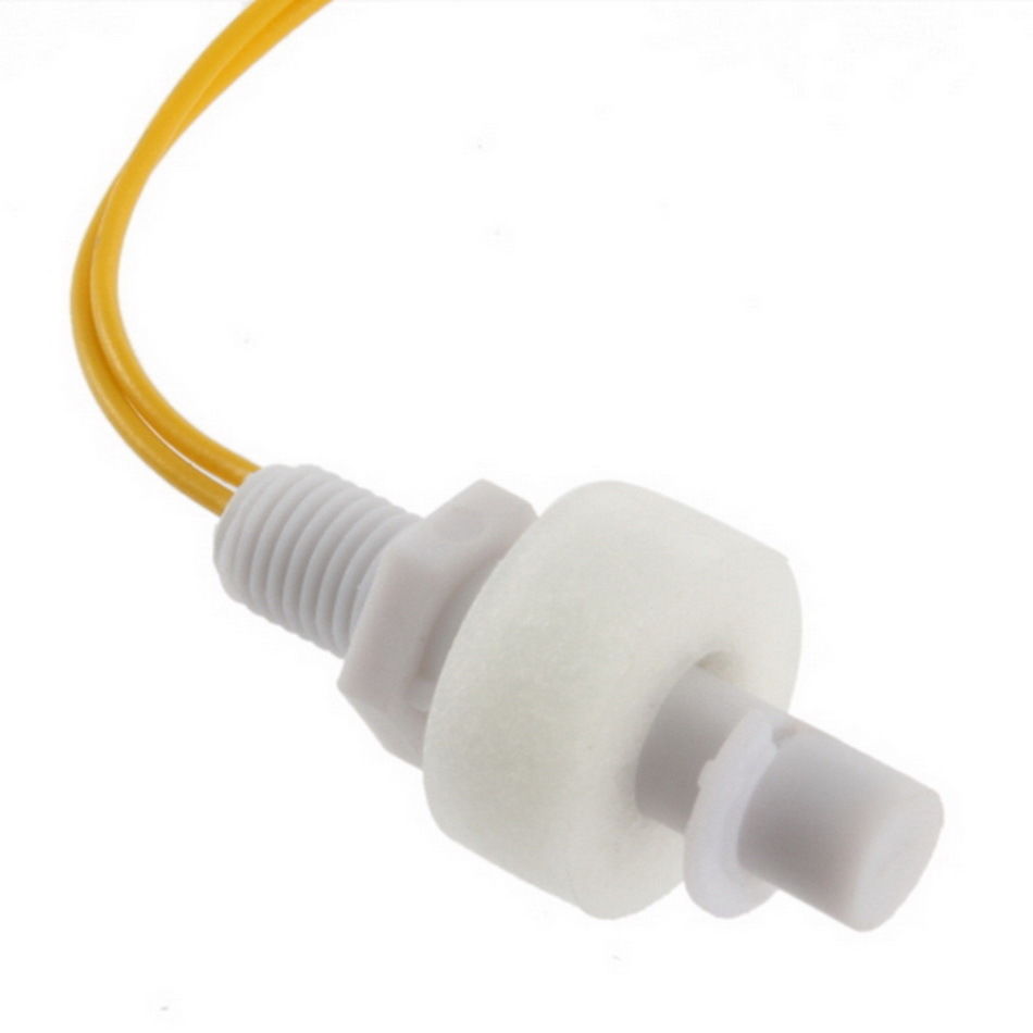
Amoungst all this caos, the UPS guy dropped off the Atman skimmer pump around 7PM. I got that put back together and found that the float switch/relay in the skimmate container wasn't working. I can only guess when the Atman shorted out, it fried the relay/float switch. I didn't want to chance a "new" skimmer with a skimmate container without the insurance of it turning off if it begins to puck. So I disconnected the container from the skimmer, and plugged off that tube. If it goes nuts, it will simply overflow the collection cup and go back into the sump. Not sure what I'll be doing about this relay/float switch thing....something for tomorrow.
And finally, here's were I am right now with this cabinet:
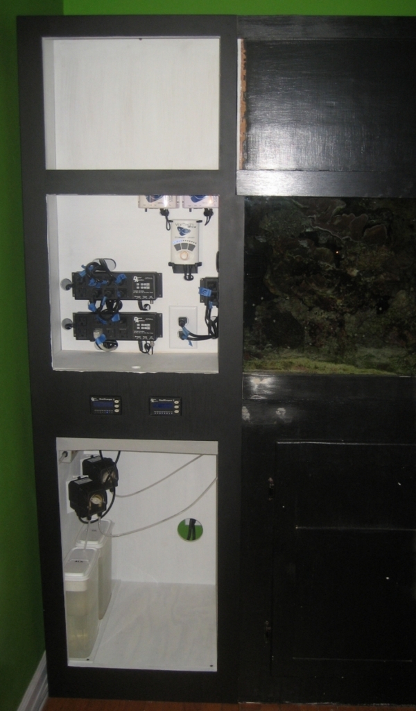

I'm still not finished. Need to do a little trim work and make the doors. WIth the false wall in the upper portion, and the light that shines through the fan cover from the canopy, I was thinking of putting a glass panel in that door frame. Got to give that additional thought. Or, maybe I can finally hang the now rusting plaque I recieved from MACNA that my wife never let me hang anywhere in the house. See'd never know it's behind that door! It's been collecting dust (and rust) in the fishroom closet since 2009.

I think I'm punch-drunk....I'm going to bed!
Wow Kevin, you weren't kidding! What a long day. I started at 7AM and didn't stop until around 10PM. The installation isn't finished, but I am! I just wished I had a Scotch to sip on while I type this.
Began the day by moving furniture and getting everything staged. Thought about those things I could disconnect and leave disconnected with minimal impact on the tank. So the first things I did were to plug all light fixtures into a power strip....directly into the wall, with now all lights ON. All these wires were moved to behind the canopy, out of the way where the cabinet was going.
Next was the MP10 power supply and controller. This powerhead is in my sump, and that would be receiving enough flow from the return pump circulation, so not a problem pulling it. Here's where I hit my first glitch. I had planned the power supply holder I built on a spare MP40 unit I had. I just assumed an Ecotech power supply, is an Ecotech power supply, is an Ecotech power supply. Well, I was wrong, but at first I thought, "no big deal." The MP10 power supply had it's feed wire offset, while the design of the holder had all feed line holes perfectly centered.....just like the power supply from the MP40 spare. I figured an easy fix, I'll just drill another hole slightly off to the side....done. I went to check the MP40 power supplies, which wasn't an easy feat, considering they were buried in the wire mess behind the equipment wall. Anyway, I reached behind and pulled one out, and here's were I now had a bigger problem. Not only was the wire offset, they were considerably bigger. So Ecotech obviously sourced different power supplies over the years. So out came the nice little holder I made to house all the power supplies. Here are three different power supplies....the one on the left is what was used to build the holder (an MP40 power supply, circa 2009), the middle one is from my MP10, and the one on the right is the current MP40 power supplies.

The next to be disconnected were the dosing pumps and containers. The first pump doesn't dose until 1AM, so no problem removing these for the day. Then the upper Reefkeeper came out. The only thing still connected to this were the ATO system and the pump for the carbon/gfo. This RK was mounted into the new cabinet.
And finally the tank was shut down and the second Reefkeeper was pulled off, with a simple sendoff and farewell to the temporary equipment board. Good riddance!

I started a stopwatch because I wanted to know how long the tank would be shut down. The stand was slid into place at about 1:30-2:00PM.....a lot later than I ever would have guessed. It took 55 minutes for me to restore powerheads and return pump, and another 10 minutes to get the ReefKeeper Expansion outlet installed and heat back on. The tank had dropped 8/10 of a degree to 77.2F. Since function was restored, I now started from the top of the cabinet and worked down.
Light power strips installed, with the power supplies for the Vortechs (without the organizer.) I will be doing another organizer to accommodate the larger units.....that wasn't expected. This will all be unseen, all hidden behind a false wall.

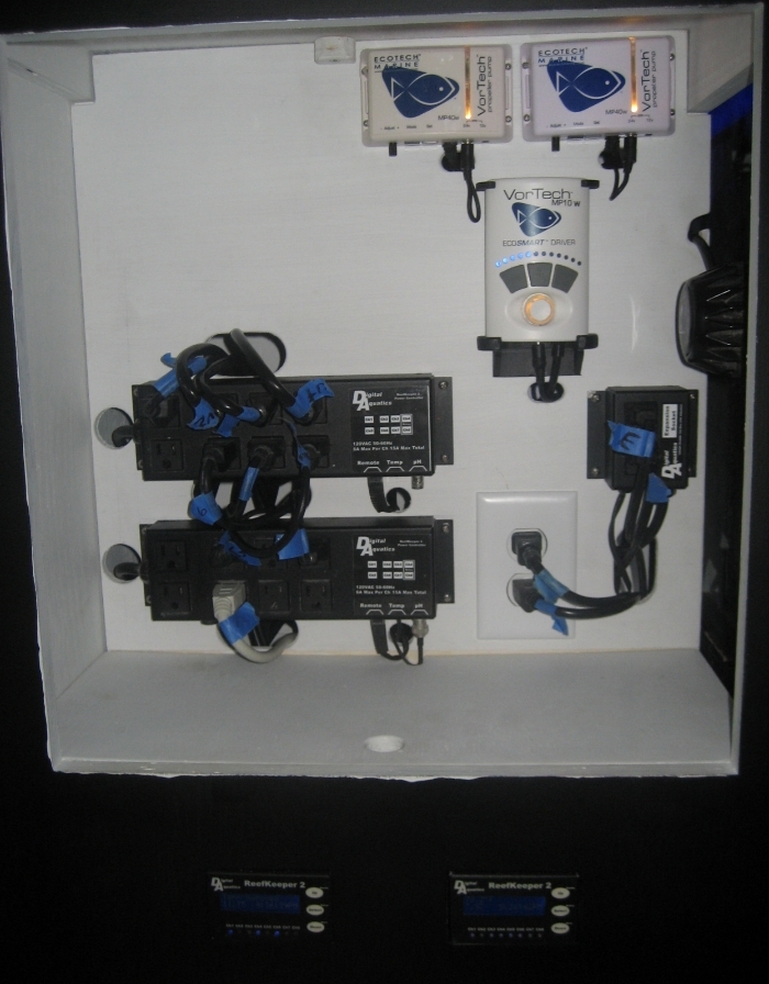
Next was the middle section....the guts of the electronics. I pulled all remaining plugs over from the stand and plugged everything in were it belonged. I eventually want to label everything with the p-touch when I have a chance, to make it look pretty.

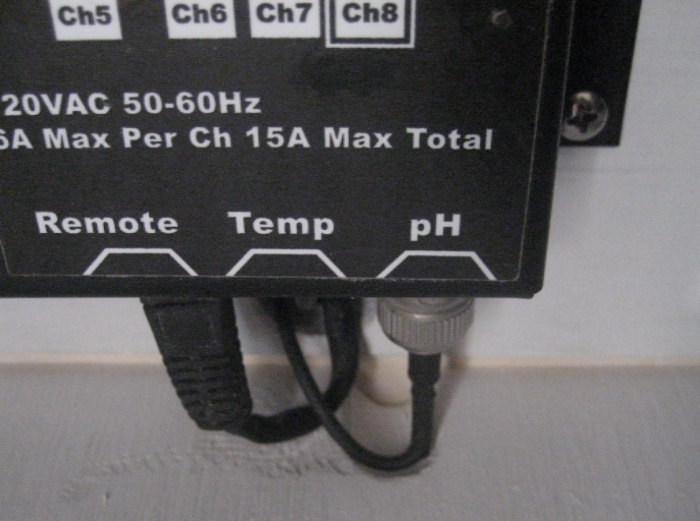
Two little glitches with this middle section. The wire for the MP40 needed a little cutout to get to the back side of the board. You can see the little hook shaped hole above. The second was the wire for the pH probe was rigid coming out of the connector....couldn't be bent....and hitting the shelf. This fix was to cut a grove in the shelf to accommondate the stiff wire. It's hard to see, but there is a grove there for the pH wire.

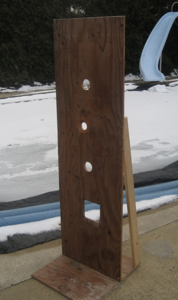
By the way, the Belly of the Beast turned out perfect. That drop-down space was enough to clear the support beam in the stand. This shot is taken in the stand of the open space for the wires to easily get into the cabinet.

I will say that the wires in the Belly of the Beast are a mangled mess. I was hoping to have it well organized, but I was in a rush to get everything plugged in, and before you knew it, spaghetti. When I have time, I'd like to go back and straighten this up.
The bottom portion of the cabinet was easy.....dosing pumps and containers....done!

Amoungst all this caos, the UPS guy dropped off the Atman skimmer pump around 7PM. I got that put back together and found that the float switch/relay in the skimmate container wasn't working. I can only guess when the Atman shorted out, it fried the relay/float switch. I didn't want to chance a "new" skimmer with a skimmate container without the insurance of it turning off if it begins to puck. So I disconnected the container from the skimmer, and plugged off that tube. If it goes nuts, it will simply overflow the collection cup and go back into the sump. Not sure what I'll be doing about this relay/float switch thing....something for tomorrow.
And finally, here's were I am right now with this cabinet:


I'm still not finished. Need to do a little trim work and make the doors. WIth the false wall in the upper portion, and the light that shines through the fan cover from the canopy, I was thinking of putting a glass panel in that door frame. Got to give that additional thought. Or, maybe I can finally hang the now rusting plaque I recieved from MACNA that my wife never let me hang anywhere in the house. See'd never know it's behind that door! It's been collecting dust (and rust) in the fishroom closet since 2009.

I think I'm punch-drunk....I'm going to bed!