Navigation
Install the app
How to install the app on iOS
Follow along with the video below to see how to install our site as a web app on your home screen.
Note: This feature may not be available in some browsers.
More options
You are using an out of date browser. It may not display this or other websites correctly.
You should upgrade or use an alternative browser.
You should upgrade or use an alternative browser.
DIY ATO on the Cheap
- Thread starter redfishbluefish
- Start date
- Tagged users None
redfishbluefish
Stay Positive, Stay Productive
View Badges
Staff member
Super Moderator
Reef Squad
Partner Member 2024
Excellence Award
Article Contributor
NJRC Member
Hospitality Award
My Tank Thread
It's "linked" in the first post.....and HERE it is again. It's listed as a "PODOY 12V DC Coil Power Relay DPDT LY2NJ HH62P-L JQX-13F 10A with PTF08A Socket Base."
And in the process of re-linking this, I've noticed the price has dropped to $3.19.
And in the process of re-linking this, I've noticed the price has dropped to $3.19.
Last edited:
redfishbluefish
Stay Positive, Stay Productive
View Badges
Staff member
Super Moderator
Reef Squad
Partner Member 2024
Excellence Award
Article Contributor
NJRC Member
Hospitality Award
My Tank Thread
It's "linked" in the first post.....and HERE it is again. It's listed as a "PODOY 12V DC Coil Power Relay DPDT LY2NJ HH62P-L JQX-13F 10A with PTF08A Socket Base."
And in the process of re-linking this, I've noticed the price has dropped to $3.19.
Great. Thank you very much for sharing.
- Joined
- Apr 28, 2014
- Messages
- 575
- Reaction score
- 279
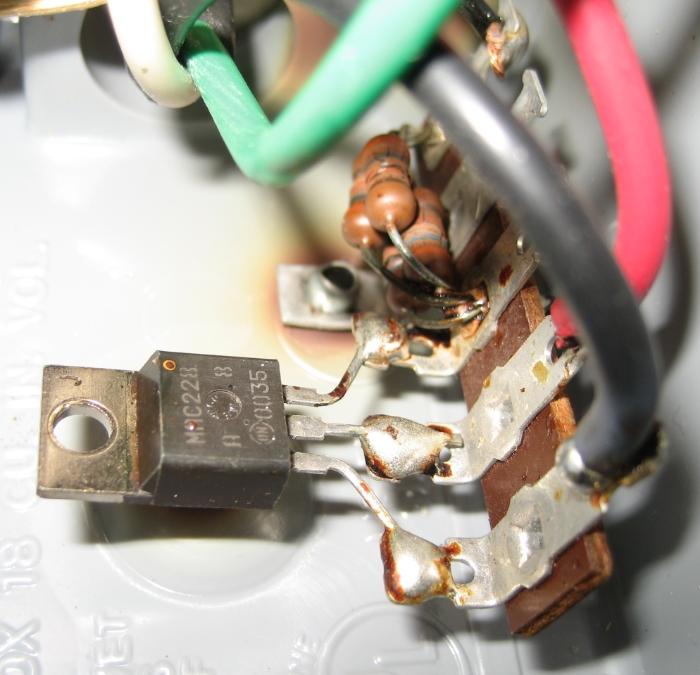
So the electronics in that box just consisted of some resistors and a triac.
The resistors were to lower the voltage at the gate of the triac as well as limit the gate current, which is also flowing through the float switch (which was seeing something close to 120V AC, can't quite make out the color bands to calculate the voltage drop). They had a bunch in parallel to prevent having to use a high power resistor.
In this case the triac is used as a switch, much like how a MOSFET can be used as a switch in DC applications. The difference being that a triac would allow conduction on the positive and negative halves of the sine wave instead of only conducting on only the positive (or negative) half wave, effectively creating a half wave rectifier.
Very simple setup, but nowhere near ideal in my mind. I much prefer running low voltage DC for the controls. It may have been slightly more efficient since there is no need for a transformer or rectification, but newer methods can draw extremely low power and are very efficient.
You had some pretty serious overheating. Glad nothing actually caught on fire.
redfishbluefish
Stay Positive, Stay Productive
View Badges
Staff member
Super Moderator
Reef Squad
Partner Member 2024
Excellence Award
Article Contributor
NJRC Member
Hospitality Award
My Tank Thread
Thanks @Skydvr for the heads-up. I actually had an electronics friend explain this thing to me as well.

He didn't give me the names (aka, Triac) but said the little black thing was a voltage regulator and the resistors lowered the voltage even more. Either way, the float switch was still being used with AC volts.
I'm happy with one I build that runs on DC.
Again, thanks for the knowledge.

He didn't give me the names (aka, Triac) but said the little black thing was a voltage regulator and the resistors lowered the voltage even more. Either way, the float switch was still being used with AC volts.
I'm happy with one I build that runs on DC.
Again, thanks for the knowledge.
Thanks Rev!
With the multimeter now working, I believe it is the numbers on the relay plug that are important, not the physical locations of the screws/connectors. So connection 7 and 8 are the coil (regardless of where they are located), even though on this plug they are the most "right" connectors. With this now known, here's my wiring diagram. Note I am using a regular wall outlet, that is mounted in my equipment cabinet, to use to plug in what I wish to control. In my case it's a skimmer. If you were making an ATO, you'd plug the reservoir pump into this outlet. Hope this diagram is understandable.
The small little trapezoid shapes are wire nuts.
This is what I was looking for. But I will like to add another float switch for my reservoir tank so the pump don't run drying case I forget to refill or anything. And maybe some LED's to indicate when is empty and if the fall safe is on. My question is. We're should I wire those extras if you know? This is an idea just to take it to another level... ☺☺By the way I'm not a electronic savior, but this project is very straight forward and I love to do things by myself, beside is cost effective.
Maybe some one could make a drawing of how it's supposed to be done...
Last edited:
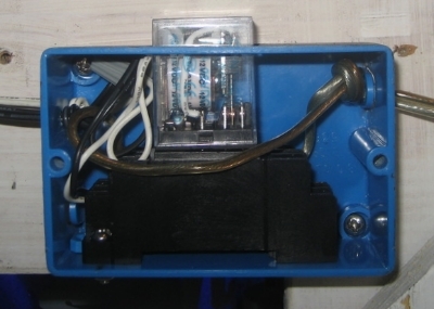
This is nearly identical to an ATO I built a year or so ago. I put the 12V power supply and relay in one half of a 2-gang box with an outlet in the other side - power came into the box from an old extension cord and the relay controlled the outlets - It was very nice to have it all self-contained. Plug the power in, make up a bracket (i bent a scrap piece of lexan I had lying around) for the float, and plug an aqualifter into the outlet on the box. when we needed to disable it for water changes, etc just unplug the pump.
This is an easy project to learn some basic electronic functions, IMO and a great alternative to overpriced off-the-shelf units!
This is an easy project to learn some basic electronic functions, IMO and a great alternative to overpriced off-the-shelf units!
Daniel@R2R
Living the Reef Life
View Badges
Staff member
Super Moderator
Reef Squad
Partner Member 2024
Excellence Award
Photo of the Month
Article Contributor
Hospitality Award
Article Administrator
Reef Pumpkin Carver
R2R Secret Santa 2023
My Tank Thread
Very informative! Thanks @redfishbluefish!
redfishbluefish
Stay Positive, Stay Productive
View Badges
Staff member
Super Moderator
Reef Squad
Partner Member 2024
Excellence Award
Article Contributor
NJRC Member
Hospitality Award
My Tank Thread
You are amazing! and I love your writing style. I am going to save this for a winter project here
Welcome @Angela Sanders to R2R! You've found the greatest reef forum.
Thanks for the very kind words. I always wonder how many DIY folks we have here and who is finding interest. Please let me know if you have any questions. Thanks again.
Thank you! Had it not been for this specific amazing piece of art, I wouldn't have resolved a 2 year old quest to wire a float switch for my skimmer cup. May you get everything you wish for this holiday season!Thanks Rev!
With the multimeter now working, I believe it is the numbers on the relay plug that are important, not the physical locations of the screws/connectors. So connection 7 and 8 are the coil (regardless of where they are located), even though on this plug they are the most "right" connectors. With this now known, here's my wiring diagram. Note I am using a regular wall outlet, that is mounted in my equipment cabinet, to use to plug in what I wish to control. In my case it's a skimmer. If you were making an ATO, you'd plug the reservoir pump into this outlet. Hope this diagram is understandable.
The small little trapezoid shapes are wire nuts.
Similar threads
- Replies
- 4
- Views
- 172
- Replies
- 4
- Views
- 115
- Replies
- 2
- Views
- 271


