use IP instead of hostname, make sure you are on the same networkYes it’s running. I connected by hdmi to a tv. I even checked that reef-pi was running. No problem there. It is some kind of connectivity issue. I see the raspberry pi on my WiFi server but I can’t ping it.
Navigation
Install the app
How to install the app on iOS
Follow along with the video below to see how to install our site as a web app on your home screen.
Note: This feature may not be available in some browsers.
More options
You are using an out of date browser. It may not display this or other websites correctly.
You should upgrade or use an alternative browser.
You should upgrade or use an alternative browser.
electrical idiot builds a controller - a reef pi build
- Thread starter Mikeneedsahobby
- Start date
- Tagged users None
- Joined
- Sep 16, 2018
- Messages
- 516
- Reaction score
- 922
Tried IP as well. Both on same network. As well as the original reef-pi. I’m actually wondering if it has to do with two raspberries running. My server shows the original with the new one’s name and shows two ip addresses for the same name. Somehow the network may be confusing them.
Last edited:
- Joined
- Sep 16, 2018
- Messages
- 516
- Reaction score
- 922
I have no idea why, but today the goblins decided to work. I was able to pull up the reef-pi UI with no problem.
I finished my first of two temp probes. It is working good. I really like these mini XLR connectors for the probe. They look and feel nice. I am a bit worried I'm going to break that thin wire going into the male side before I get it mounted. I'm sure it will be fine mounted but right now it can move too much. I'll try to be careful.
And Thank you Mike Lane for providing the pigtails to the hat! As much as I now hate the pin connector crimping for the power supply I was so glad to have ready made connectors for everything else!
Happy!
- Joined
- Sep 16, 2018
- Messages
- 516
- Reaction score
- 922
And two temperature probes working! They are within 0.2 F of each other or less and about 0.2 and 0.4 from the trolls temperature probe.
Close enough for me!
Now on to controlling power.

Close enough for me!
Now on to controlling power.
Love these mini xlr connectors
- Joined
- Sep 16, 2018
- Messages
- 516
- Reaction score
- 922
*@*!**! the gremlins were FEISTY tonight! I forced them back into service with a burning hot piece of pointed steel!
It started off bad from the start. Gremlins wouldn't connect to other computers again. I started scouring the web and found others complaining about the same thing. Words like routing port 3389 and forcing WLAN0, and setting a static IP. Instead of all this I reset my router. Gremlins came up after the router rebooted and so far has come back up 4 or 5 times in a row. This problem is definitely a network issue on my router and probably unique to me in the reef-pi world. (but not raspberry pi world)
So with Gremlins back up on my laptop, I turned my focus to controlling the DJ SRP 8 power outlets. *&@*! more pin connectors. I am getting a little better with these things. But they suck! I had a few pull out after putting the cable together. I used the layout posted above from Mike Lane and a post from his build thread on the pin to channels for the SRP8. A couple hours later I had this connector from the PI-Hat to a male DB9 panel mount connector.

In my glee I took a quick break to get my daughter's hair ready for soccer practice.
I connected everything together that I had built so far. I was happy because I thought I had a working heater controller with two temp probes and eight controllable outlets. I snapped this photo of everything so far while still holding a smile.
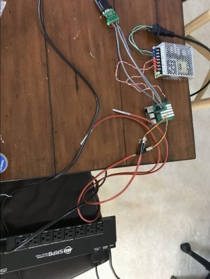
Messy but I didn't care.
....
The gremlins did. They don't like messy photos. All of that careful checking of wires and where they go didn't work. Ch 2 was controlled by outlet 3. 1 and 8 were swapped. 5 was on 4. 4 was on 6. And 5 didn't work!!!
I knew I must have wired something wrong. I spent the next 3 hours looking at the stuff Mike Lane posted. Reading the schematic on github. Tracking wires with my multimeter. Watching 12V voltage go on and off when I click stuff on the reef-pi. I eventually gave in and renamed everything in reef pi so when I clicked a button the expected plug would come on. (And fixed about 3 pins I pulled out accidentally playing with stuff). But channel 5 would not work. I could hear the relay clicking. It sounded a little quieter than the others.
I pulled the SRJ 8 apart and started probing things with my multimeter. No 120V was making it past the relay. Then I saw this under the circuit board. Multimeter agreed with the ugliness I saw and reported no continuity between 120V in and this joint.
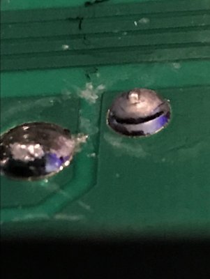
And I went for my burning hot piece of pointed steel. I held my soldering iron to the broken joint until the solder sucked in and looked good. Multimeter gave me a happy beep for my work.
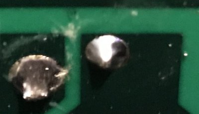
Thanks American DJ ! I needed the soldering practice. Besides I kind of like soldering. I get to make smoke!
8 controllable outlets functioning as expected. Two temperature probes providing inputs to make decisions. All gremlins following orders again!
Next: figure out what a Mosfet is....
It started off bad from the start. Gremlins wouldn't connect to other computers again. I started scouring the web and found others complaining about the same thing. Words like routing port 3389 and forcing WLAN0, and setting a static IP. Instead of all this I reset my router. Gremlins came up after the router rebooted and so far has come back up 4 or 5 times in a row. This problem is definitely a network issue on my router and probably unique to me in the reef-pi world. (but not raspberry pi world)
So with Gremlins back up on my laptop, I turned my focus to controlling the DJ SRP 8 power outlets. *&@*! more pin connectors. I am getting a little better with these things. But they suck! I had a few pull out after putting the cable together. I used the layout posted above from Mike Lane and a post from his build thread on the pin to channels for the SRP8. A couple hours later I had this connector from the PI-Hat to a male DB9 panel mount connector.

In my glee I took a quick break to get my daughter's hair ready for soccer practice.

I connected everything together that I had built so far. I was happy because I thought I had a working heater controller with two temp probes and eight controllable outlets. I snapped this photo of everything so far while still holding a smile.

Messy but I didn't care.
....
The gremlins did. They don't like messy photos. All of that careful checking of wires and where they go didn't work. Ch 2 was controlled by outlet 3. 1 and 8 were swapped. 5 was on 4. 4 was on 6. And 5 didn't work!!!
I knew I must have wired something wrong. I spent the next 3 hours looking at the stuff Mike Lane posted. Reading the schematic on github. Tracking wires with my multimeter. Watching 12V voltage go on and off when I click stuff on the reef-pi. I eventually gave in and renamed everything in reef pi so when I clicked a button the expected plug would come on. (And fixed about 3 pins I pulled out accidentally playing with stuff). But channel 5 would not work. I could hear the relay clicking. It sounded a little quieter than the others.
I pulled the SRJ 8 apart and started probing things with my multimeter. No 120V was making it past the relay. Then I saw this under the circuit board. Multimeter agreed with the ugliness I saw and reported no continuity between 120V in and this joint.

And I went for my burning hot piece of pointed steel. I held my soldering iron to the broken joint until the solder sucked in and looked good. Multimeter gave me a happy beep for my work.

Thanks American DJ ! I needed the soldering practice. Besides I kind of like soldering. I get to make smoke!
8 controllable outlets functioning as expected. Two temperature probes providing inputs to make decisions. All gremlins following orders again!
Next: figure out what a Mosfet is....
Last edited:
- Joined
- Aug 11, 2018
- Messages
- 677
- Reaction score
- 1,123
Nice job with the ADJ diagnosis and repair! I've seen at least 1 or 2 other people complain of similar problems with it. It's definitely a product to open and inspect before putting into use.*@*!**! the gremlins were FEISTY tonight! I forced them back into service with a burning hot piece of pointed steel!
It started off bad from the start. Gremlins wouldn't connect to other computers again. I started scouring the web and found others complaining about the same thing. Words like routing port 3389 and forcing WLAN0, and setting a static IP. Instead of all this I reset my router. Gremlins came up after the router rebooted and so far has come back up 4 or 5 times in a row. This problem is definitely a network issue on my router and probably unique to me in the reef-pi world. (but not raspberry pi world)
So with Gremlins back up on my laptop, I turned my focus to controlling the DJ SRP 8 power outlets. *&@*! more pin connectors. I am getting a little better with these things. But they suck! I had a few pull out after putting the cable together. I used the layout posted above from Mike Lane and a post from his build thread on the pin to channels for the SRP8. A couple hours later I had this connector from the PI-Hat to a male DB9 panel mount connector.

In my glee I took a quick break to get my daughter's hair ready for soccer practice.
I connected everything together that I had built so far. I was happy because I thought I had a working heater controller with two temp probes and eight controllable outlets. I snapped this photo of everything so far while still holding a smile.

Messy but I didn't care.
....
The gremlins did. They don't like messy photos. All of that careful checking of wires and where they go didn't work. Ch 2 was controlled by outlet 3. 1 and 8 were swapped. 5 was on 4. 4 was on 6. And 5 didn't work!!!
I knew I must have wired something wrong. I spent the next 3 hours looking at the stuff Mike Lane posted. Reading the schematic on github. Tracking wires with my multimeter. Watching 12V voltage go on and off when I click stuff on the reef-pi. I eventually gave in and renamed everything in reef pi so when I clicked a button the expected plug would come on. (And fixed about 3 pins I pulled out accidentally playing with stuff). But channel 5 would not work. I could hear the relay clicking. It sounded a little quieter than the others.
I pulled the SRJ 8 apart and started probing things with my multimeter. No 120V was making it past the relay. Then I saw this under the circuit board. Multimeter agreed with the ugliness I saw and reported no continuity between 120V in and this joint.

And I went for my burning hot piece of pointed steel. I held my soldering iron to the broken joint until the solder sucked in and looked good. Multimeter gave me a happy beep for my work.

Thanks American DJ ! I needed the soldering practice. Besides I kind of like soldering. I get to make smoke!
8 controllable outlets functioning as expected. Two temperature probes providing inputs to make decisions. All gremlins following orders again!
Next: figure out what a Mosfet is....
- Joined
- Dec 16, 2018
- Messages
- 1,189
- Reaction score
- 2,826
Good job, and you are getting good at finding and banishing bad gremlins!*@*!**! the gremlins were FEISTY tonight! I forced them back into service with a burning hot piece of pointed steel!
It started off bad from the start. Gremlins wouldn't connect to other computers again. I started scouring the web and found others complaining about the same thing. Words like routing port 3389 and forcing WLAN0, and setting a static IP. Instead of all this I reset my router. Gremlins came up after the router rebooted and so far has come back up 4 or 5 times in a row. This problem is definitely a network issue on my router and probably unique to me in the reef-pi world. (but not raspberry pi world)
So with Gremlins back up on my laptop, I turned my focus to controlling the DJ SRP 8 power outlets. *&@*! more pin connectors. I am getting a little better with these things. But they suck! I had a few pull out after putting the cable together. I used the layout posted above from Mike Lane and a post from his build thread on the pin to channels for the SRP8. A couple hours later I had this connector from the PI-Hat to a male DB9 panel mount connector.

In my glee I took a quick break to get my daughter's hair ready for soccer practice.
I connected everything together that I had built so far. I was happy because I thought I had a working heater controller with two temp probes and eight controllable outlets. I snapped this photo of everything so far while still holding a smile.

Messy but I didn't care.
....
The gremlins did. They don't like messy photos. All of that careful checking of wires and where they go didn't work. Ch 2 was controlled by outlet 3. 1 and 8 were swapped. 5 was on 4. 4 was on 6. And 5 didn't work!!!
I knew I must have wired something wrong. I spent the next 3 hours looking at the stuff Mike Lane posted. Reading the schematic on github. Tracking wires with my multimeter. Watching 12V voltage go on and off when I click stuff on the reef-pi. I eventually gave in and renamed everything in reef pi so when I clicked a button the expected plug would come on. (And fixed about 3 pins I pulled out accidentally playing with stuff). But channel 5 would not work. I could hear the relay clicking. It sounded a little quieter than the others.
I pulled the SRJ 8 apart and started probing things with my multimeter. No 120V was making it past the relay. Then I saw this under the circuit board. Multimeter agreed with the ugliness I saw and reported no continuity between 120V in and this joint.

And I went for my burning hot piece of pointed steel. I held my soldering iron to the broken joint until the solder sucked in and looked good. Multimeter gave me a happy beep for my work.

Thanks American DJ ! I needed the soldering practice. Besides I kind of like soldering. I get to make smoke!
8 controllable outlets functioning as expected. Two temperature probes providing inputs to make decisions. All gremlins following orders again!
Next: figure out what a Mosfet is....
A mosfet is just a DC switch, with the dfrobot boards, all the figuring out is already done but in simple terms the mosfet allows power thru when the gatekeeper gremlin gets the signal, he hollers "open the gate" and they gremlims open it and power can flow. When he gets the opposite signal he hollers "close the gate" and power flow quits. Because this is a PWM signal, these gremlins have to be very fast.
Do you have your dfrobot boards yet?
- Joined
- Sep 16, 2018
- Messages
- 516
- Reaction score
- 922
Yes, I have them. And I was joking with that comment. It is just my way of saying what I am doing next.Good job, and you are getting good at finding and banishing bad gremlins!
A mosfet is just a DC switch, with the dfrobot boards, all the figuring out is already done but in simple terms the mosfet allows power thru when the gatekeeper gremlin gets the signal, he hollers "open the gate" and they gremlims open it and power can flow. When he gets the opposite signal he hollers "close the gate" and power flow quits. Because this is a PWM signal, these gremlins have to be very fast.
Do you have your dfrobot boards yet?
I have already read what you showed me before. I know what the 4 pins do and the wiring circuit with the mosfets, but I don't know what pin is which. I'll probably probe with my multimeter to figure it out. I'm also wondering if I should by a new connector and completely replace the one on the fixture or buy the $16 timer to take a connector.
oh and I have the mosfet's already.
- Joined
- Dec 16, 2018
- Messages
- 1,189
- Reaction score
- 2,826
I looked online for days and could only find something close but something was always different...the keyway, the size by a millimeter. In the end I cut the cords off my timers(i already had them) such that I could solder them back onto the timers if need be.@Bigtrout , Did you figure what type of connector this is or should I buy the timer for the light just for the connector?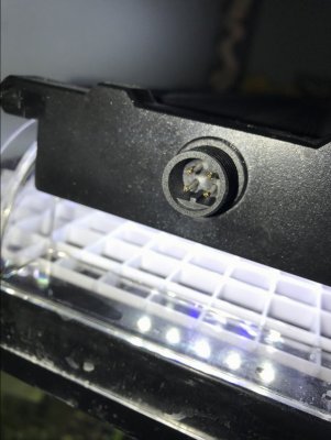
Turns out that the PWM control is great, I wont need the timers, nor do I want to use them.
Since you have only one light it makes it easy. The cord on the timer is about 16 inches, I bought a piece of 18 AWG 4 conductor with a dark gray insulation from home depot and spliced and heatshrinked that to the cord from the timer and ran that to my reef pi...easy and clean looking!
Next time i get under my stand and open my pi case I need to get some pics for you of the hookups etc.
Last edited:
Yes, this is the third case I am aware ofNice job with the ADJ diagnosis and repair! I've seen at least 1 or 2 other people complain of similar problems with it. It's definitely a product to open and inspect before putting into use.
- Joined
- Sep 16, 2018
- Messages
- 516
- Reaction score
- 922
Ok, Ordering a timer.I looked online for days and could only find something close but something was always different...the keyway, the size by a millimeter. In the end I cut the cords off my timers(i already had them) such that I could solder them back onto the timers if need be.
Turns out that the PWM control is great, I wont need the timers, nor do I want to use them.
Since you have only one light it makes it easy. The cord on the timer is about 16 inches, I bought a piece of 18 AWG 4 conductor with a dark gray insulation from home depot and spliced and heatshrinked that to the cord from the timer and ran that to my reef pi...easy and clean looking!
- Joined
- Sep 16, 2018
- Messages
- 516
- Reaction score
- 922
@Bigtrout
Is this the circuit for the lights?
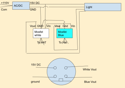
and the P mosfets have 3 wire connectors. Each light connector on the hat is 4 pins. 1 ground and 3 others. Do I connect with the left 3 connectors to pick up ground and 2 other pins or am I missing something.
Is this the circuit for the lights?

and the P mosfets have 3 wire connectors. Each light connector on the hat is 4 pins. 1 ground and 3 others. Do I connect with the left 3 connectors to pick up ground and 2 other pins or am I missing something.
Last edited:
- Joined
- Dec 16, 2018
- Messages
- 1,189
- Reaction score
- 2,826
Looking good, you got it!@Bigtrout
Is this the circuit for the lights?

and the P mosfets have 3 wire connectors. Each light connector on the hat is 4 pins. 1 ground and 3 others. Do I connect with the left 3 connectors to pick up ground and 2 other pins or am I missing something.
- Joined
- Dec 16, 2018
- Messages
- 1,189
- Reaction score
- 2,826
You only use 2 pins on each dfrobot board input, signal and ground...the other isnt even connected on the board. I took ground and 2 pins on mikes hat and split the ground between both board inputs and each pin went to its own dfrobot board@Bigtrout
Is this the circuit for the lights?

and the P mosfets have 3 wire connectors. Each light connector on the hat is 4 pins. 1 ground and 3 others. Do I connect with the left 3 connectors to pick up ground and 2 other pins or am I missing something.
- Joined
- Dec 16, 2018
- Messages
- 1,189
- Reaction score
- 2,826
Your circuit is correct, only you dont have to mess with the light power supply, you only need to use the 4 pin connector. Inside the light they already jumper the 15V and Ground from the power supply to that connector.

- Joined
- Sep 16, 2018
- Messages
- 516
- Reaction score
- 922
It’s becoming clear now! Thank you for the help!Your circuit is correct, only you dont have to mess with the light power supply, you only need to use the 4 pin connector. Inside the light they already jumper the 15V and Ground from the power supply to that connector.

The power supply isn’t touched at all. The 4 pin will provide the 15v and ground to the mosfet through a jumper in the light from the power supply. The other two wires Bring back the blue and white signal.
This is much better then how I had it drawn!
Similar threads
- Replies
- 3
- Views
- 105
- Replies
- 8
- Views
- 168


