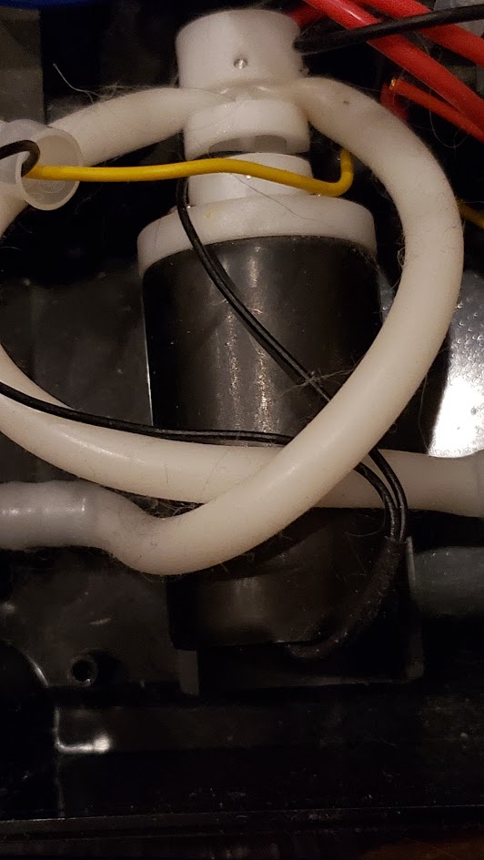
Equipment Review: Aquarium Engineering ACR (Automatic Calcium Reactor)

Dennis Cartier

Valuable Member
View Badges
Joined
Aug 25, 2016
Messages
1,950
Reaction score
2,388
Location
Brampton, Ontario
Rating - 0%
0   0   0
Quick question about a used ACR I bought a while back and am going to set up. Is the pic correct ?? Thanks !
B51FB168-6520-4ABD-ADDC-36CBBB168631.jpeg
That looks correct to me.

If you are using the factory controller with your ACR, it would be a good idea to open up the valve box and check for signs of water ingress and corrosion.

If the controller checks out, you should install an external CO2 check valve between the ACR and the controller. The controller has an internal one, but they tend not to work, so an external one is suggested.
 
Last edited:

Cali9dub

Well-Known Member
View Badges
Joined
Aug 18, 2013
Messages
943
Reaction score
393
Location
Cape Coral, Florida
Rating - 100%
1   0   0
That looks correct to me.

If you are using the factory controller with your ACR, it would be a good idea to open up the valve box and check for signs of water ingress and corrosion.

If the controller checks out, you should install an external CO2 check valve between the ACR and the controller. The controller has an internal one, but they tend not to work, so an external one is suggested.
I have an external co2 check valve and I have a controller with a peristaltic pump on the outside not any pinch valve or anything liquid inside the controller. The tubing used in that peristaltic pump head looks suspect and I’ll be changing it out for the traditional tan colored hose intended for persistaltic pumps. Fingers crossed everything works out and I can figure it all out because the reactor itself appears well built.
 

Dennis Cartier

Valuable Member
View Badges
Joined
Aug 25, 2016
Messages
1,950
Reaction score
2,388
Location
Brampton, Ontario
Rating - 0%
0   0   0
I have an external co2 check valve and I have a controller with a peristaltic pump on the outside not any pinch valve or anything liquid inside the controller. The tubing used in that peristaltic pump head looks suspect and I’ll be changing it out for the traditional tan colored hose intended for persistaltic pumps. Fingers crossed everything works out and I can figure it all out because the reactor itself appears well built.
Ok, good. Post any questions and I am sure we can help you get it running. Yes, the ACR reactors are very well built. It's too bad that they are no longer being made.
 

Cali9dub

Well-Known Member
View Badges
Joined
Aug 18, 2013
Messages
943
Reaction score
393
Location
Cape Coral, Florida
Rating - 100%
1   0   0
Ok, good. Post any questions and I am sure we can help you get it running. Yes, the ACR reactors are very well built. It's too bad that they are no longer being made.
Here is the controller I have. I plan on having a couple peristaltic pumps for swap out in case ( they are cheap on alix. Probably get a solenoid or 2 as well just so I’m set for many years.
900C11C2-327E-4B8E-A007-E5DDC4F8B199.jpeg
 

Dennis Cartier

Valuable Member
View Badges
Joined
Aug 25, 2016
Messages
1,950
Reaction score
2,388
Location
Brampton, Ontario
Rating - 0%
0   0   0
Here is the controller I have. I plan on having a couple peristaltic pumps for swap out in case ( they are cheap on alix. Probably get a solenoid or 2 as well just so I’m set for many years.
900C11C2-327E-4B8E-A007-E5DDC4F8B199.jpeg
Hmm, it looks like you have a different variation of the peristaltic pump version of controller. Previous ones had the pump on the front, and used a PWM speed controller with a DC gear motor. Yours uses the older style duty cycle controller, so it may be stepper based instead.

I agree changing out that silicone tubing for the longer life Pharmed tubing would be best. I believe it takes LS17 sized tubing.
 

Cali9dub

Well-Known Member
View Badges
Joined
Aug 18, 2013
Messages
943
Reaction score
393
Location
Cape Coral, Florida
Rating - 100%
1   0   0
Hmm, it looks like you have a different variation of the peristaltic pump version of controller. Previous ones had the pump on the front, and used a PWM speed controller with a DC gear motor. Yours uses the older style duty cycle controller, so it may be stepper based instead.

I agree changing out that silicone tubing for the longer life Pharmed tubing would be best. I believe it takes LS17 sized tubing.
Here are the innards. Looks like on the 12v pump it shows 6.4mm x 9.6mm tubing. Doesn’t appear to be a stepper motor. Just pumps effluent for “x” amount of time on and “x”amount of time off. Not sure how it knows to open the CO2 solenoid.
054A5F1A-F726-4577-BDDA-498E1B63E13F.jpeg
 

Dennis Cartier

Valuable Member
View Badges
Joined
Aug 25, 2016
Messages
1,950
Reaction score
2,388
Location
Brampton, Ontario
Rating - 0%
0   0   0
Here are the innards. Looks like on the 12v pump it shows 6.4mm x 9.6mm tubing. Doesn’t appear to be a stepper motor. Just pumps effluent for “x” amount of time on and “x”amount of time off. Not sure how it knows to open the CO2 solenoid.
054A5F1A-F726-4577-BDDA-498E1B63E13F.jpeg
Hmm, OK, another variation on the peristaltic pump version. Instead of controlling the speed of the peristaltic you are controlling the duty cycle. I am guessing this is probably a transitional version between the pinch valve style and the peristaltic pump style, with the version using the PWM Speed controller being the newest and last version made.

The cable exiting the box is your float switch cable. That plugs into the ACR and directly controls the solenoid for opening and closing.

Pretty straight forward. Just make sure to install your own check valve between the controller and your ACR and you should be good to go.
 

Cali9dub

Well-Known Member
View Badges
Joined
Aug 18, 2013
Messages
943
Reaction score
393
Location
Cape Coral, Florida
Rating - 100%
1   0   0
Hmm, OK, another variation on the peristaltic pump version. Instead of controlling the speed of the peristaltic you are controlling the duty cycle. I am guessing this is probably a transitional version between the pinch valve style and the peristaltic pump style, with the version using the PWM Speed controller being the newest and last version made.

The cable exiting the box is your float switch cable. That plugs into the ACR and directly controls the solenoid for opening and closing.

Pretty straight forward. Just make sure to install your own check valve between the controller and your ACR and you should be good to go.
I have a check valve on the CO2 out side of the controller as close to the reactor as I could. Not sure what a good check valve is. I’m using the one from the Carbon Doser regulator. Also tested the controller (not co2 yet) but man that peristaltic pump is LOUD !!
 
Last edited:

Dennis Cartier

Valuable Member
View Badges
Joined
Aug 25, 2016
Messages
1,950
Reaction score
2,388
Location
Brampton, Ontario
Rating - 0%
0   0   0
I have a check valve on the CO2 out side of the controller as close to the reactor as I could. Not sure what a good check valve is. I’m using the one from the Carbon Doser regulator. Also tested the controller (not co2 yet) but man that peristaltic pump is LOUD !!
The Carbon Doser check valve will be great for this purpose. You just want one that is intended for CO2, which the Carbon Doser version is, and is of decent quality.

Yes, I expect the DC motor driving that pump to be LOUD. The control method being used drives it at 100% while it is running. The second version of this controller, used a PWM speed controller to allow the motor to be driven at a lower speed and probably a lot quieter.

The longevity of the DC motor is the weak point in this controller design. Using a DC motor in a continuous duty application like a CaRx is generally not recommended.

That being said, if you can live with the noise, then I am sure it will be sufficient for the foreseeable.

... and if it does become an issue, you always have the community supported version to fall back on.


Dennis Cartier

Valuable Member
View Badges
Joined
Aug 25, 2016
Messages
1,950
Reaction score
2,388
Location
Brampton, Ontario
Rating - 0%
0   0   0
What pinch valves did he use? Are they reasonably priced?
He used a couple of different ones. I looked at the version in my old factory controller but it has no markings on it. Some of the later controllers had a smaller pinch valve for the CO2.
 

Dennis Cartier

Valuable Member
View Badges
Joined
Aug 25, 2016
Messages
1,950
Reaction score
2,388
Location
Brampton, Ontario
Rating - 0%
0   0   0
I found it using Google Lens. Update: The trident valve is slightly different. The cable exits through the side of the solenoid, whereas the AE valve exits at the end seam. The AE also has a center hole in the end plate, along with the 4 holes. The Trident version has no center hole.

 
Last edited:

second_decimal

Community Member
View Badges
Joined
Nov 14, 2019
Messages
66
Reaction score
30
Rating - 0%
0   0   0
I recently developed a leak in this part. Looks like it was 3D printed and it’s starting to sweat badly enough to puddle. Is this something some one has laying around? Thanks.

edit: I have the 2 port version with feed intake separate elsewhere.
1674074320826.jpeg
96DE581F-42EC-4F78-8E11-192110845858.jpeg A62410B1-E19B-496B-8C65-5CC1EC9CAE94.jpeg
 

Cali9dub

Well-Known Member
View Badges
Joined
Aug 18, 2013
Messages
943
Reaction score
393
Location
Cape Coral, Florida
Rating - 100%
1   0   0
Since Bill Dong left everyone high and dry he should at least post parts lists, sourcing and 3D printed files so people can do their own repairs. He obviously isn’t going to.
 

second_decimal

Community Member
View Badges
Joined
Nov 14, 2019
Messages
66
Reaction score
30
Rating - 0%
0   0   0
Oof.. I was hoping someone had a spare or whatever laying around. If I don’t find an exact match, just matching the union fittings will be a pia if that’s even possible at all.
 

Dennis Cartier

Valuable Member
View Badges
Joined
Aug 25, 2016
Messages
1,950
Reaction score
2,388
Location
Brampton, Ontario
Rating - 0%
0   0   0
Hmm, my suggestion for dealing with this is to collect whatever info we can off the fitting he used, to identify the brand. It looks like schedule 80 grey fittings. Hopefully he stuck to 1 supplier, though I am always surprised by how many variations there are in the production run of reactors he built.

Once we have found a source of the fittings, purchasing a matching union and then make a new part using a CPR venturi like he originally used before the 3D printed parts started being incorporated. The viability of this plan would depend on how long the part we are replacing is. The venturi can be cut down and shortened, but can't easily be lengthened.

I am sure we could come up with another 3D model from scratch, but would suggest moving to the molded CPR part instead.

Is their a logo or name or part number on the union fitting? What is the distance in millimeters between the edge of the top and bottom union (the length of the visible blue 3D part)?

The fact that the leak is appearing as a line is a bit concerning as it suggests a weakness along the whole circumference. I agree it looks like a layer is in the process of detaching. If this is progressively getting worse, you may end up with a catastrophic failure at some point.

Ironically, this is something I have been contemplating recently, the possibility of 3D parts being susceptible to salt creep and leaking through the surface. The 3D printed venturi part in the ACR was one of my examples where this had been done successfully.
 

Looking for the spotlight: Do your fish notice the lighting in your reef tank?

  • My fish seem to regularly respond to the lighting in my reef tank.

    Votes: 94 75.8%
  • My fish seem to occasionally respond to the lighting in my tank.

    Votes: 15 12.1%
  • My fish seem to rarely respond to the lighting in my tank.

    Votes: 8 6.5%
  • My fish seem to never respond to the lighting in my tank.

    Votes: 1 0.8%
  • I don’t pay enough attention to my fish to notice if they respond to the lighting.

    Votes: 2 1.6%
  • I don’t have any fish in my tank.

    Votes: 2 1.6%
  • Other.

    Votes: 2 1.6%
Back
Top