

This thread is provide a walk through for building an automatic calcium reactor controller for the Aquarium Engineering ACR line of CaRx's, though it will work with other CaRx's, like my DIY (Schuran) Jetstream stlye automatic Calcium Reactor
History
The AE ACR is a line of CaRx that use a float switch to regulate the addition of CO2 in a similar way to the Dastaco and Deltec units. This allows them to operate in saturation mode, dissolving CO2 into the water column until the saturation point is achieved, and no more CO2 will dissolve. This eliminates the need for a pH probe and bubble counter and makes them automatic. The only adjustment required of the user is how much flow through the CaRx to set the supplementation level.
AE recently ceased operations and the ACR units have been orphaned. As well the factory controllers have an abysmal track record of failing after about a year of operation. When I experienced this firsthand, I decided to design a replacement controller that addressed the shortcomings of the factory version.
The v1 design just used a Clippard EV Mouse valve inline with the float switch. This is the same valve used in the Carbon Doser and in my CO2 Tank Auto Switcher.
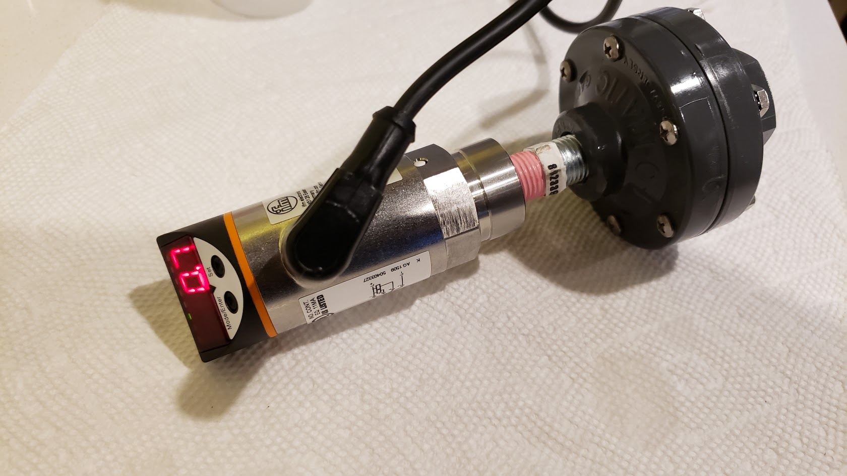
The v2 design added an IFM pressure sensor to provide feedback on the pressure the CaRx was running at. I found the pressure sensors by chance while searching Ebay for a pressure switch for my phosphate reactor. These are pressure sensors, used widely in the automation industry, and offer programmable outputs, and extreme reliability.
The v3 design added auto venting to the controller.
The v4 design is the one being discussed here.
The v4 Controller
For the v4 model, the method of operation is all new, and does not operate like the factory controller at all. All the previous designs, followed the factory pattern of feeding the CaRx from a dedicated pump or manifold, metering the effluent out using a peristaltic pump, with the float switch directly controlling the CO2 valve. The v2 and v3 models used an IFM pressure sensor to limit the pressure that would be allowed before closing the Clippard valve and preventing the reactor from going over a set pressure.
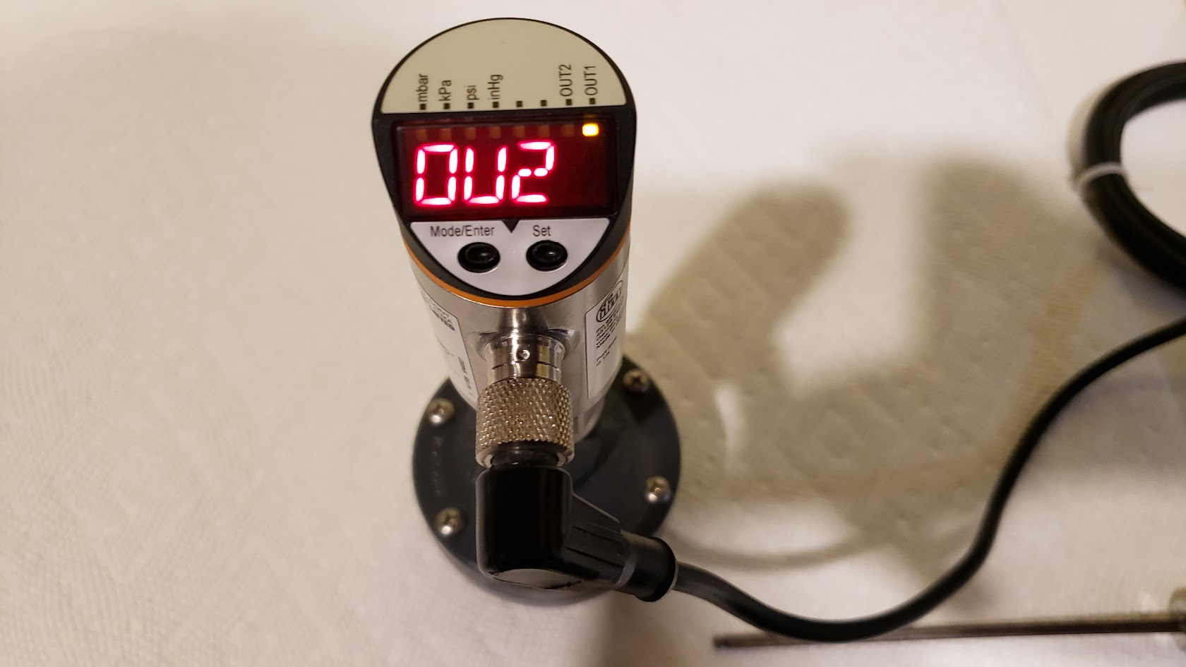
For the v4, we are moving to an IFM pressure sensor that offers 2 outputs. This allows us to use one output to control the addition of CO2, and the second output controls the addition of feed water using a peristaltic pump. This makes the CaRx into a sealed pressure vessel, and allows for the operation of the CaRx to be based on pressure changes. This brings some interesting benefits. By raising the pressure above atmospheric, we can raise the CO2 saturation level of the water column, allowing higher flow rates while maintaining the effluent strength. By allowing the operating pressure to be adjustable, we can adjust how strong the effluent is. This also allows us to affect how fast supplementation can be provided.
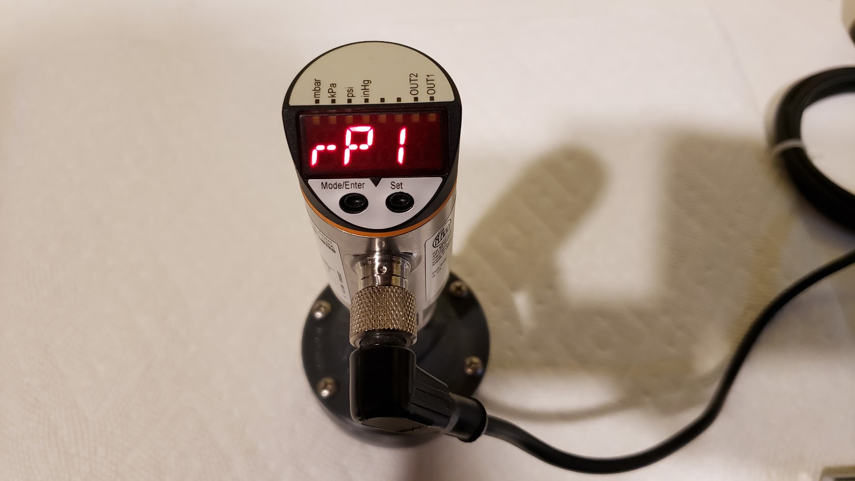
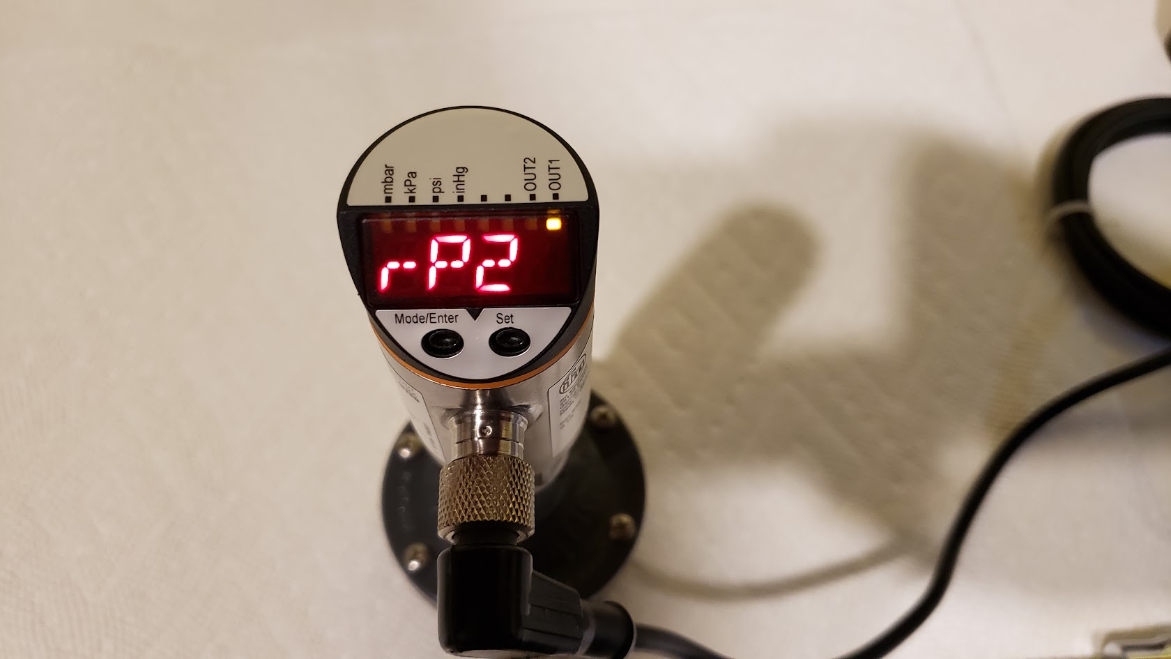
The programmable outputs on the IFM gives us the tools to setup an operation cycle for the CaRx. As the CO2 is dissolved, the pressure inside the reactor will drop. As it drops and hits the preset we have chosen for CO2 addition (rP1), the IFM will enable output1 allowing the addition of CO2. When the water level is below the float valve level, CO2 will be prevented from being added, so the lower preset of the feed pump output2 will trip (rP2), adding water into the reactor, raising the water level until the float valve closes and allows CO2 to be added. The newly added water raises the pressure inside the reactor as its being added, as the gas pocket is getting smaller, but it also dissolves CO2, lowering the pressure. The end of the cycle, is when the water level gets high enough to close the float valve, allowing the CO2 to be added, which trips the preset to halt the water addition (sP2), and the preset to disable CO2 addition (sP1). The cycle then repeats.
The hardware used in this build is sourced from the automation industry. This gives us the accuracy, reliability, and durability that we would never see if we were using components from the aquarium hobby. To do this in a budget friendly way, we are using some discontinued models, that are no longer available new, but are plentiful in the used and surplus markets. Because they were widely used in industry, equipment is constantly being broken down that contain them. So monitoring Ebay for a short period of time, typically presents lots of good candidates for them.
We are using a Clippard valve for CO2 metering, which is also used by the Carbon Doser, and is available new, directly from Clippard, and is not expensive.
The controller requires two continuous duty peristaltic pumps to operate. One for the effluent, and the other for the feed water. These cannot be dosing pumps as they will not handle the pressures involved or the continuous duty required. Either Masterflex or a couple models of Kamoer pumps are recommended. They must have an adjustable flow rate and keep their settings after a power cycle. The controller does offer the ability to interface directly to a Masterflex remote port for pump control.
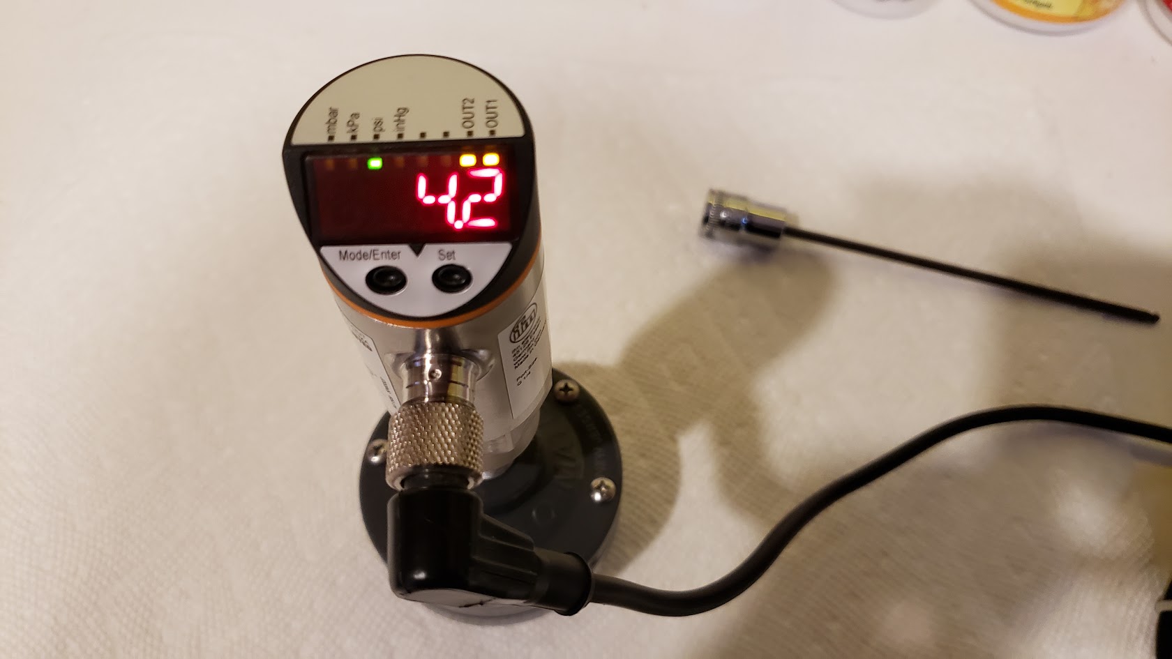
The IFM Pressure Sensor
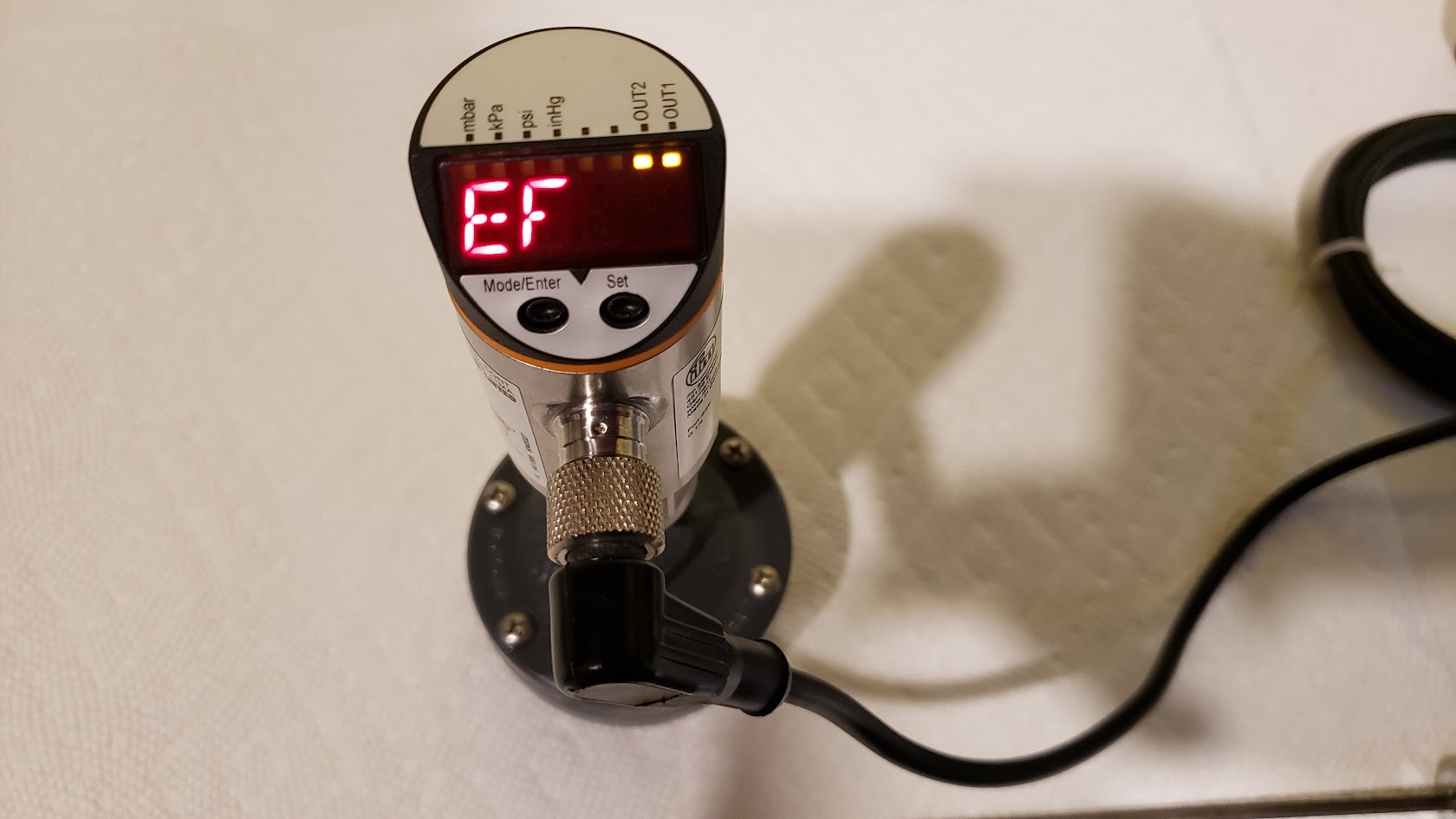
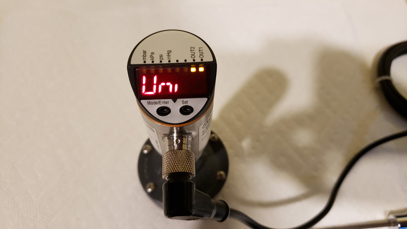
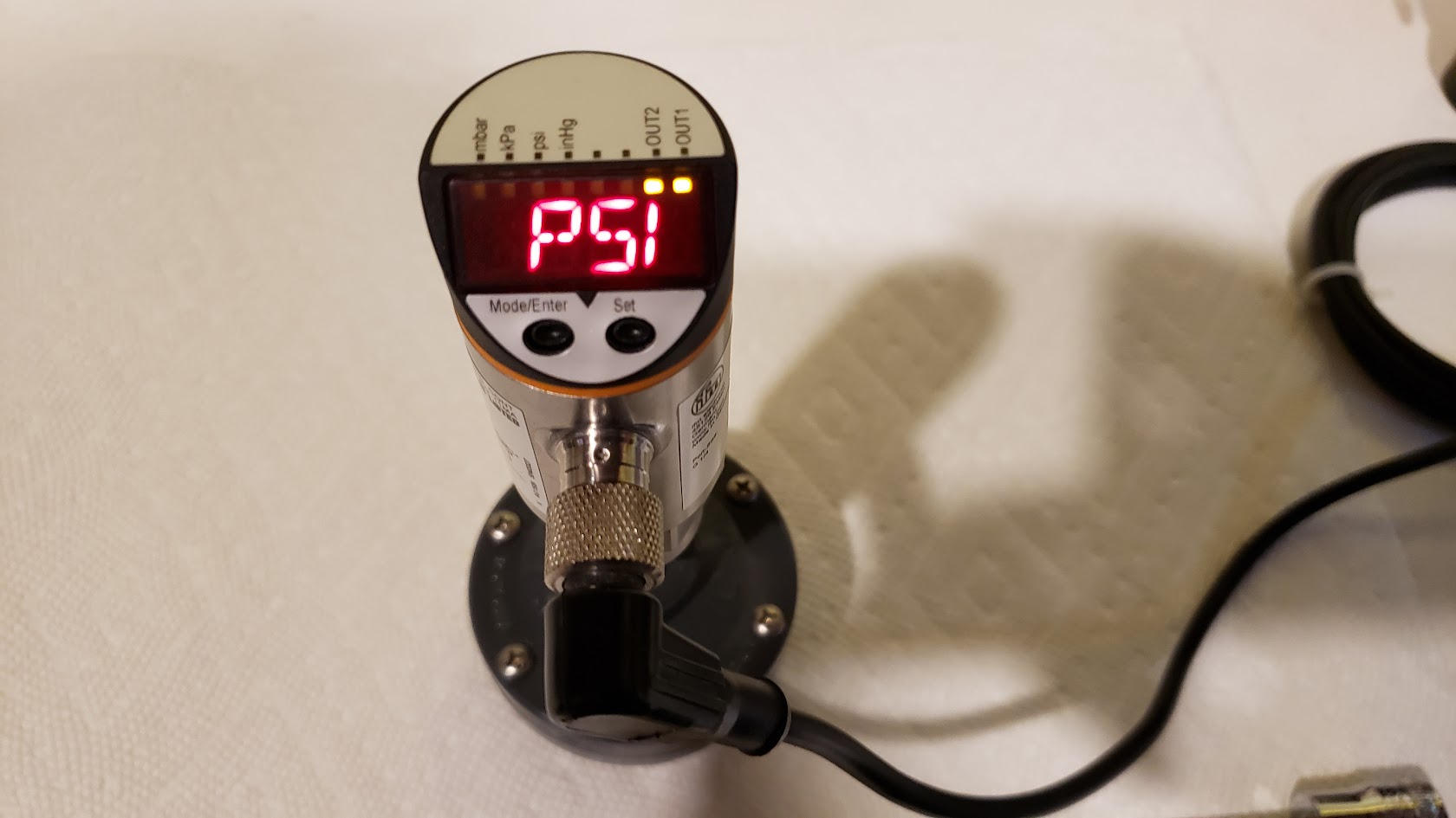
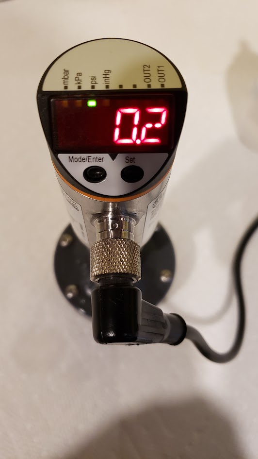
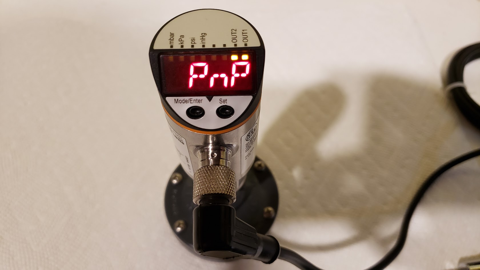
There area a couple of different models of IFM sensors that can be used in the v4 controller. The main requirements are that it must support 2 outputs, and offer a pressure adjustment in < 1 PSI increments. They are all programmed in the same manner and use the same configuration data. Configuring and making adjustments is quite simple, once you get the hang of it.
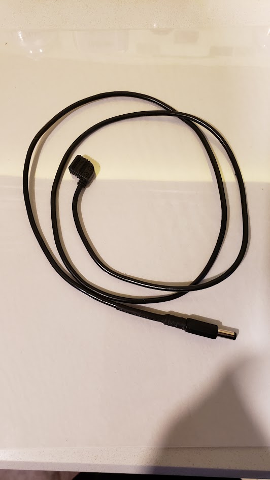
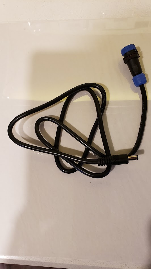
The 2 model numbers that work best for our controller are PN7007 and PN7207. They offer adjustments in 0.1 psi increments and and have a measuring range from 0 to 14.5 psi. The next best models are PN7006 and PN7206. They offer adjustments in 0.2 psi increments and and have a measuring range from 0 to 36.3 psi. The last models that will work are PN7009 and PN7209. They offer adjustments in 0.2 psi increments and and have a measuring range from -14.5 to 14.5 psi. Other models of IFM sensor may work, but are not recommended, as they will likely impact the operation of the controller. The sensors use an off the shelf cable, that is inexpensive, and is available online (Automation Direct).
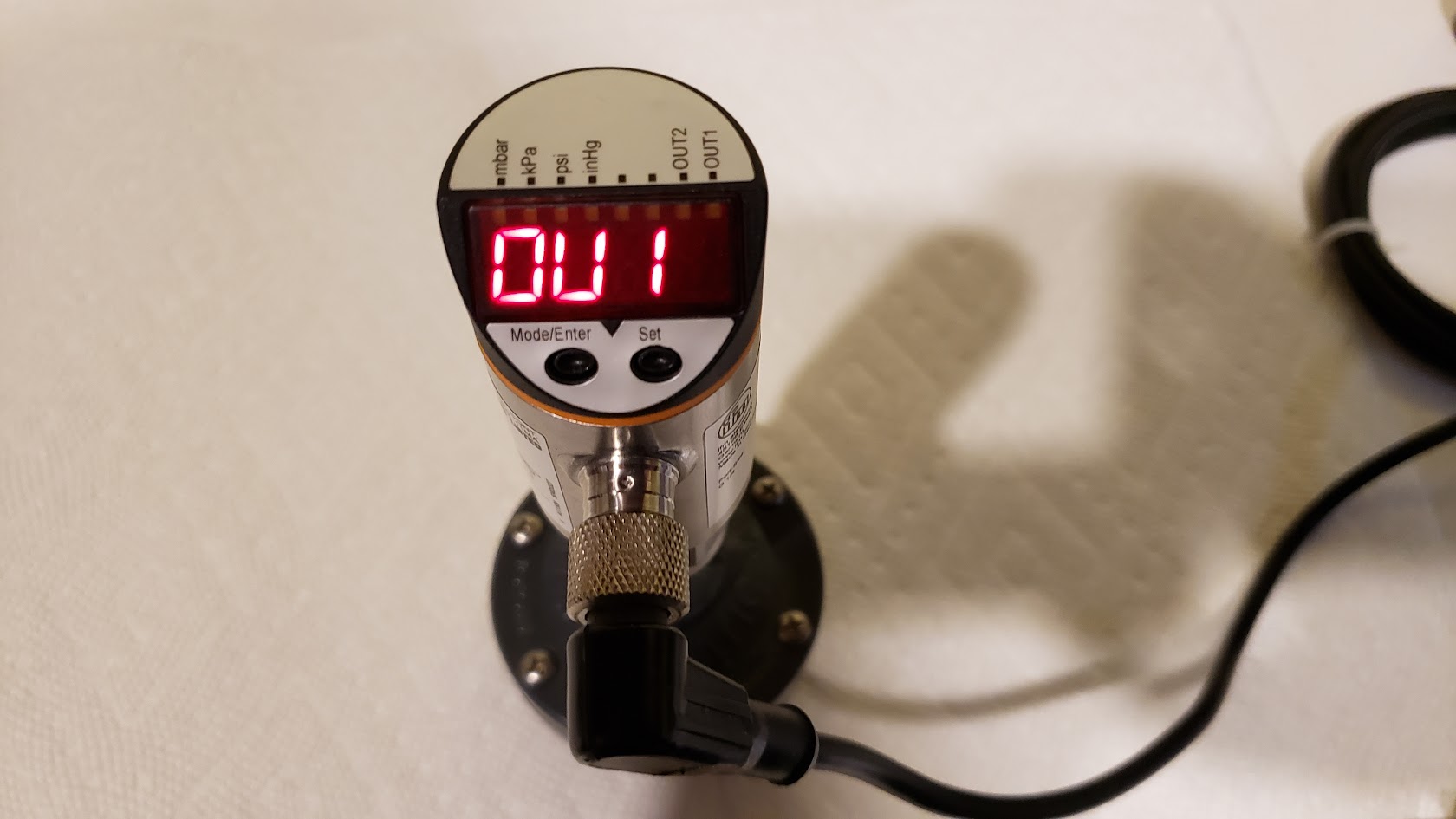
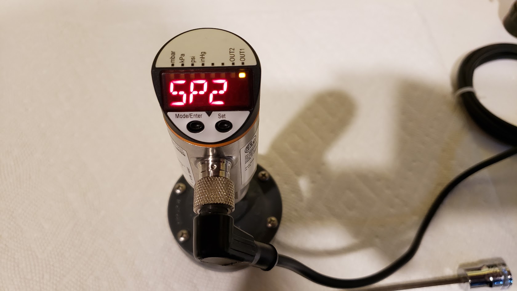
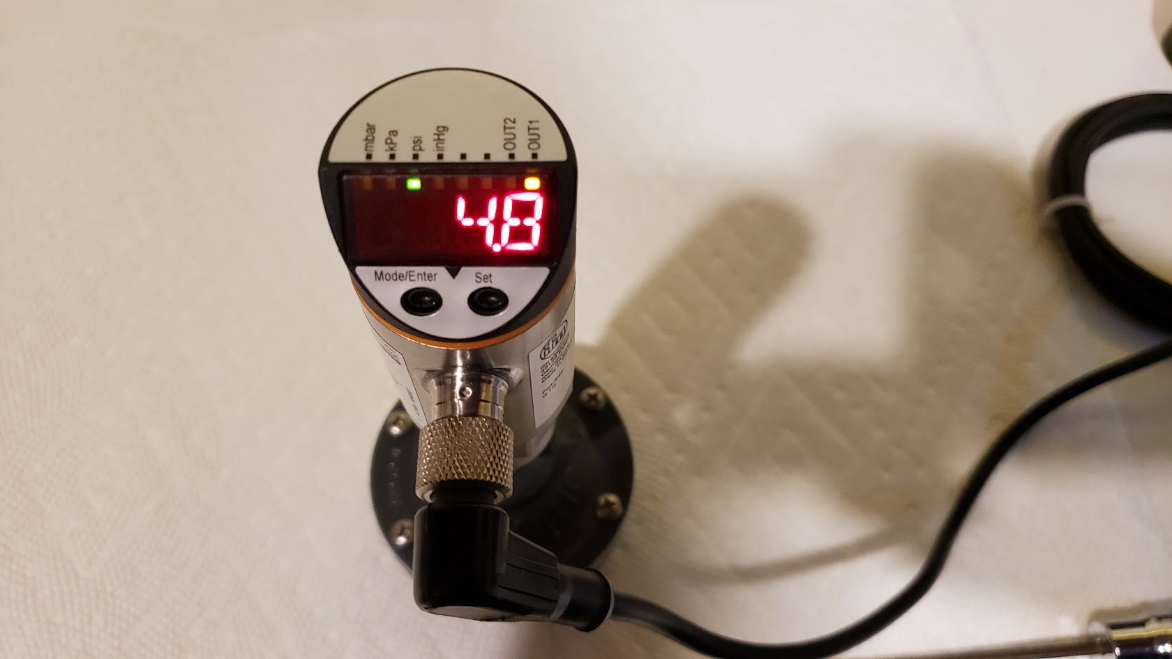
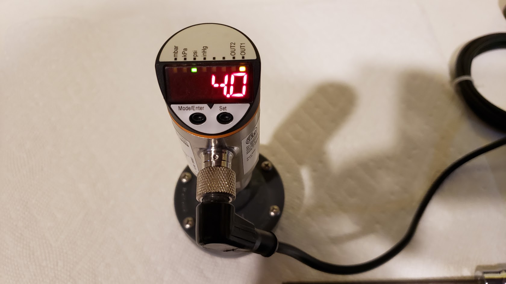
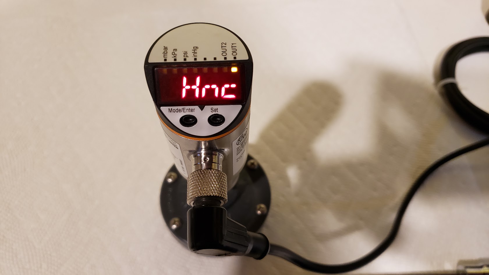
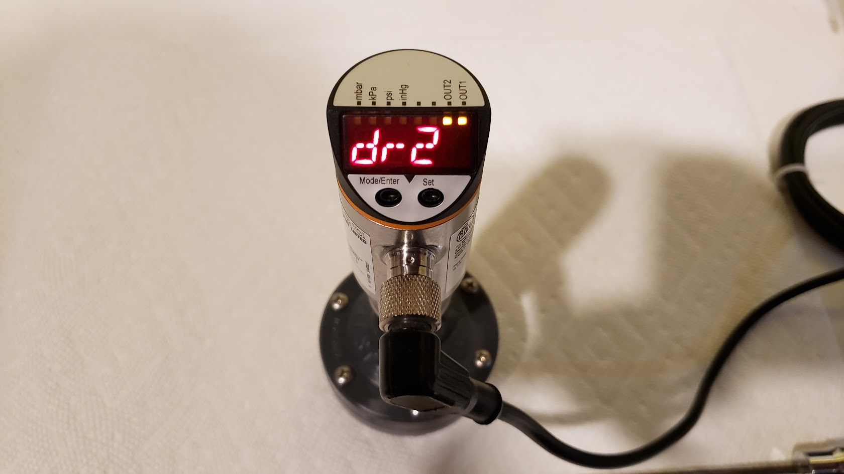
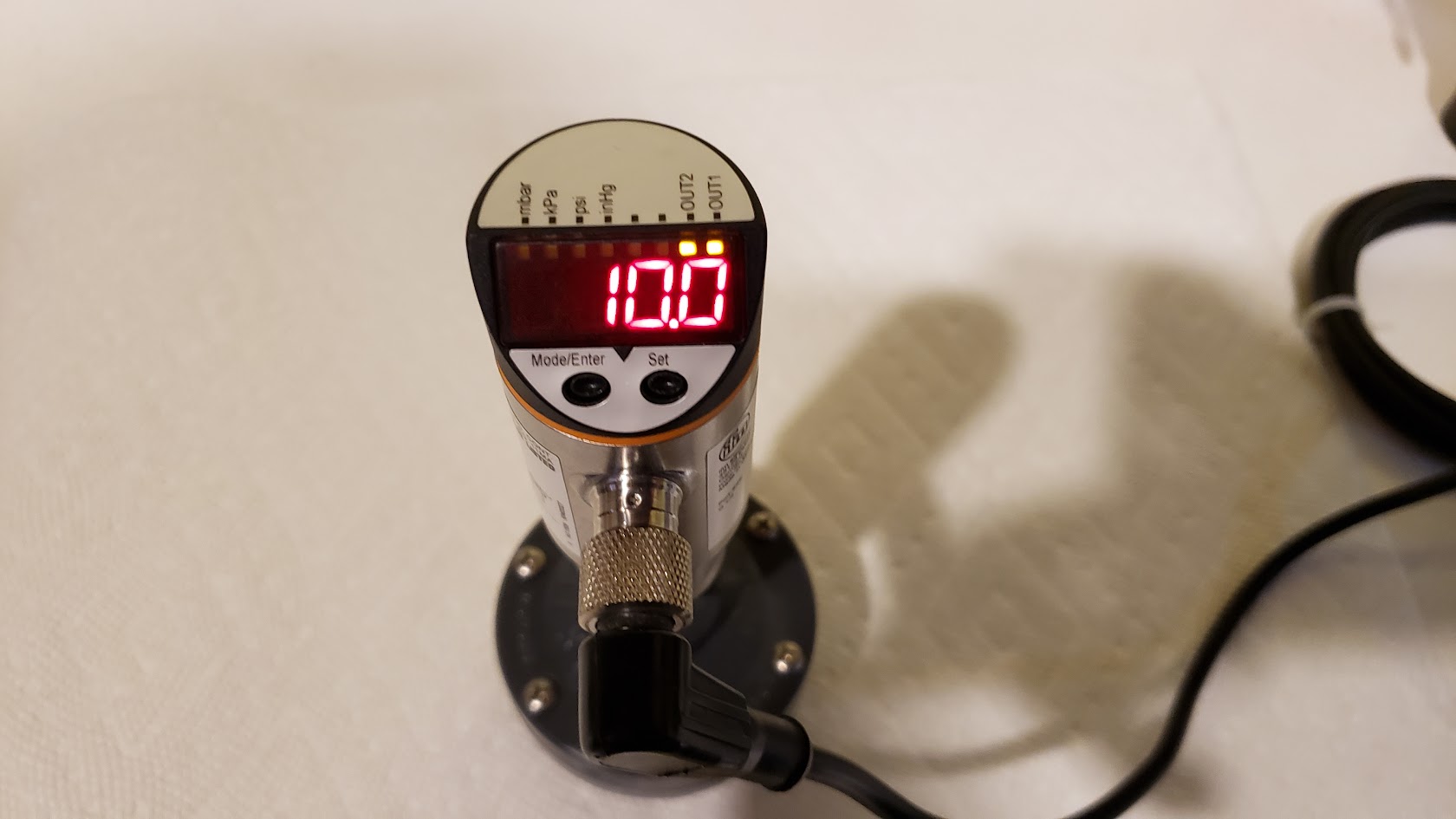
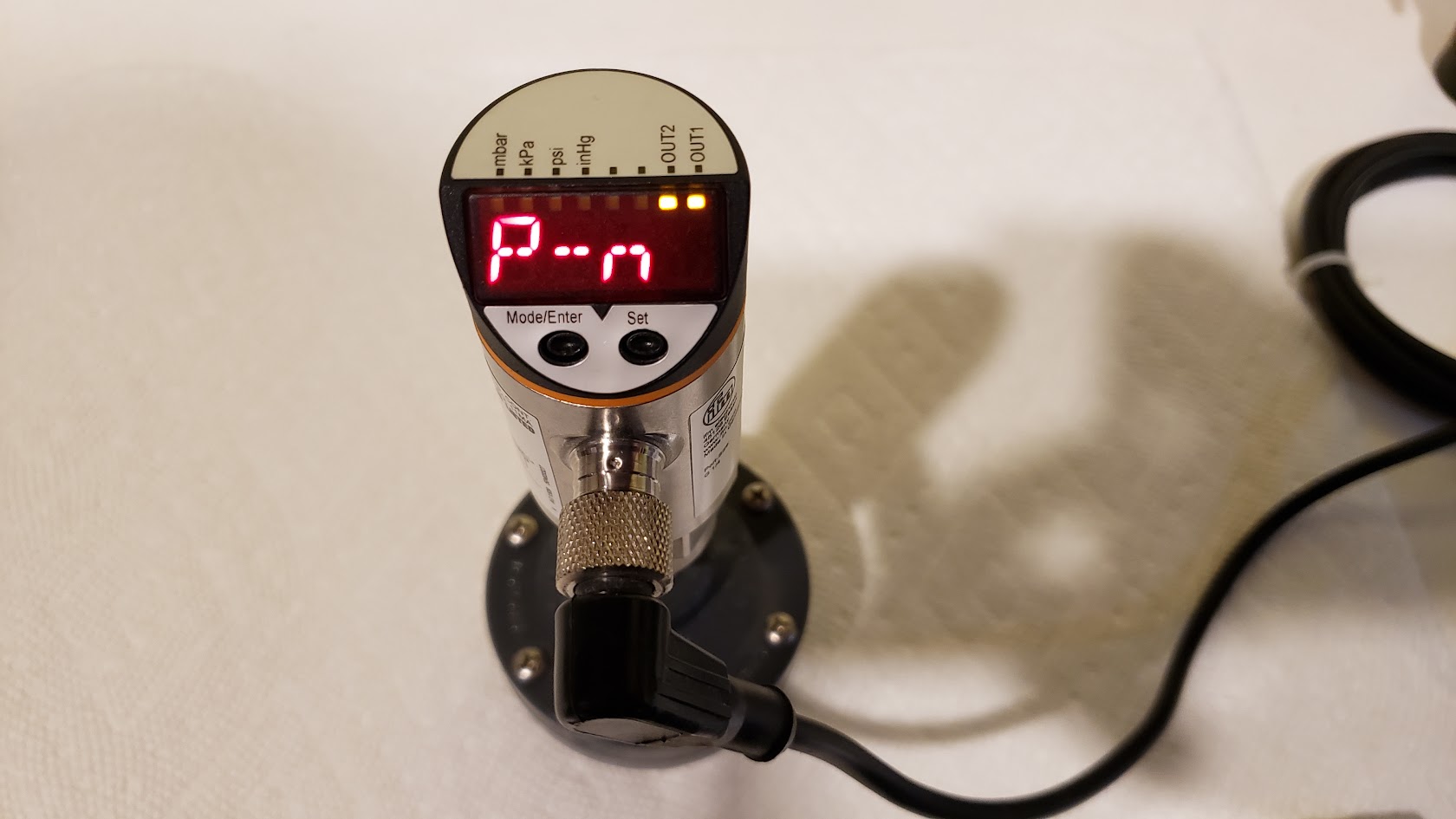
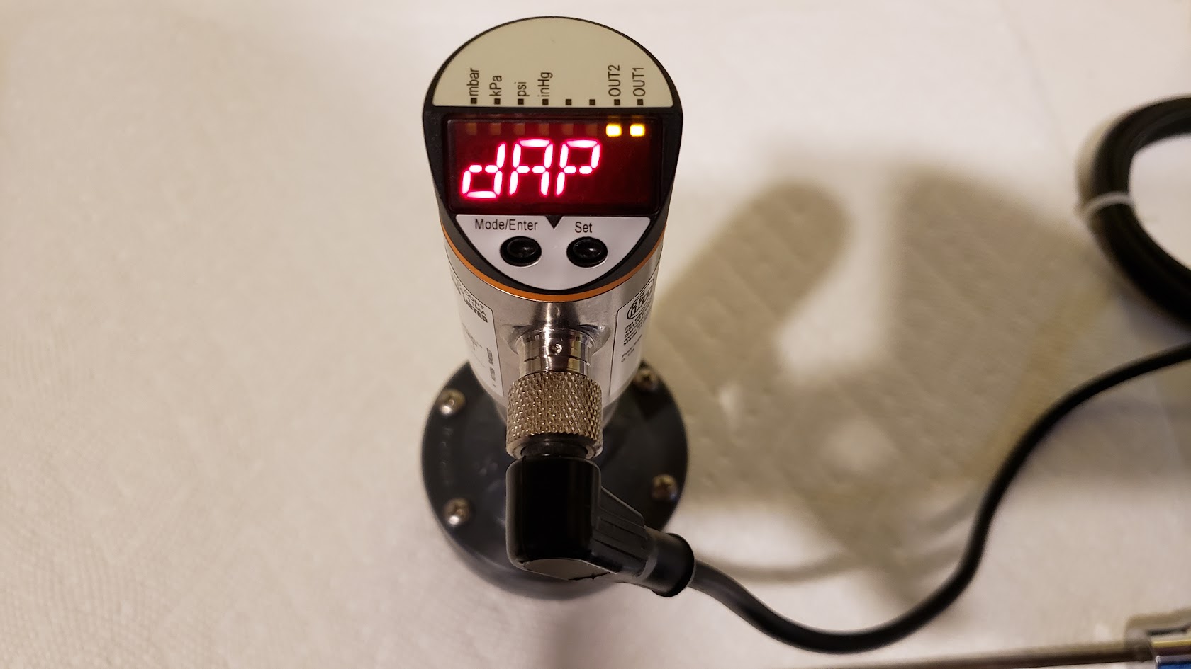
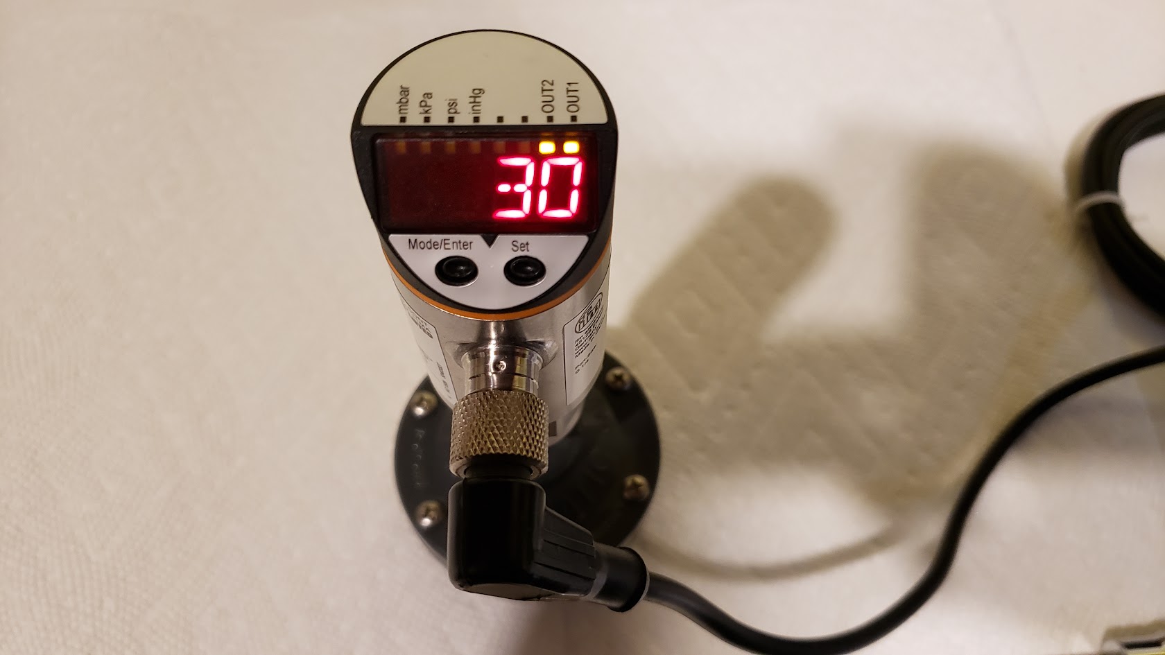
Programming the IFM sensor requires stepping through a menu structure using a push button, and then adjusting specific settings using a second button. For proper operation of the controller, the settings must adhere to the following:
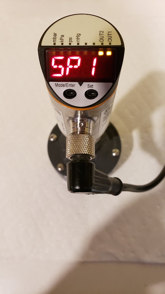
sP1 > sP2 > rP1 > rP2
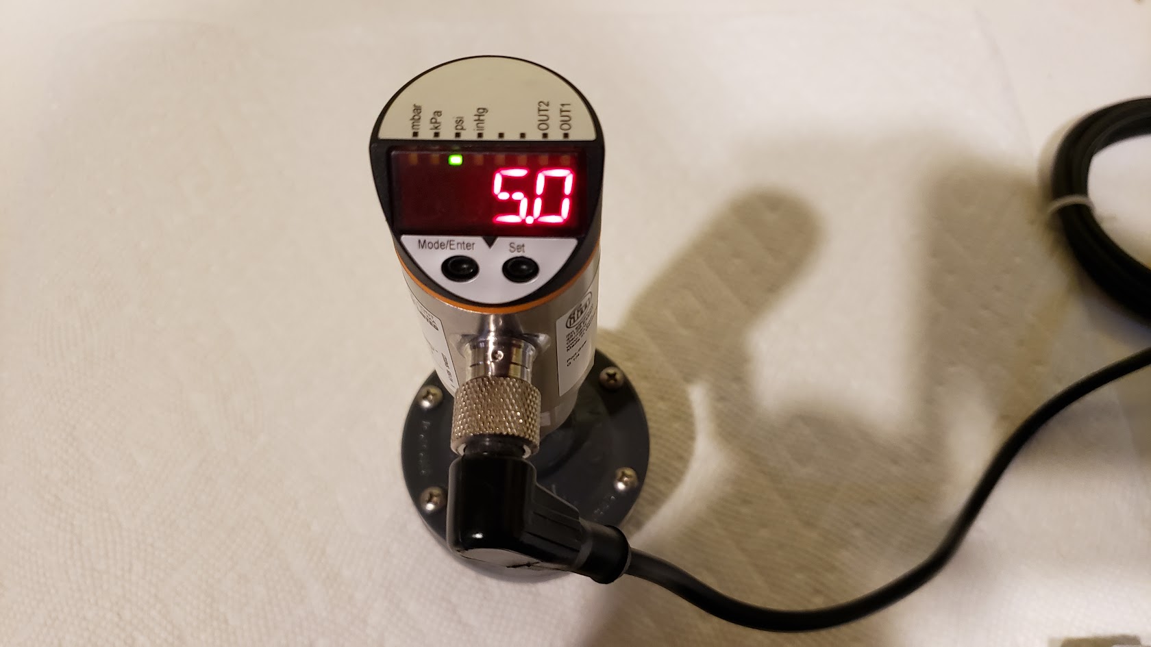
Example Configuration: sP1=5.0, sP2=4.8, rP1=4.2, rP2=4.0
sP = Set Point
rP = Reset Point
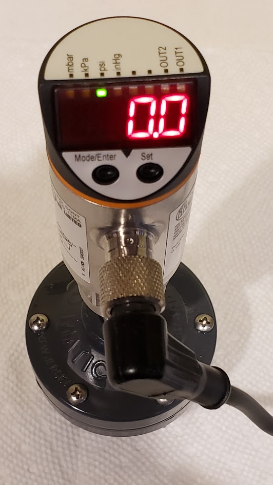
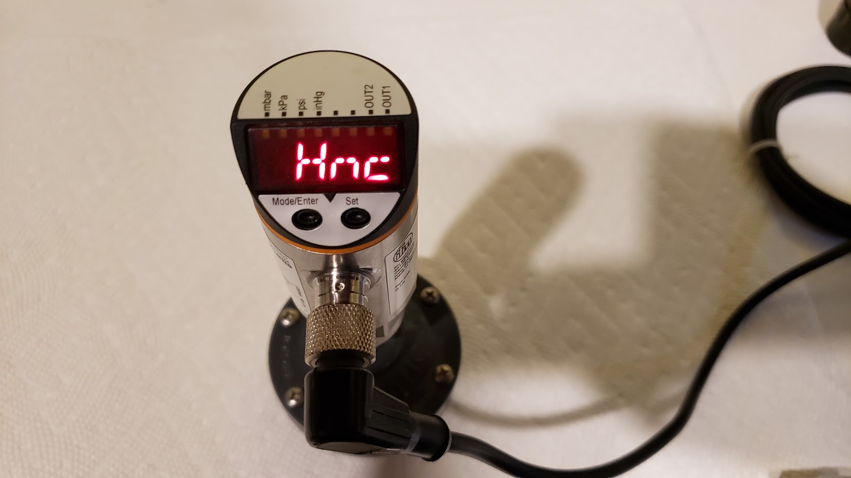
The IFM outputs are configured for hysteresis, normally closed (Hnc). They are energized until the psi reaches the set point, then are de-energized, until the psi drops to the reset point.
Note, the following is not necessary to know or understand to use or configure the controller, and is provided for those that want to understand the relationship between pressure and volume changes during reactor operation
The differential between rP2 - sP2 is important and must be large enough to allow enough time for the feed pump to overcome the effluent pumps flow rate and raise the water level far enough to trigger the float valve. A difference of 0.6 - 0.8 psi is sufficient for the pressure range 4.0 - 5.0 psi. As the target pressures are increased, the difference required shrinks. This is the effect of Boyle's Law. So we can easily calculate how much volume change a given pressure difference will provide with the formula P1V1 = P2V2. For example, with the pressure settings of 4.8 and 4.0 psi and a volume of 100 at 4.8 psi, the volume at 4.0 would be 120, an increase of 20% (4.8 / 4.0 * 100 = 120). As the pressures involved rise, the percentage of volume change required decreases.
This also highlights why the IFM models that only offer 1 psi adjustments are not suitable. Using 6.0 and 4.0 psi (sP1=7.0,sP2=6.0,rP1=5.0,rP2=4.0) we would get 6 / 4 * 100 = 150, needing a 50% change in volume to hit the lower preset. We would have to operate at double the pressure, 10 psi, to achieve the same volume of change that the smaller pressure range required (sP1=5.0,sP2=4.8,rP1=4.2,rP2=4.0). The percentage of volume change required to advance the cycle is affected by this, and will affect the reactor's ability to keep up with high demand tanks. Using the IFM sensors that offer the smaller adjustment range limits keeps the required volume changes reasonable and improves cycle response.
In practice, that is not quite the whole story though, as the pressure of the gas pocket will be constantly decreasing as CO2 is dissolved into the water column, without changing the volume of the pocket. The ratio of the pressure change attributable to CO2 being dissolved will be impacted by how fully saturated the water column is at that point.
Other Hardware
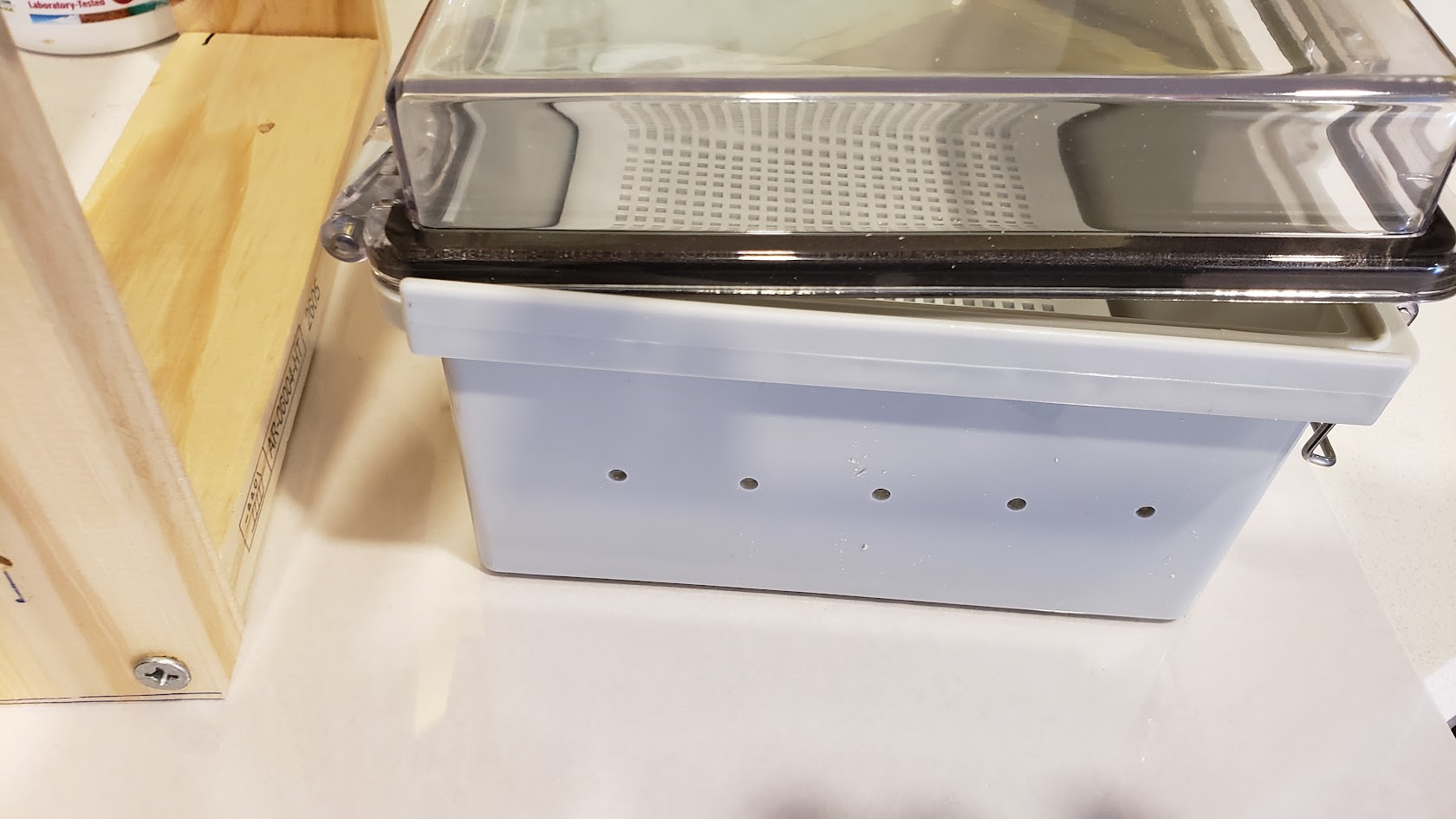
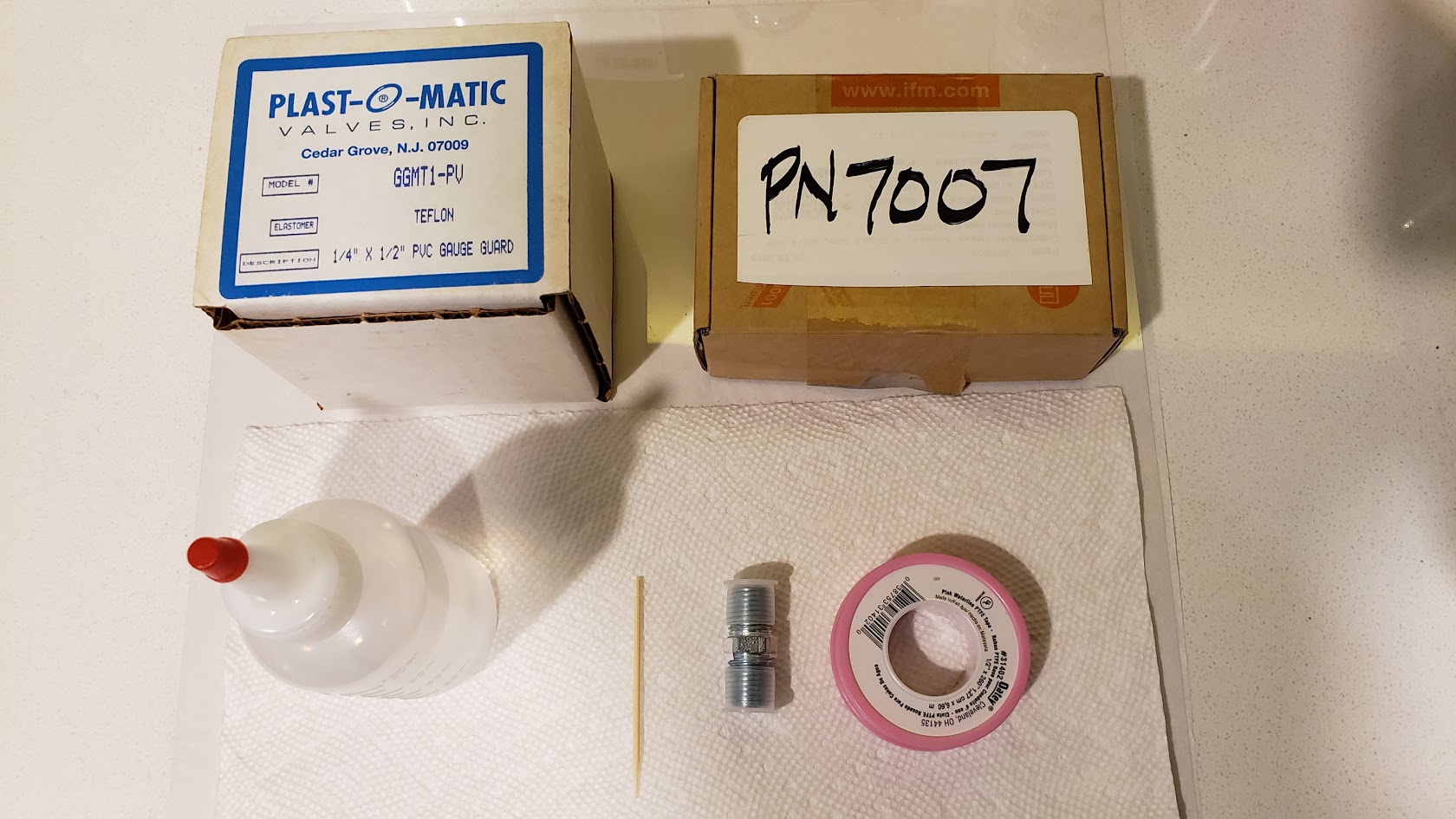
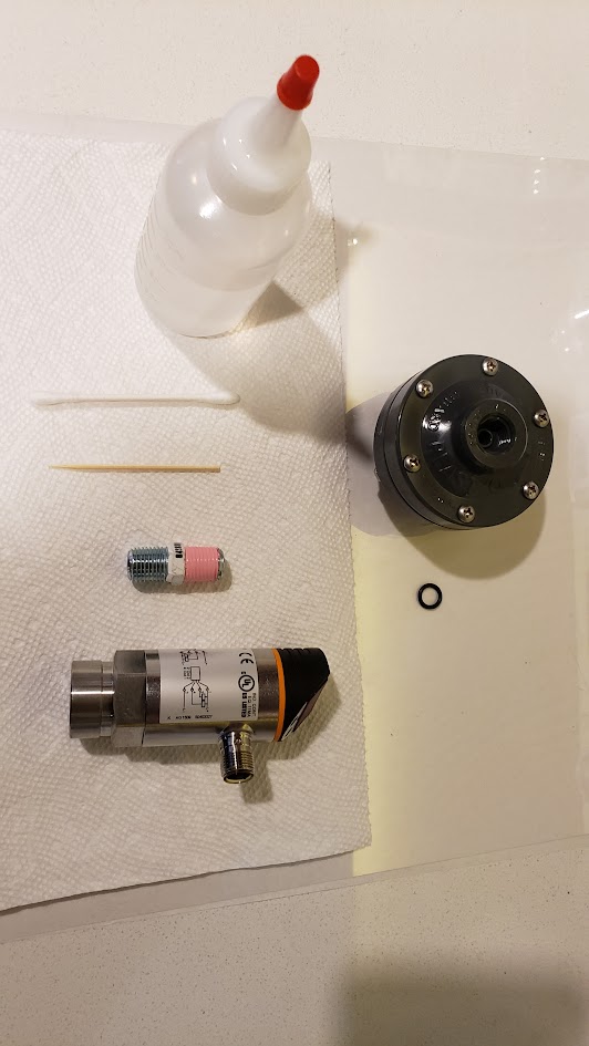
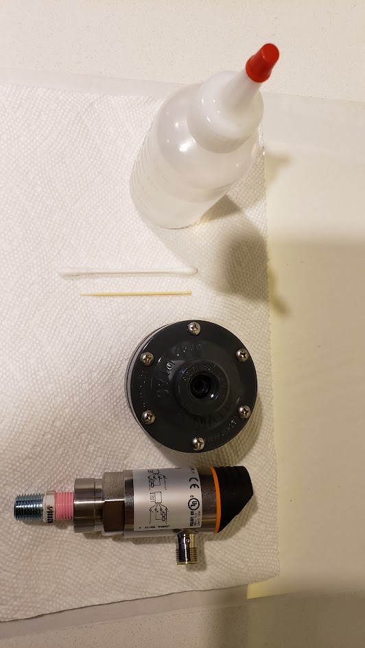
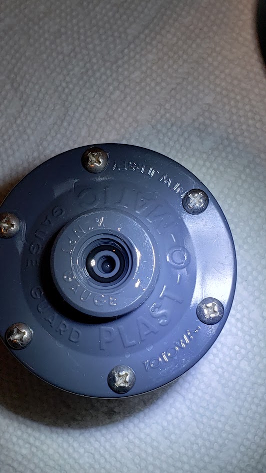
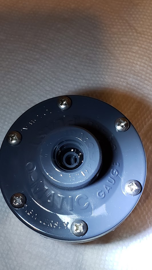
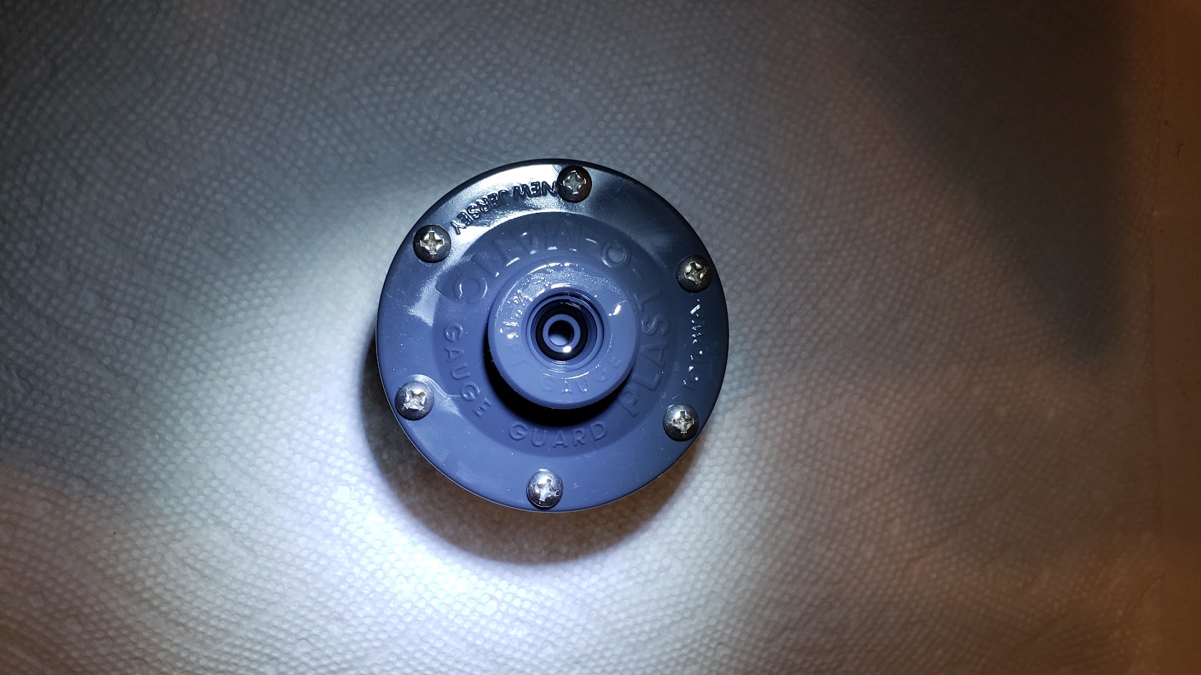
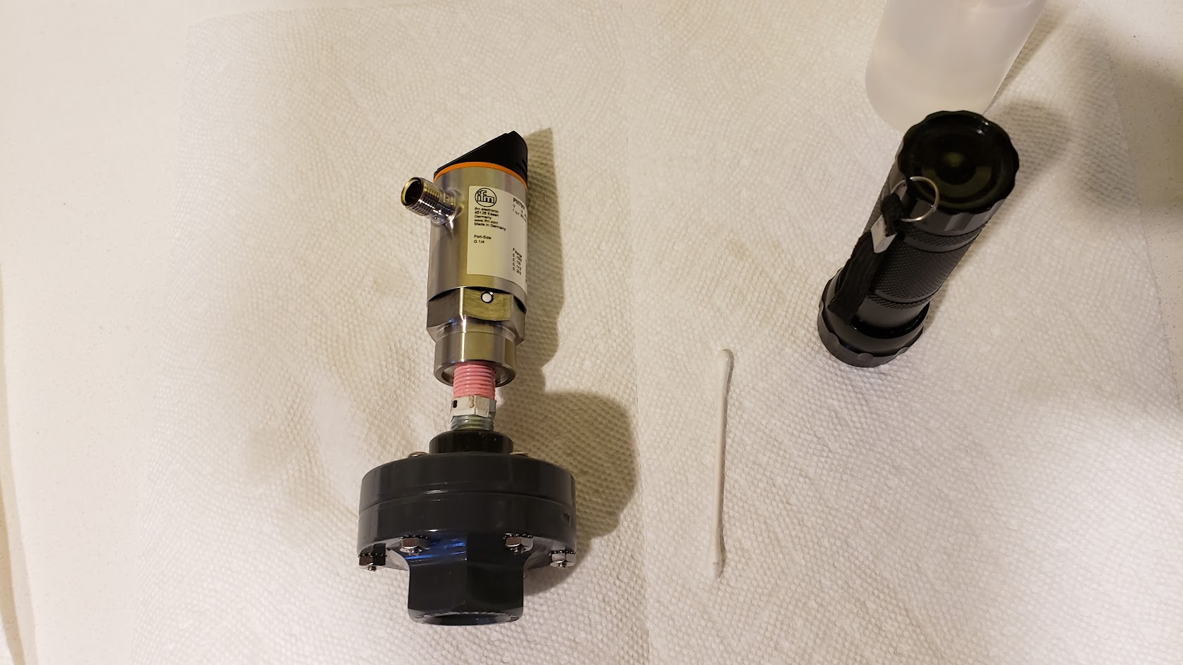
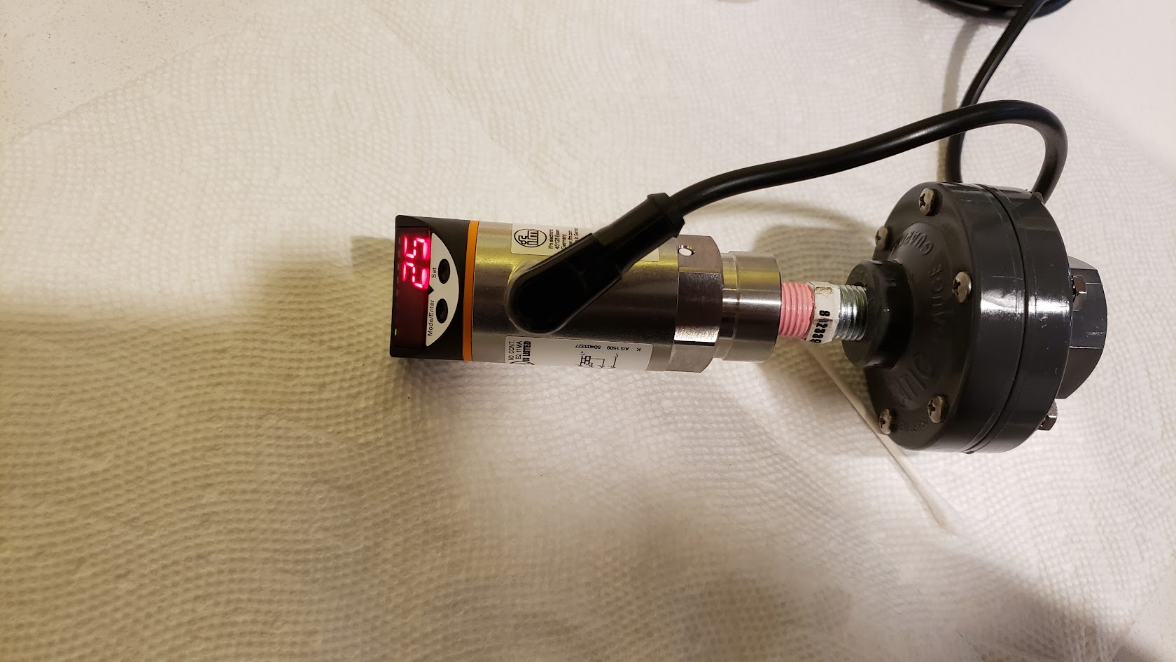
The IFM pressure sensor has to be installed after the check valve in the v4 design. So a protective membrane is required to allow the sensor to sense the pressure, without coming into contact with the saltwater. These are commonly called a gauge guard. For this we use the Plast-o-matic GGMT1-PV. This is a discontinued part, but is commonly found on Ebay, usually as NIB (New In Box), off the shelf surplus. Where possible, it is best to get a NIB part for this to give peace of mind that nothing harmful has come into contact with the membrane that will be exposed to the reactor water.
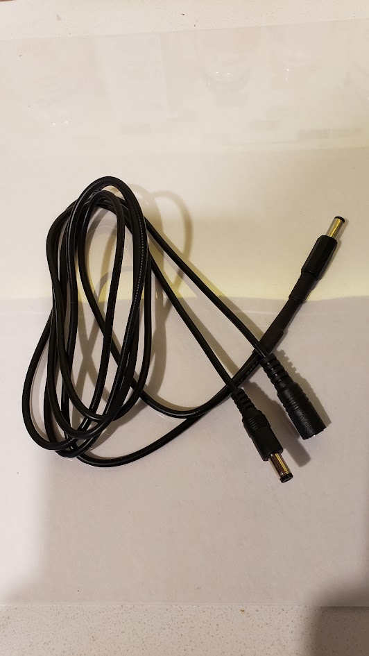
The CO2 is metered by a Clippard EV Mouse valve (ET-2-24). This can be purchased new, along with a connection cable (ET-C48) directly from Clippard or one of their distributors.
The reactor will need to be vented to exchange the accumulated gas, for fresh, pure CO2. Depending on flow rate, this will be required from weekly to daily. To automate the process, a 3-way isolation valve is required. The best candidate for this is the Neptune Research 648T032 . This valve operates at 24VDC, has 1/8" NPT ports, and a large enough orifice (3.0 mm). Again Ebay will be required to find one. They are not as common as the IFM and Plast-o-matic parts, so some patience may be required. The even less common 648K032 and T648K032 parts will also work. It is unlikely that you will find these as NIB parts, so be sure to inspect the PTFE valve surfaces for any residues and give the valve surfaces a rinse with RODI just to be safe.
When purchasing the IFM, Plast-o-matic and Neptune Research parts, I consider $50 each to be a good price, and anything under $50, is a good deal. For the Neptune Research valve, you may have to go higher, say up to $100, to secure one.
Venting the CaRx
Periodic venting of used CO2 is required to maintain consistent effluent strength. How often you vent, depends on the flow rate through the reactor. The higher the flow rate, the more frequent venting is required.
The controller supports both manual and automatic venting. For manual venting, a manual 3-way valve is inserted into the CO2 re-circulation line, between the cap and the venturi valve. The valve and the vent switch in the controller allow the controller to be put into vent mode.
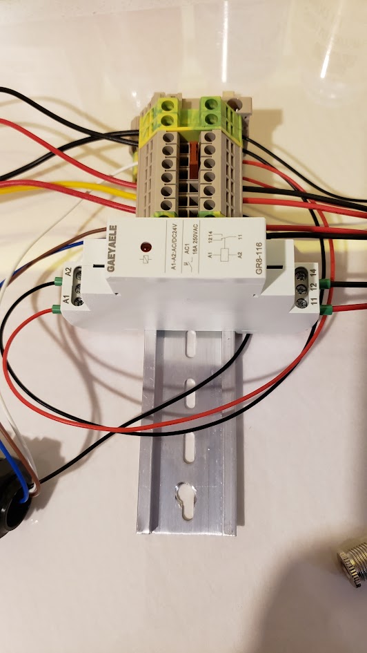
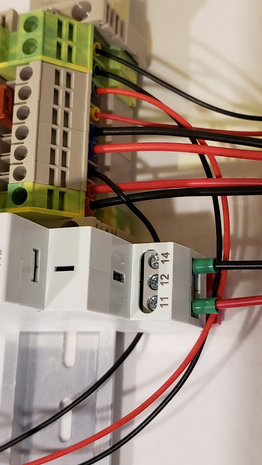
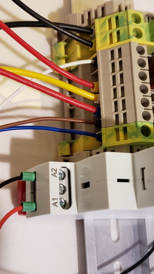
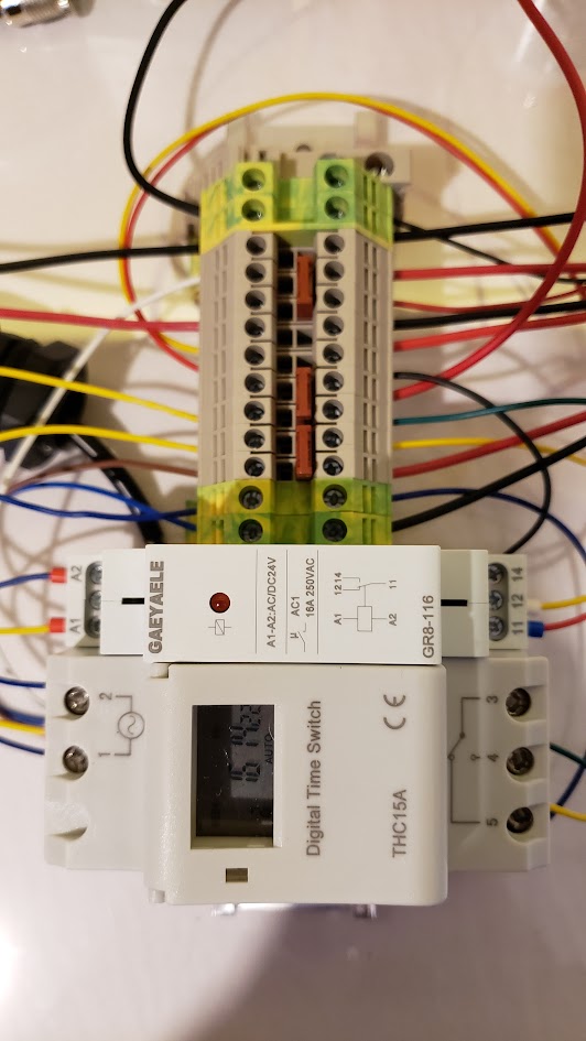
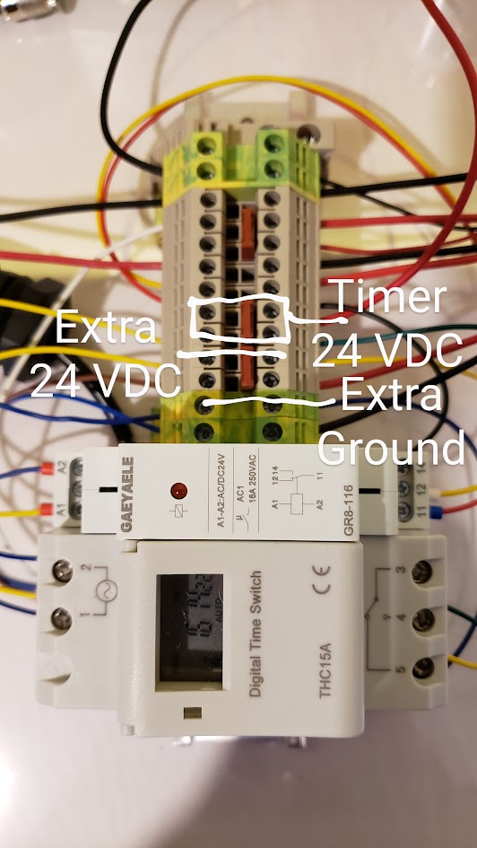
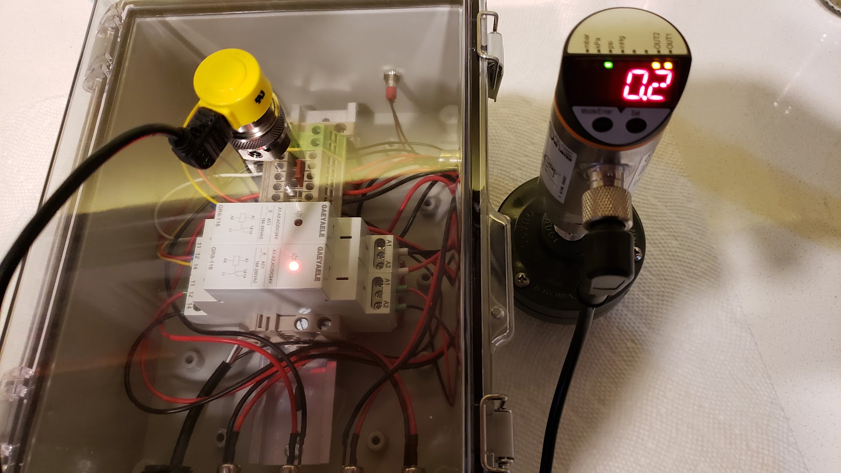
For automatic venting, the vent switch is replaced with a relay, and an electronic 3-way is installed in the CO2 re-circulation line. A timer can be used to energize the relay and 3-way to allow the venting process to proceed. This can also be driven externally from an Apex or other tank controller by energizing the 3-way and providing 24 VDC into the vent port of the controller to energize the relay.
The venting process is also used for reactor startup to force all air from the system. Once the venting line is expelling water, discontinue venting and the controller will establish the CO2 pocket.
The v4 Circuit Diagram
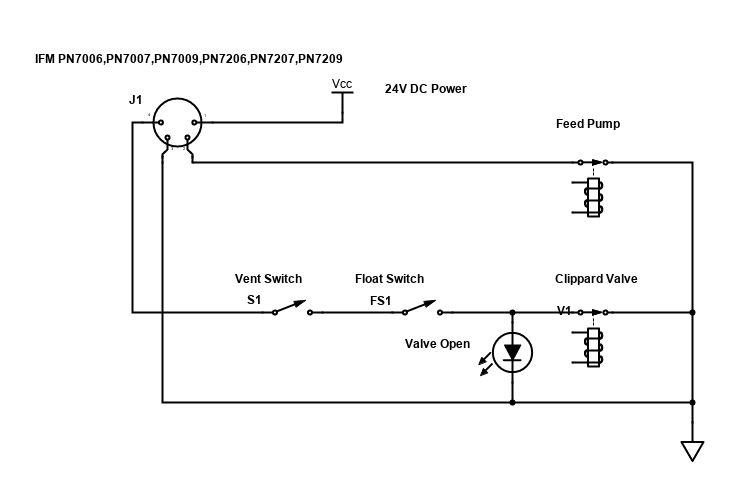
ACR Controller v4 PDF
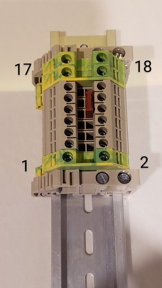
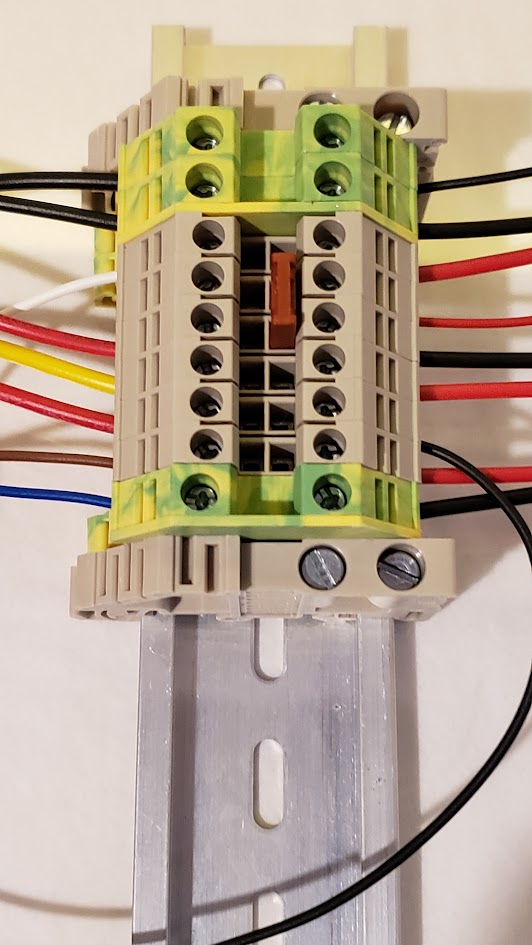
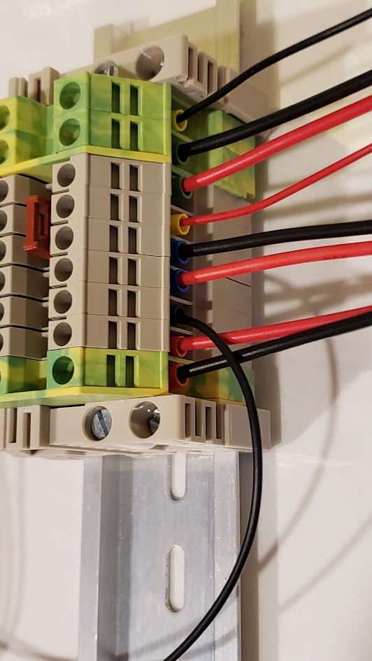
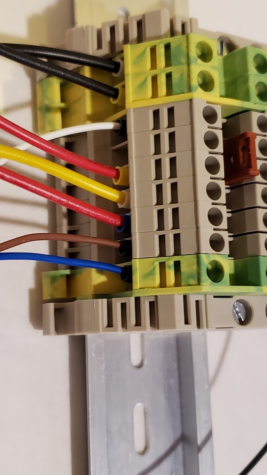
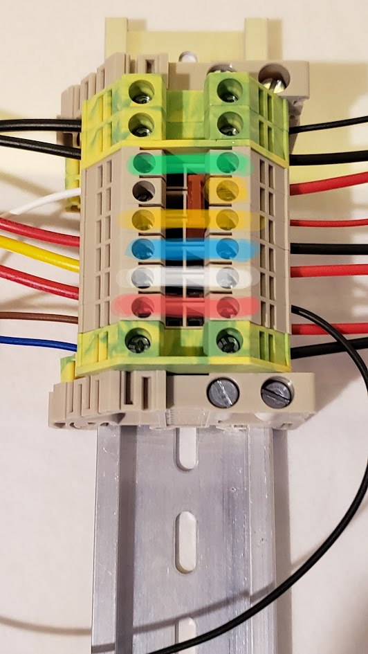
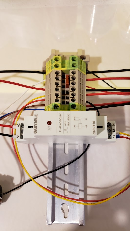
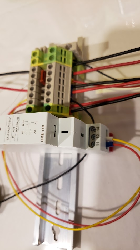
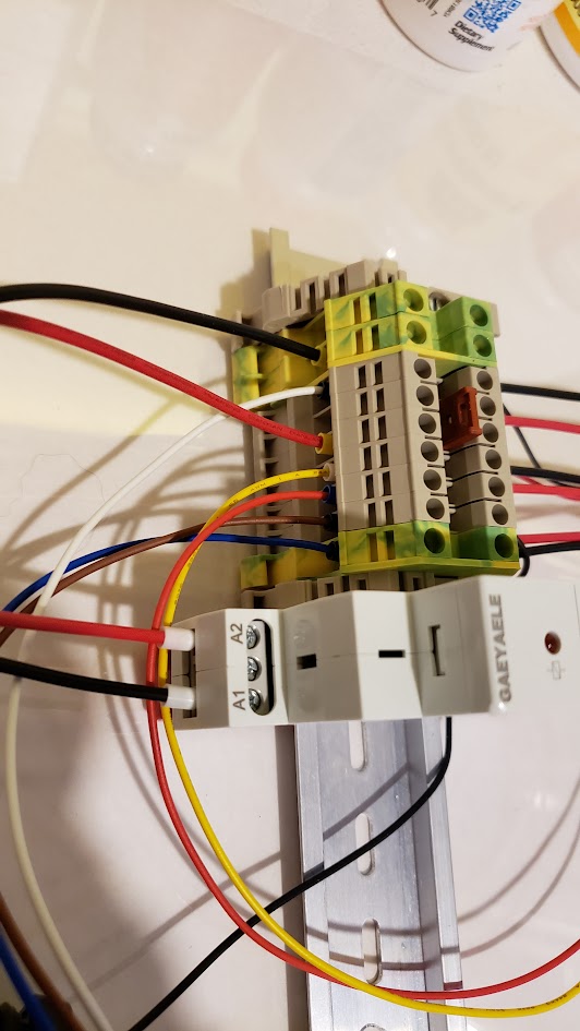
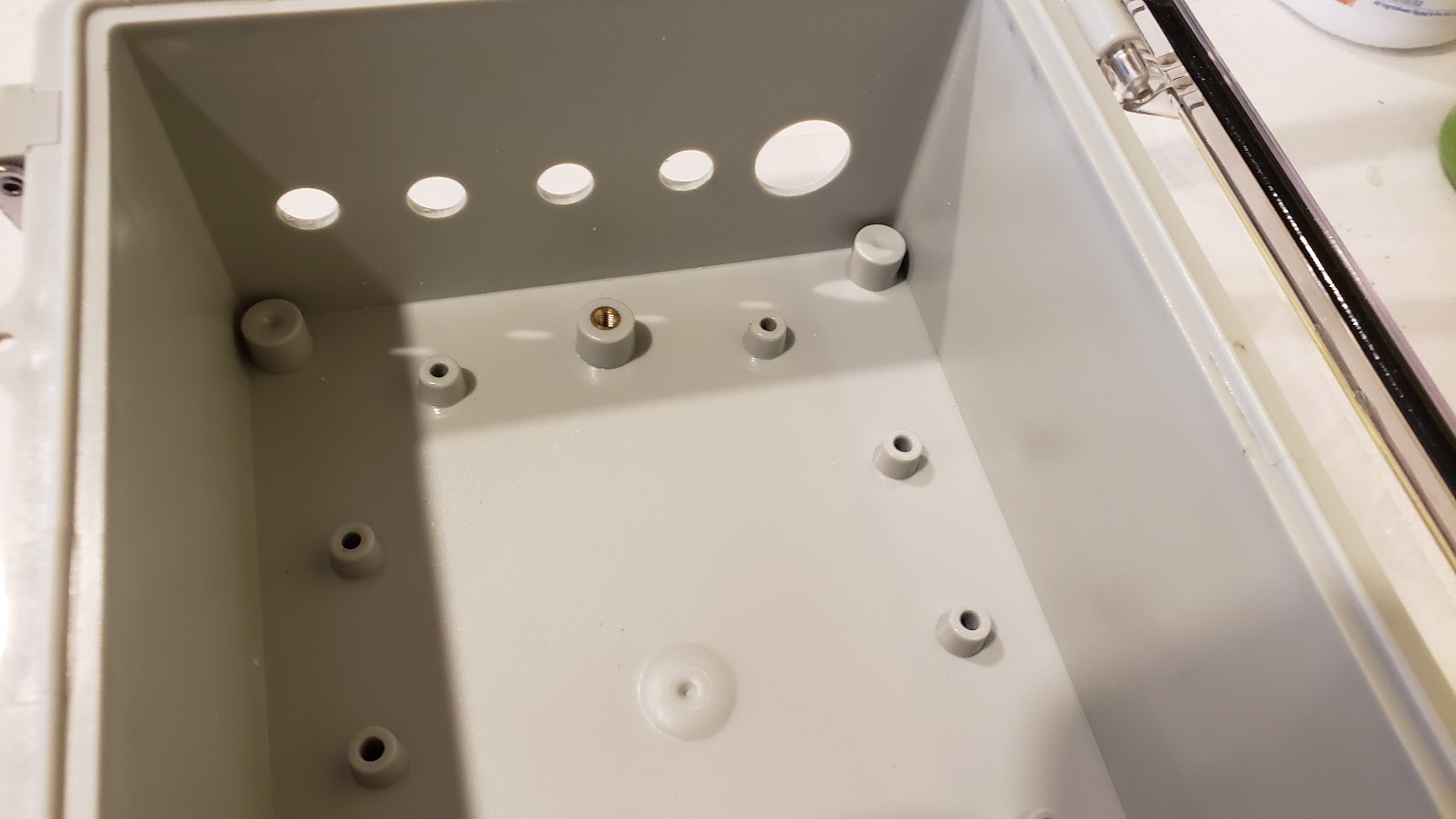
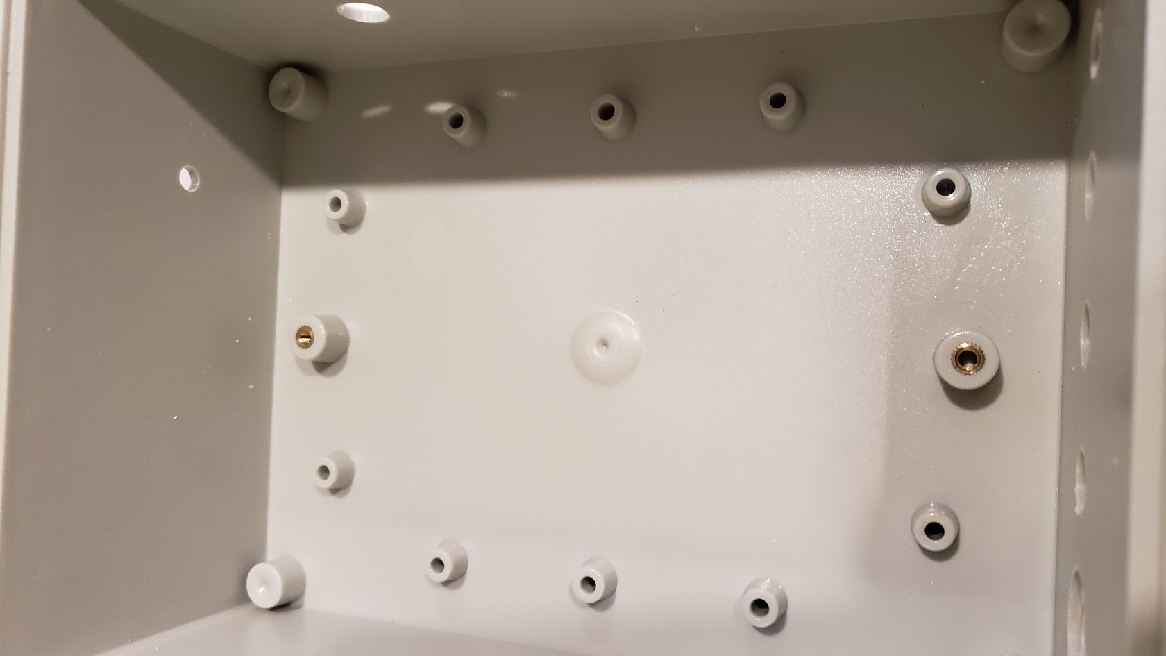
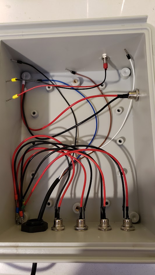
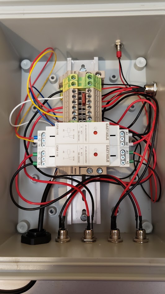
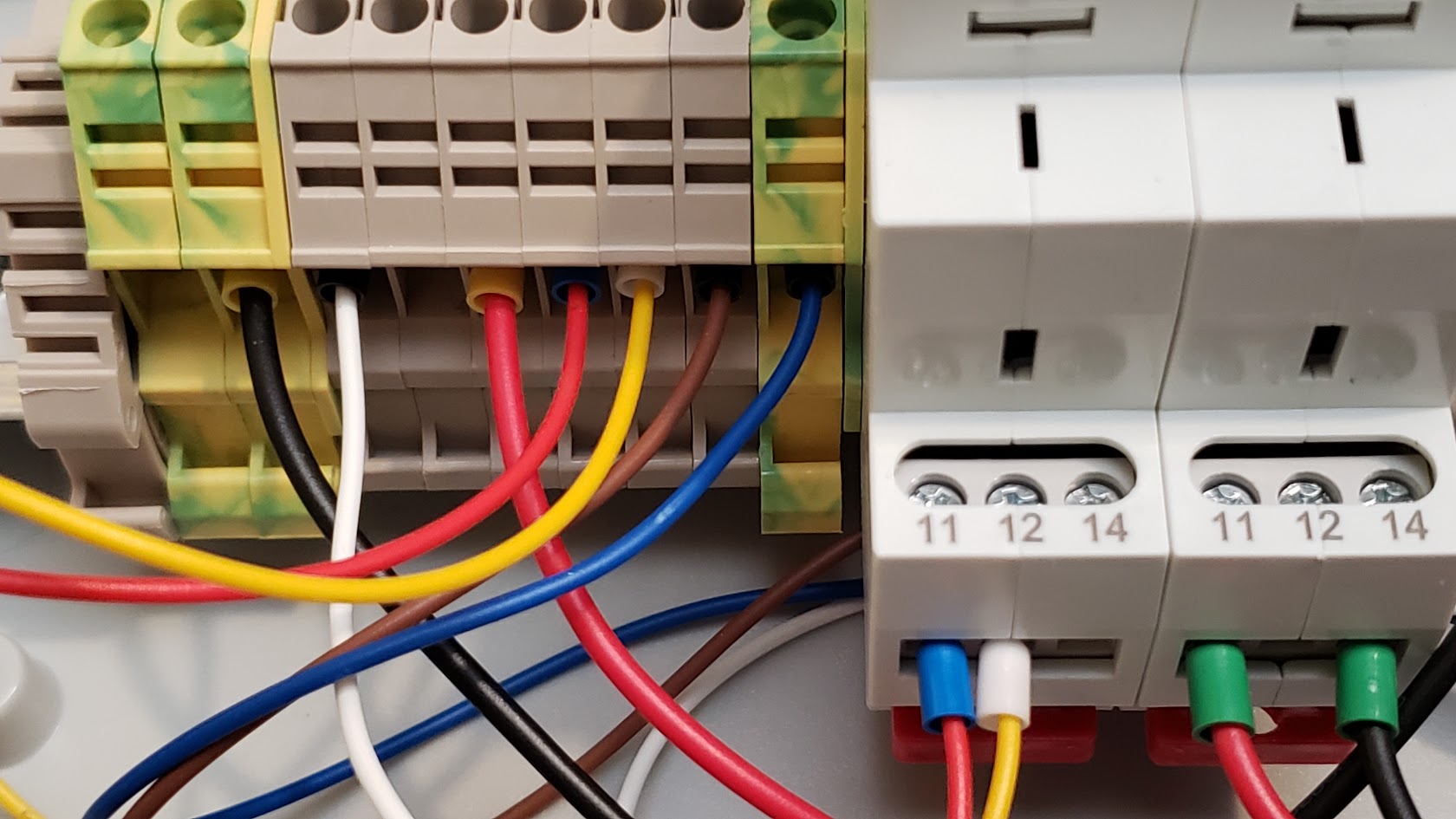
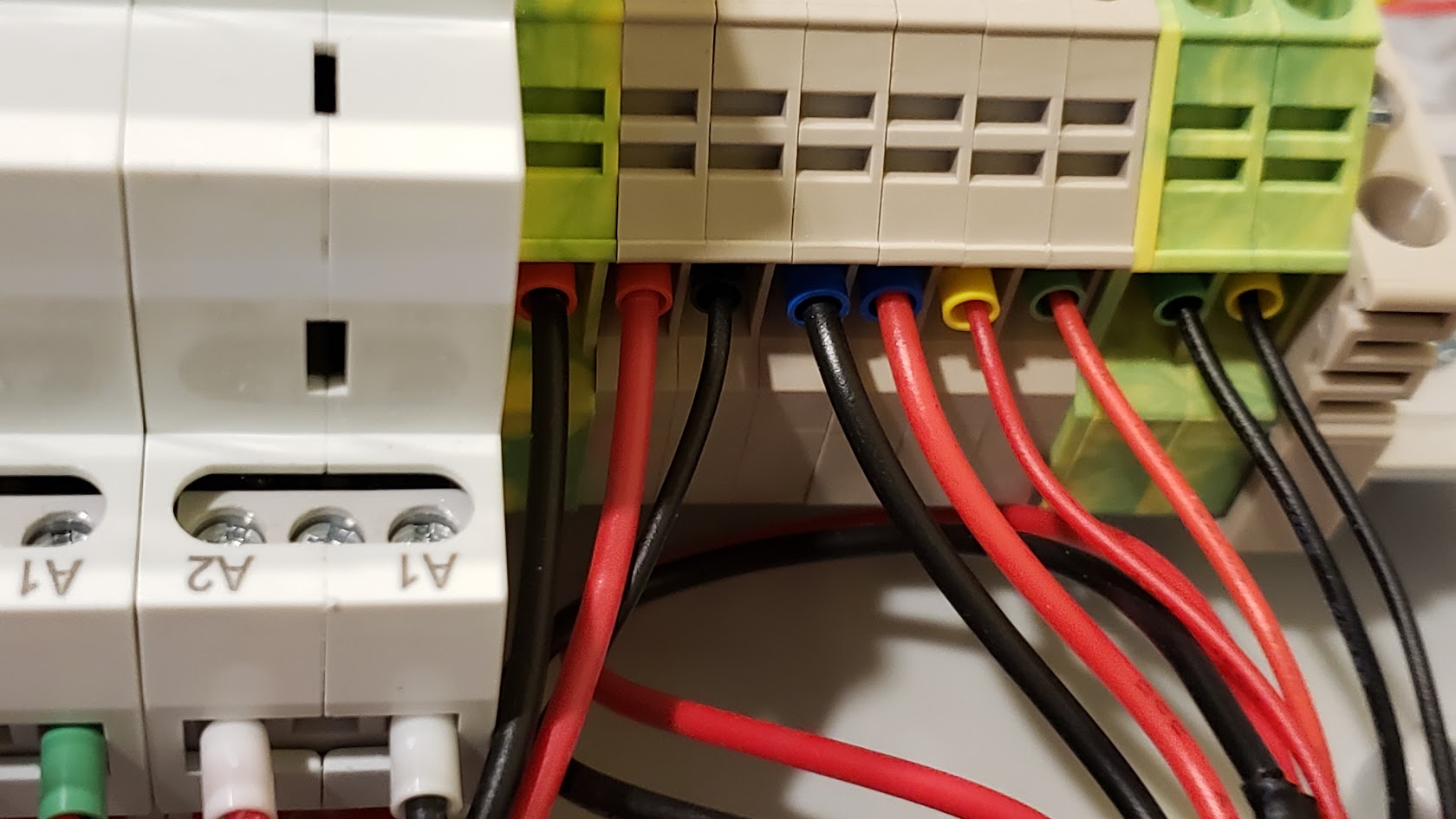
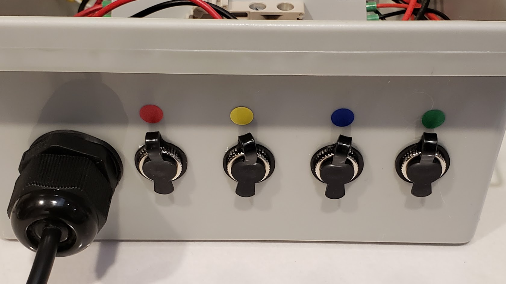
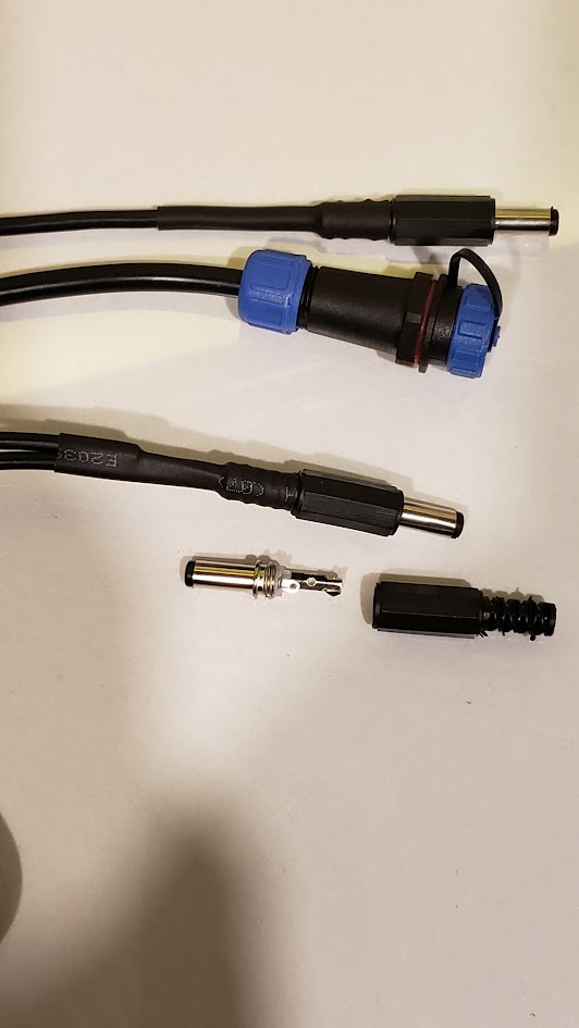
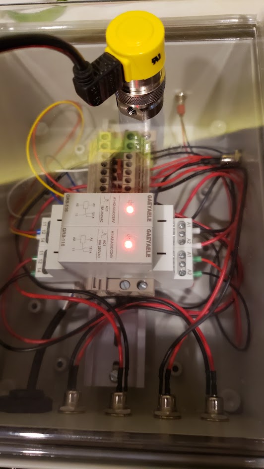
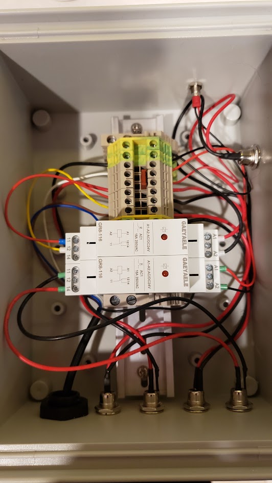
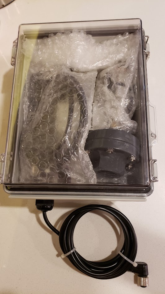
Photos of the example build be posted as they become available.
History
The AE ACR is a line of CaRx that use a float switch to regulate the addition of CO2 in a similar way to the Dastaco and Deltec units. This allows them to operate in saturation mode, dissolving CO2 into the water column until the saturation point is achieved, and no more CO2 will dissolve. This eliminates the need for a pH probe and bubble counter and makes them automatic. The only adjustment required of the user is how much flow through the CaRx to set the supplementation level.
AE recently ceased operations and the ACR units have been orphaned. As well the factory controllers have an abysmal track record of failing after about a year of operation. When I experienced this firsthand, I decided to design a replacement controller that addressed the shortcomings of the factory version.
The v1 design just used a Clippard EV Mouse valve inline with the float switch. This is the same valve used in the Carbon Doser and in my CO2 Tank Auto Switcher.
The v2 design added an IFM pressure sensor to provide feedback on the pressure the CaRx was running at. I found the pressure sensors by chance while searching Ebay for a pressure switch for my phosphate reactor. These are pressure sensors, used widely in the automation industry, and offer programmable outputs, and extreme reliability.
The v3 design added auto venting to the controller.
The v4 design is the one being discussed here.
The v4 Controller
For the v4 model, the method of operation is all new, and does not operate like the factory controller at all. All the previous designs, followed the factory pattern of feeding the CaRx from a dedicated pump or manifold, metering the effluent out using a peristaltic pump, with the float switch directly controlling the CO2 valve. The v2 and v3 models used an IFM pressure sensor to limit the pressure that would be allowed before closing the Clippard valve and preventing the reactor from going over a set pressure.
For the v4, we are moving to an IFM pressure sensor that offers 2 outputs. This allows us to use one output to control the addition of CO2, and the second output controls the addition of feed water using a peristaltic pump. This makes the CaRx into a sealed pressure vessel, and allows for the operation of the CaRx to be based on pressure changes. This brings some interesting benefits. By raising the pressure above atmospheric, we can raise the CO2 saturation level of the water column, allowing higher flow rates while maintaining the effluent strength. By allowing the operating pressure to be adjustable, we can adjust how strong the effluent is. This also allows us to affect how fast supplementation can be provided.
The programmable outputs on the IFM gives us the tools to setup an operation cycle for the CaRx. As the CO2 is dissolved, the pressure inside the reactor will drop. As it drops and hits the preset we have chosen for CO2 addition (rP1), the IFM will enable output1 allowing the addition of CO2. When the water level is below the float valve level, CO2 will be prevented from being added, so the lower preset of the feed pump output2 will trip (rP2), adding water into the reactor, raising the water level until the float valve closes and allows CO2 to be added. The newly added water raises the pressure inside the reactor as its being added, as the gas pocket is getting smaller, but it also dissolves CO2, lowering the pressure. The end of the cycle, is when the water level gets high enough to close the float valve, allowing the CO2 to be added, which trips the preset to halt the water addition (sP2), and the preset to disable CO2 addition (sP1). The cycle then repeats.
The hardware used in this build is sourced from the automation industry. This gives us the accuracy, reliability, and durability that we would never see if we were using components from the aquarium hobby. To do this in a budget friendly way, we are using some discontinued models, that are no longer available new, but are plentiful in the used and surplus markets. Because they were widely used in industry, equipment is constantly being broken down that contain them. So monitoring Ebay for a short period of time, typically presents lots of good candidates for them.
We are using a Clippard valve for CO2 metering, which is also used by the Carbon Doser, and is available new, directly from Clippard, and is not expensive.
The controller requires two continuous duty peristaltic pumps to operate. One for the effluent, and the other for the feed water. These cannot be dosing pumps as they will not handle the pressures involved or the continuous duty required. Either Masterflex or a couple models of Kamoer pumps are recommended. They must have an adjustable flow rate and keep their settings after a power cycle. The controller does offer the ability to interface directly to a Masterflex remote port for pump control.
The IFM Pressure Sensor
There area a couple of different models of IFM sensors that can be used in the v4 controller. The main requirements are that it must support 2 outputs, and offer a pressure adjustment in < 1 PSI increments. They are all programmed in the same manner and use the same configuration data. Configuring and making adjustments is quite simple, once you get the hang of it.
The 2 model numbers that work best for our controller are PN7007 and PN7207. They offer adjustments in 0.1 psi increments and and have a measuring range from 0 to 14.5 psi. The next best models are PN7006 and PN7206. They offer adjustments in 0.2 psi increments and and have a measuring range from 0 to 36.3 psi. The last models that will work are PN7009 and PN7209. They offer adjustments in 0.2 psi increments and and have a measuring range from -14.5 to 14.5 psi. Other models of IFM sensor may work, but are not recommended, as they will likely impact the operation of the controller. The sensors use an off the shelf cable, that is inexpensive, and is available online (Automation Direct).
Programming the IFM sensor requires stepping through a menu structure using a push button, and then adjusting specific settings using a second button. For proper operation of the controller, the settings must adhere to the following:
sP1 > sP2 > rP1 > rP2
Example Configuration: sP1=5.0, sP2=4.8, rP1=4.2, rP2=4.0
sP = Set Point
rP = Reset Point
The IFM outputs are configured for hysteresis, normally closed (Hnc). They are energized until the psi reaches the set point, then are de-energized, until the psi drops to the reset point.
Note, the following is not necessary to know or understand to use or configure the controller, and is provided for those that want to understand the relationship between pressure and volume changes during reactor operation
The differential between rP2 - sP2 is important and must be large enough to allow enough time for the feed pump to overcome the effluent pumps flow rate and raise the water level far enough to trigger the float valve. A difference of 0.6 - 0.8 psi is sufficient for the pressure range 4.0 - 5.0 psi. As the target pressures are increased, the difference required shrinks. This is the effect of Boyle's Law. So we can easily calculate how much volume change a given pressure difference will provide with the formula P1V1 = P2V2. For example, with the pressure settings of 4.8 and 4.0 psi and a volume of 100 at 4.8 psi, the volume at 4.0 would be 120, an increase of 20% (4.8 / 4.0 * 100 = 120). As the pressures involved rise, the percentage of volume change required decreases.
This also highlights why the IFM models that only offer 1 psi adjustments are not suitable. Using 6.0 and 4.0 psi (sP1=7.0,sP2=6.0,rP1=5.0,rP2=4.0) we would get 6 / 4 * 100 = 150, needing a 50% change in volume to hit the lower preset. We would have to operate at double the pressure, 10 psi, to achieve the same volume of change that the smaller pressure range required (sP1=5.0,sP2=4.8,rP1=4.2,rP2=4.0). The percentage of volume change required to advance the cycle is affected by this, and will affect the reactor's ability to keep up with high demand tanks. Using the IFM sensors that offer the smaller adjustment range limits keeps the required volume changes reasonable and improves cycle response.
In practice, that is not quite the whole story though, as the pressure of the gas pocket will be constantly decreasing as CO2 is dissolved into the water column, without changing the volume of the pocket. The ratio of the pressure change attributable to CO2 being dissolved will be impacted by how fully saturated the water column is at that point.
Other Hardware
The IFM pressure sensor has to be installed after the check valve in the v4 design. So a protective membrane is required to allow the sensor to sense the pressure, without coming into contact with the saltwater. These are commonly called a gauge guard. For this we use the Plast-o-matic GGMT1-PV. This is a discontinued part, but is commonly found on Ebay, usually as NIB (New In Box), off the shelf surplus. Where possible, it is best to get a NIB part for this to give peace of mind that nothing harmful has come into contact with the membrane that will be exposed to the reactor water.
The CO2 is metered by a Clippard EV Mouse valve (ET-2-24). This can be purchased new, along with a connection cable (ET-C48) directly from Clippard or one of their distributors.
The reactor will need to be vented to exchange the accumulated gas, for fresh, pure CO2. Depending on flow rate, this will be required from weekly to daily. To automate the process, a 3-way isolation valve is required. The best candidate for this is the Neptune Research 648T032 . This valve operates at 24VDC, has 1/8" NPT ports, and a large enough orifice (3.0 mm). Again Ebay will be required to find one. They are not as common as the IFM and Plast-o-matic parts, so some patience may be required. The even less common 648K032 and T648K032 parts will also work. It is unlikely that you will find these as NIB parts, so be sure to inspect the PTFE valve surfaces for any residues and give the valve surfaces a rinse with RODI just to be safe.
When purchasing the IFM, Plast-o-matic and Neptune Research parts, I consider $50 each to be a good price, and anything under $50, is a good deal. For the Neptune Research valve, you may have to go higher, say up to $100, to secure one.
Venting the CaRx
Periodic venting of used CO2 is required to maintain consistent effluent strength. How often you vent, depends on the flow rate through the reactor. The higher the flow rate, the more frequent venting is required.
The controller supports both manual and automatic venting. For manual venting, a manual 3-way valve is inserted into the CO2 re-circulation line, between the cap and the venturi valve. The valve and the vent switch in the controller allow the controller to be put into vent mode.
For automatic venting, the vent switch is replaced with a relay, and an electronic 3-way is installed in the CO2 re-circulation line. A timer can be used to energize the relay and 3-way to allow the venting process to proceed. This can also be driven externally from an Apex or other tank controller by energizing the 3-way and providing 24 VDC into the vent port of the controller to energize the relay.
The venting process is also used for reactor startup to force all air from the system. Once the venting line is expelling water, discontinue venting and the controller will establish the CO2 pocket.
The v4 Circuit Diagram
ACR Controller v4 PDF
Photos of the example build be posted as they become available.
Last edited: