Finally !
Had a huge problem getting the ESP32 ready, because I could not debug properly. As it turns out, the standard pinDefinitions from
@Ranjib use GPIO 1 as an INLET. Sadly, GPIO1 is also the UART Serial Pin, which means that as soon as you define GPIO1 as INLET, the Serial Connections I was using for debug no longer worked. Took me AGES to find that out :grinning-face-with-sweat:
I built a small demonstration circuit that uses all features. Since the ESP32 is rather large for a prototyping breadboard I had to hide a few components underneath it:
All used Pins are labeled in Red on the translucent ESP32 board. I can try to get a better picture. Here is the circuit drawing:
3V3 and GND connected to the rails with red and black
On the right side:
- One Wire Pin 4 is connected with purple wire
- One Wire Pin 4 is pulled up to 3V3 with a 5k resistor
- One Wire Signal, 3V3 and GND are connected to 2 JST connectors
- OUTLET Pin 5 powers a LED through a 220 Ohm resistor
On the Bottom side of the breadboard and the left side of the drawing:
- INLET Pin 36, fed with an analog 0 to 3.3V signal
- (one could also connect an ATO signal here)
- Analog Input Pin 32, fed with an analog 0 to 3.3V signal
- (one could also connect a sensor signal here)
- Jack Pin 12 and 27, feeding a 10µF capacitor over a 10k resistor each, generating an analog voltage from 0 to 3.3V depending on the PWM duty cycle from 0 to 100%
- (one could also directly connect a lamp input to the Pin with a 200 Ohm resistor)
The GPIO Pins can be configured in the ESP32 script:
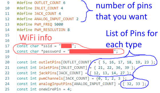
- Modify the code as such:
- First enter the number of respective Pins that you want. Make sure that this is the right number, as errors will result in crashes or non-functioning Pins !
- Enter your WiFi info, e.g. WiFi name and password
- Enter the GPIO-Numbers (example Pinout diagram) that you want to use for each purpose. Watch out for the following caveats:
- if you want to use the Serial interface (UART) for debugging, don't use GPIO pins 1 and 3, as this will disable the Serial interface
- GPIO 34-39 can only be used for INLET
- they also have no internal pull-up or pull-down resistors
- ADC2 Pins can NOT be used as Analog Inputs
- only available when WiFi is off
- Upload the code to your ESP32 (don't worry, compiling takes quite a while)
- Start the Serial Monitor in the top right corner:
- In the bottom panel, klick "Serial Monitor" and set the Baudrate to 115200:
-
- restart the ESP32 by pressing the "EN" button on the front
- if everything works, you should see something like this after a while:
-
- When using windows you can then open the command console with WIN+R and typing in "cmd" and pressing enter
- type "ping" and afterwards the IP you just read and press enter:
-
- you should see some pings working with a time in the 100s of milliseconds
- then type "arp -a" and press enter
- You should see something like this:
-
- Note the "physical address" behind the previously encountered IP
- You can set your router to give this physical address a constant IP if you like, in my case it looks something like this:
-
- I entered the physical address we noted before and the IP it should get
- restart the ESP32 again by presing the "EN" button on the front
- now I get this in the Serial Monitor:
-
- We now know the IP of the ESP32 and can continue to ReefPi
- Go to Configuration->Drivers and add an ESP32 driver:
-
- Give it a nice name
- enter the IP-address of the ESP32
- enter the COUNT of OUTLET pins that you have entered in the code before
- in my case I have the standard number of 6 outlets
- proceed the same with INLET, PWM and Analog Input
- go to Configuration->Admin and press reload
- go to Configuration->Connectors and define your connections:
-
- Note that the "Pins" 0 to (Count-1) correspond to the order in the GPIO List we have defined in the ESP32 code:
-
- Since I connected my example to GPIO 36 I have to use Inlet "Pin" 2
- Analog Inputs are special, since the Analog Input "Pin" 0 is always redirected to the DS18B20 OneWire protocol:
-
- That is why we had to increase the number of Analog Input in the driver by 1
- The other Analog Inputs can then be accessed with "Pins" 1, 2, etc. once @Ranjib updated the code:
-
- Jacks work like OUTPUTS and INPUTS again, even though you have to manually type the pin number:
-
- Go to Configuration->Admin and Reload again























