Led hacking help for robotank

Cantankerous

New Member
View Badges
Joined
Dec 20, 2022
Messages
6
Reaction score
20
Location
Western Australia
Rating - 0%
0   0   0
Hi folks.

Looking at trying to control an array of 6 xr15 knockoffs, actual brand name was 'intelligent ocean r80. Hoping to do so via pwm from my brand new robotank boards, (printing cases as I type!)

I'm from a software background, tiny bit of electronics knowledge but a lot to learn, hopefully this is the project to kick-start that.

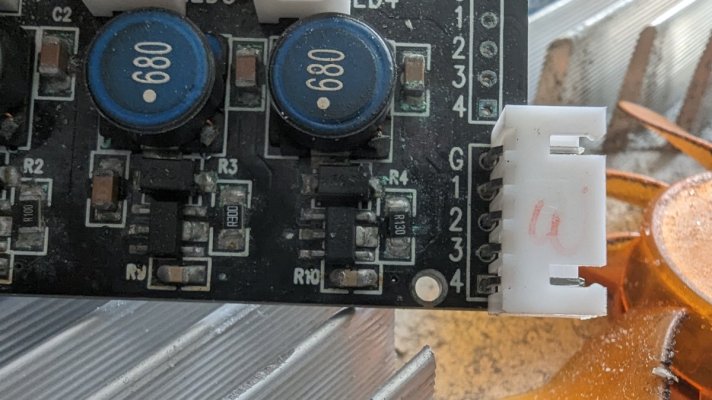
First pic is the light with the cover off. To the left are the controller boards, wifi etc. My hope is actually to ditch all that as its interface is borderline unusable anyways. And instead just run a PWM signal to the two boards to the right of the heatsink that each supply four channels for the lights. Ultimately hoping to scrap the rest of the case etc and mount the led pucks, heatsink and boards into a custom low profile canopy that's being built.

PXL_20221220_060735572.jpg


I've got my hands on an oscilloscope, although have next to no idea what I'm doing with it yet, and believe I'm picking up a pwm signal coming in via the headers circled below. It's definately a square wave pattern, but where I'm getting tripped up is that the pattern seems to be the same on each header, even when the channels are running at very different outputs.
PXL_20221220_060821191~2.jpg


The spec sheet I can find for the chip that I believe is doing to work here (mt7201 continuous mode stepdown driver, link below) seems to indicate the chip can be driven either by voltage or pwm.

I'm reading up on how to decipher the electronics ATM, but my hope is I can simply unplug the old control boards, and send a PWM signal from the robotank to each of these channels instead. If any kind soul with a better grasp of electronics than me want to say if that sounds like the right direction to go, or what I should be reading up on instead, I'd be extremely grateful.

Part two of this will then be, can I just daisy chain these lights with the pwm signal, or does something like that generally require a dedicated repeater/distribution board to split the signal between all lights?

Cheers folks!

https://www.google.com/url?sa=t&source=web&rct=j&url=https://pl-1.org/getproductfile.axd?id=13915&filename=MT7201.pdf&ved=2ahUKEwjS-4SQqoj8AhV-7zgGHXn-Df0QFnoECBEQAQ&usg=AOvVaw0rHK_6BVZ28gK8xxR4CjV9
 
Last edited:

Sral

Valuable Member
View Badges
Joined
May 2, 2022
Messages
1,006
Reaction score
976
Location
Germany
Rating - 0%
0   0   0
Whoooo, hacking electronics is right up my alley :beaming-face-with-smiling-eyes:

Similar-ish background, physics with a few courses in basic experimental electrical physics, one in measurement systems and a few in semiconductor and solid-state physics. So I do know the basics, but that often doesn't mean that much in practice ^^

I would carefully agree with you though, that Connector with G and 1-4 probably means Ground and 4 signals for the 4 drivers. Whether those 4 drivers represent 4 channels or just 2 Channels with 2 lamps each I cannot say. You could test this though with different methods:
  • Set the magnitude for 3 of the 4 channels to zero and the other one to 50%
    • look at the voltage on those 4 signal wires vs Ground
      • either with a multimeter using all VDC, VAC and PWM Frequency and duty-cycle setting
      • or with your oscilloscope in DC measurement mode
    • if only 1 wire carries meaningfull signal, it's 1 wire per channel and driver board
    • if 2 wires carry the same signal, it's 2 wires per channel and driver board, and the load is simply split between 2 drivers
    • if 3 wires carry the same signal, it's probably a special channel that has more load and requires 3 drivers to handle it, e.g. if the white channel has more LEDs than all other channels
    • If all 4 wires carry the same signal, the same applies and you should test the other board in the same manner
    • If you have identified the channels this way, you can try setting the magnitude of this channel to 100% and see how the signal changes.
  • you can also simply turn off the light and measure resistance across the signal pins on the WiFi-control board
    • BUT, this can lead to destruction of components if, for example, the system is sensitive to voltage and your multimeter simply decides to drop 9V on it
    • this is probably unlikely, but you never know, so I would leave this method to last and definitely unplugg and thereby safe your driver boards.
If every driver has its own distinct signal you should be able to simply daisy chain them together using the second G,1-4 pins that do not have a connector soldered to it.

About the driver chip mt7201, it does look promising.
Only problem I can see: you can drive it both by a DC voltage and PWM and the PWM voltage even affects the light output. So you would first need to find out how the board is set up and I'm worried about the Capacitor C2 in your above picture ... this might either simply be a 4.7µF bypass capacitor, as recommended in the datasheet, or it might be there to smooth the input PWM to a DC that is then applied on the adjust pin.

If it's the latter, you will only be able to (slow)start the light with 25% intensity, not smoothly anywhere between 1% to 25%. It's hard to analyze this on the hardware itself, unless you make a map of all the lines on one of the mt7201 drivers to all components, but you could simply start the light with the original WiFi driver and try to judge if you can set 1-10% light intensity (e.g. barely visible), or if it slowstarts immediately to 25%.
 
OP
OP
Cantankerous

Cantankerous

New Member
View Badges
Joined
Dec 20, 2022
Messages
6
Reaction score
20
Location
Western Australia
Rating - 0%
0   0   0
Just a part update, want to thanks hugely for that. That gives me a great list of things to try out next ;)

I've been rereading it alongside the datasheet and tracing out the circuit trying to figure out how everything is connecting, although ten odd years of marine environment exposure is not helping with accurate resistance readings.

It looks like the layout very closely mimics the layout from the data sheets, header pin 4 runs to adj on the mt7201. However it then also runs to the capacitor at r10 before ground. (Am assuming that's a capacitor despite being numbered with an r, looks like one and showing open circuit across it.)

Capacitor c2 on the other hand is an absolute mystery. Its bottom pin connects to isense on the mt7201 and one of the pins going to the leds, but I've not been able for the life of me been able to figure out where the upper pin connects to.

More work to be done including getting voltage reading with it running (newborn in the house is setting the schedule ATM) but I am starting to wonder if these are voltage controlled if r10 is smoothing pwm into a dc voltage (sorry not sure how that would look in a circuit but assuming something like that?)

Can't fire up the lights just ATM (will soon) but memory is telling me that when set to 1 percent via the app they did have a minimum threshold, which would also like up with being DC from what I understand. Also would line up with some very early tests I made when first got the oscilloscope seemed to have the exact same square wave pattern. I was looking for changes in duty cycle and even on different brightness percentages they were all the same. In hindsight that could have been an autoranging voltage messing me up, but need to confirm.

Good news is robotank has options of supplying DC control as well as pwm it seems, but wondering if I'm going to have a headache splitting a DC signal 6 ways.

But getting ahead of myself, will keep testing at next available opportunity, try to confirm if it is DC or not, then work out where to from there. Thanks again for your help, it's been invaluable and saved me a heap of head scratching. Still plenty of terminology to learn, but just knowing terms to google was a massive step forward for me.
 

Attachments

  • PXL_20221221_002908831.jpg
    PXL_20221221_002908831.jpg
    155.1 KB · Views: 43

Sral

Valuable Member
View Badges
Joined
May 2, 2022
Messages
1,006
Reaction score
976
Location
Germany
Rating - 0%
0   0   0
Just a part update, want to thanks hugely for that. That gives me a great list of things to try out next ;)

I've been rereading it alongside the datasheet and tracing out the circuit trying to figure out how everything is connecting, although ten odd years of marine environment exposure is not helping with accurate resistance readings.

It looks like the layout very closely mimics the layout from the data sheets, header pin 4 runs to adj on the mt7201. However it then also runs to the capacitor at r10 before ground. (Am assuming that's a capacitor despite being numbered with an r, looks like one and showing open circuit across it.)

Capacitor c2 on the other hand is an absolute mystery. Its bottom pin connects to isense on the mt7201 and one of the pins going to the leds, but I've not been able for the life of me been able to figure out where the upper pin connects to.

More work to be done including getting voltage reading with it running (newborn in the house is setting the schedule ATM) but I am starting to wonder if these are voltage controlled if r10 is smoothing pwm into a dc voltage (sorry not sure how that would look in a circuit but assuming something like that?)

Can't fire up the lights just ATM (will soon) but memory is telling me that when set to 1 percent via the app they did have a minimum threshold, which would also like up with being DC from what I understand. Also would line up with some very early tests I made when first got the oscilloscope seemed to have the exact same square wave pattern. I was looking for changes in duty cycle and even on different brightness percentages they were all the same. In hindsight that could have been an autoranging voltage messing me up, but need to confirm.

Good news is robotank has options of supplying DC control as well as pwm it seems, but wondering if I'm going to have a headache splitting a DC signal 6 ways.

But getting ahead of myself, will keep testing at next available opportunity, try to confirm if it is DC or not, then work out where to from there. Thanks again for your help, it's been invaluable and saved me a heap of head scratching. Still plenty of terminology to learn, but just knowing terms to google was a massive step forward for me.
Well, splitting a DC signal 6 ways should not be a problem, since the ADJ-Pin has a large input resistance (120 kOhm), so you should be able to feed a near infinite amount of ADJ-pins in parallel.
If you can daisy chain the lights, you don't even have to split it yourself, just use 4 separate channels on RoboTank and hook them up to one connector.

Regarding the lines:
  • if pin4 runs to the ADJ, try finding out if there is also a resistor in between, as that makes a huge difference:
    • 1671621632126.png
    • if you have that R_ADJ resistor, it slowly feeds the C_ADJ capacitor, smoothing the PWM out, depending on the values of C_ADJ and R_ADJ and the PWM frequency
    • if you do not have that R_ADJ resistor the C_ADJ capacitor is fed directly by your input signal and the PWM is not smoothed out, but has increased slowstart time (see the datasheet)
  • the C2 capacitor is possibly the C_IN, although I'm not sure
    • it should be connected to GND on both the signal and power input
    • the other side is connected to I_SNS, as you said
      • but I assume that it is actually connected to V_IN, which in turn is connected by the very little R_SNS resistor to I_SNS
  • having exactly the same wave pattern on all light intensity settings does also suggest a DC smoothing, where the resulting DC voltage is dependent on the voltage of the PWM pulse, not the duty cycle
  • One thing I'm concerned about is the different resistor on each of the drivers ... they seem to be all over the place. One is R100, the next R300 and another one R130. Looks strange.
As an alternative to measuring with a multimeter in resistance setting you can also try to sketch a circuit diagram by tracing the PCB lines visually. Since you only have a few components on each driver that should be possible and you can compare this with the multimeter resistance readings to check if you made a mistake.

In case it realy is DC smoothing and you would like a PWM approach you might be able to desolder that R10 "capacitor" and thereby disable the smoothing. I have to caution though, since you would be forced to use a PWM frequency of 500 Hz or lower, which might result in visually noticeable flickering (this would however be attentuated by the inductor L, so you might also be good). So if you go down that route you would need to check this first, for example by trying to feed a pwm signal (with a maximum of 1.2 V mind you) directly to the ADJ-Pin using a measurement probe with a sharp tip (and connecting GND the usual way), bypassing any DC smoothing non-destructively.
 
OP
OP
Cantankerous

Cantankerous

New Member
View Badges
Joined
Dec 20, 2022
Messages
6
Reaction score
20
Location
Western Australia
Rating - 0%
0   0   0
Thanks again. Had the chance today to power it up and from what I can make out its looking voltage controlled. Below are the 8 channels 0-100% and corresponding voltages read from pins (8 pins in total as there are two of these driver boards)

WDUGBVRY
%510010020541005118
V0.163.273.270.161.773.2600

Manually controlling one circuit and ramping it up and down sees the same, voltage increases with brightness %, duty cycle doesn't shift.

Fly in my ointment number 1 is the r/y channel but this could be a dead channel, these lights do have red LEDs which illuminate at startup, but none are illuminating at that setting. Playing with another set of lights the last two channels are also non responsive when changing profiles so who knows.

Have tried to visually map out the tracks but the boards have some kind of extra layer between the components and the board itself that hides almost all the tracks, can't see a way to get it off without desoldering unfortunately. There's a few tracks visible on the back of the board, but not enough to be able to make sense of things unfortunately which has left having to try to trace out with multimeter.

No sign of a resistor in play between pin and
Adj, although it could be located on the controller board. I've had a poke around on there but it's a whole other level of complexity. However that unearthed fly in ointment number 2. A large prominent label on the pins that connect to the led driver boards that states PWM OUT....

I've fired up the oscilloscope, and whilst I truly have no idea what I'm doing, Ive calibrated probes to get a clean square wave from the generated signal, then grounded to earth pin in header, tip to other pins.

Pic 1 is results for a channel running 100%. Signal is all over the shop, but Vavg steady on 3.53v
PXL_20221222_081109814.jpg


Pic 2 is channel at 0%. Signal all over the shop, Vavg 0.0v
PXL_20221222_081219842.jpg


Pic 3, Goldilocks channel, 79% brightness. Signal still crazy, Vavg 2.82v
PXL_20221222_081159951.jpg


Weirdly though I noticed that when ground is removed the signal clears up significantly.
PXL_20221222_075744452.jpg

However all channels have the same 50/50 duty cycle, +/- 1 or 2 points.

Would I be mad to go ahead assuming this is a voltage driven circuit? My sampling methods are not great, multimeter I'm pretty confident with but it's only a cheapy on a pretty corroded board. Oscilloscope Ive got a lot to learn, take anything I say from there with extreme caution, but I just can't see how it could be a pwm signal being sent through those pins, despite what the control board says.

Just realised haven't put pictures of control board. Sorry my post is way too long already but will just finish with quick snaps of what I'm seeing on the other side. Next up I'm going to look into smoothing you've mentioned, will need to do some more reading there. Once I've unpacked that a bit hopefully will be able to try passing a voltage from robotank using a 0-5v analog channel I'm thinking. Is more than the 3.5v currently being passed but am hoping there will be a software limit I can set that'd be up to the task. The journey continues!
PXL_20221222_080521515.jpg
 

Sral

Valuable Member
View Badges
Joined
May 2, 2022
Messages
1,006
Reaction score
976
Location
Germany
Rating - 0%
0   0   0
Again, you're very welcome.

How did you measure these voltages ? With the oscilloscope, or with a multimeter ? If its the multimeter I would always record both DC and AC values, since the DC measurement has an internal low-pass that smooths out any PWM to a constant DC voltage (basically the average), whereas the AC measurment gives you info on the PWM (basically the amplitude combined with duty cycle).

That PWM OUT signal does indeed look very strange. How exactly did you measure it ?
Did you measure it on the driver or Main control board ?
If the later: Was the driver board connected while you measured ?

Both having the driver board connected and not connected can have an effect, depending on how the Main control unit operates. If it's not connected you can get reflections on your oscilloscope, which is very high input impedance, or you can get distortions from other channels. If it is connected, you might actually see the driver board manipulating the voltage with that capacitor, if its connected.
Both of these could very much lead to this spikey behavior.

You could try connecting a small load, e.g. a 2-5k resistor between a PWM out and GND and measure the voltage over this load with your oscilloscope.

BTW, removing the Ground probe does, if I'm not mistaken, give you a kind of AC coupled measurement. If your oscilloscope has this kind of DC/AC setting, try comparing this.
 

oreo54

5000 Club Member
View Badges
Joined
Sep 18, 2017
Messages
5,633
Reaction score
3,464
Rating - 0%
0   0   0
Thanks again. Had the chance today to power it up and from what I can make out its looking voltage controlled. Below are the 8 channels 0-100% and corresponding voltages read from pins (8 pins in total as there are two of these driver boards)

WDUGBVRY
%510010020541005118
V0.163.273.270.161.773.2600
Ok Mr. Guess here.
My non-o-scope take on this is:
No it is not "voltage controlled"
That data points to 3.3V PWM with the meter "averaging" the voltage. Check for peak.
The other component.. more than likely the frequency is around (slightly below) 500Hz..
Oddly the drivers pwm frequency range is either <500Hz or optionally >10kHz AFAICT

There are oddities above but the main "evidence" is the 2 at 100% and close to 3.3V
50% 1.77 close to the predicted average voltage/time of 3.3/2.


You can "analog dim" using 0.3v to 2.5V at the dim input.

Ignoring the fans for the moment the only important component is the driver board.
Blue block should be 40v (or less) your dc input to the drivers.

pxl_20221220_060821191-2-jpg.2941219


Technically you can throw all of it out and use LDD-H's on the end ;)
 

oreo54

5000 Club Member
View Badges
Joined
Sep 18, 2017
Messages
5,633
Reaction score
3,464
Rating - 0%
0   0   0
Fyi you can determine the driver current using .1/R(sense)
From the ones I can see ..
R4 = R130 = .1/.13 = 770mA
R3 = R300 = .1/.30 = 330mA
Approx.

Will come in handy if you dump the orig driver boards.
 

Sral

Valuable Member
View Badges
Joined
May 2, 2022
Messages
1,006
Reaction score
976
Location
Germany
Rating - 0%
0   0   0
Ok Mr. Guess here.
My non-o-scope take on this is:
No it is not "voltage controlled"
That data points to 3.3V PWM with the meter "averaging" the voltage. Check for peak.
The other component.. more than likely the frequency is around (slightly below) 500Hz..
Oddly the drivers pwm frequency range is either <500Hz or optionally >10kHz AFAICT

There are oddities above but the main "evidence" is the 2 at 100% and close to 3.3V
50% 1.77 close to the predicted average voltage/time of 3.3/2.


You can "analog dim" using 0.3v to 2.5V at the dim input.

Ignoring the fans for the moment the only important component is the driver board.
Blue block should be 40v (or less) your dc input to the drivers.

pxl_20221220_060821191-2-jpg.2941219


Technically you can throw all of it out and use LDD-H's on the end ;)
Good idea, one possibility might be to throw those drivers out and drive them using LDD drivers. Problem there is to find out how much current each channel takes, but that should be easily possible from those SMD resistors.
Good thing you mentioned this though, this gave me the idea, that these SMD resistors are very likely the sense resistors that can tell us, how much current each channel is supposed to take.

@Cantankerous Something I have just noticed with your scope ... your first measurement of the "PWM" is too fine in time. Your period is about 34µs, giving you a frequency of 28kHz. Either this is realy your PWM frequency OR this is actually just the switching frequency of some component that adds noice on top of your PWM. Please measure this again and try timescales between 2 ms per division and 2µs per division and see which gives you the nicest signal.

As a reference you can see if your multimeter has a PWM/Frequency setting. That would give you an idea to what timescale you should probably be looking at.

When you measured without grounding you get a 90V peak voltage at a period of 20ms, equaling 50 Hz. That sounds more like your AC power line and is probably not a real signal ... only noticed this just now ^^

Next up: all these different SMD (surface mount device) resistors are probably the RSNS resistors that define how much current each driver outputs to its LEDs. I just had a look: R100 means 0.1Ohm, exactly what the datasheet mentions for RSNS. R300 is 0.3 Ohm, so its a channel that needs less current for full power because it has less LEDs I wager. This would enable us to drive your LEDs with the LDD drivers (constant current LED driver circuits if I'm not mistaken) that @oreo54 mentioned.
 
Last edited:

Sral

Valuable Member
View Badges
Joined
May 2, 2022
Messages
1,006
Reaction score
976
Location
Germany
Rating - 0%
0   0   0
Fyi you can determine the driver current using .1/R(sense)
From the ones I can see ..
R4 = R130 = .1/.13 = 770mA
R3 = R300 = .1/.30 = 330mA
Approx.

Will come in handy if you dump the orig driver boards.
Aaaaaand you were faster ^^

This only applies strictly for an ADJ voltage of up to 1.2V if I'm not mistaken. If the signal voltage is higher, these currents would be higher as well. Shouldn't happen though, as this would lead to an overcurrent on the driver with the 0.1 Ohm resistor.
 
Last edited:

oreo54

5000 Club Member
View Badges
Joined
Sep 18, 2017
Messages
5,633
Reaction score
3,464
Rating - 0%
0   0   0
With the PWM plug removed all drivers should go to 100% when the light is energized.
Easy enough to measure the actual current.

I gave up on the rest when I read

"Depending on the control frequency, this will provide either a continuous or a gated output current"

There are a bunch of charts showing deviations of the current based on input voltage (DRIVE power), number of leds in a string and choke frequency.

I've always ignored any attempts at using the analog dimming in these. You can do the same with SOME LDD's but using 3.3 or 5V PWM is just simple and uncomplicated.
 
Last edited:
OP
OP
Cantankerous

Cantankerous

New Member
View Badges
Joined
Dec 20, 2022
Messages
6
Reaction score
20
Location
Western Australia
Rating - 0%
0   0   0
Thanks folks I have some serious reading to do. Will hopefully get a window to do some more testing tomorrow, but can answer a few questions now. All readings were taken with the driver boards plugged in, essentially all of the light was hooked up and operating, and I was just taking readings.

Measurements were taken at the control board side of the wires, with driver boards still attached.

Multimeter is just an ultracheap one, no pwm capabilities. Frustratingly all of my nicer meters seem to die after a few years, while this one cheap junk one that came in a car tool kit seems to be immortal, must be pushing 30 years old now I'd say. Getting a new meter is on to do list, but don't have anything available to hand ATM unfortunately.

Voltage readings in table from multimeter in DC. The Vavg reading in screenshots are from oscilloscope.

Blue block is power from transformer.

Have to admit, getting in real close with these boards to try to trace tracks I am starting to wonder about if I should bin entirely and put in something new. Will have to see about costs, 8 channels for six sets of lights adds up pretty quick, but if nothing else I think I'll be laying them out in the hood so that I can pull and replace these boards without too much future hassle.

I did actually start with a broader timeframe on the scope, so can share a sample of that now, this is it at 5ms. I was messing with sampling trying to find anything approaching a smooth waveform, but will go through methodically in next testing session.
PXL_20221222_075707721.jpg
 
OP
OP
Cantankerous

Cantankerous

New Member
View Badges
Joined
Dec 20, 2022
Messages
6
Reaction score
20
Location
Western Australia
Rating - 0%
0   0   0
Strange, phone keyboard refused to come back after adding the picture... Carrying on...

I've got to take some time to sit down and digest the last few posts properly, apologies there's a fair bit of googling of electronics terms and concepts happening alongside all of this for me ATM. Will also just count out the number of LEDs on each channel as I think that may help some with what your saying about resistors and sizing of drivers for channels.

If I don't get a chance to jump back on in the next day or two just want to say thanks again and happy Holliday's/merry Christmas to everyone. I will be reading and learning more about this but just have a few mad days coming up running all over town.
 

oreo54

5000 Club Member
View Badges
Joined
Sep 18, 2017
Messages
5,633
Reaction score
3,464
Rating - 0%
0   0   0
Most digital vom just average voltage.
You don't really need a "pwm function".
Just disconnect the driver board and hook probes to the ground and one dim pin.
At 100% on should be " dc" and will define the signal (3.3 or 5v most common).

I see no reason ( physically nor economically ) to doubt that it is pwm control signal.
Almost all microcontrollers have native pwm io pins and the driver chips simplist dim protocol is <500 Hz 3.3-5v.

Not sure what is going on with the o scope but below is what I got using my computer sound card as an O scope and checking the waveform of a pwm output. Voltage was not calibrated. Dimming was 26-ish%
Second one was an attempt to "do dc" with an R/C filter.
5vpwmfilteredOhm.JPG


Fortunately the signal was low amperage since I didn't current limit the probes.

Which brings me to another point.
Looks like the PWM circuit has low mA (uA?) demand so won't stress the pwm output on most microcontrollers (20-40mA?).

Bottom line is one PWM output can dim numerous drivers.

BTW my attempt was at least 10 yrs ago soo I do not remember any settings.

ONE thing though is it looks to be 1ms divisions..you are set a 5ms
 
Last edited:

oreo54

5000 Club Member
View Badges
Joined
Sep 18, 2017
Messages
5,633
Reaction score
3,464
Rating - 0%
0   0   0
The mt7201 supports 500-20k frequencies,Depends on the output frequency of the control module,
Chip also supports .3 -2.5v analog (possible to use " smoothed" 3.3 or 5v digital pwm)
but would be highly unlikely.
Besides current goes to 200% of set point.
Afaict.
1-100% dimming.
Would just complicate using the digital outputs.

The high frequency pwm has it's own set of " complications". >10kHz to 1 Mhz
25% -100% dimming.

Using anything but <500Hz pwm would be err silly in my mind.

There seems to be no upside to anything else for LEDs.

What I don't see, being an amateur with this, is the "accepted" pwm voltage.
Best I can come up with.
 

Sral

Valuable Member
View Badges
Joined
May 2, 2022
Messages
1,006
Reaction score
976
Location
Germany
Rating - 0%
0   0   0
The mt7201 supports 500-20k frequencies,Depends on the output frequency of the control module,
That’s technically not what I asked, since I already know this ^^

I wanted to know how the mt7201 is driven in this specific lamp, because currently it looks like the circuit can’t dimm below 25%, which means either direct PWM above 20kHz or PWM smoothed to DC by the components next to the mt7201.
 

Tentacled trailblazer in your tank: Have you ever kept a large starfish?

  • I currently have a starfish in my tank.

    Votes: 24 29.6%
  • Not currently, but I have kept a starfish in the past.

    Votes: 18 22.2%
  • I have never kept a starfish, but I hope to in the future.

    Votes: 21 25.9%
  • I have no plans to keep a starfish.

    Votes: 18 22.2%
  • Other.

    Votes: 0 0.0%
Back
Top