LEDBrick - DIY LED Pendant with Pucks

theatrus

Valuable Member
View Badges
Joined
Mar 26, 2016
Messages
1,957
Reaction score
3,355
Location
Sacramento, CA area
Rating - 0%
0   0   0
8 year update: https://www.reef2reef.com/threads/ledbrick-diy-led-pendant-with-pucks.243746/page-12#post-10936553

New design underway

-------------------------------------------

(This is my summary of a project I did over the past ~ year, in condensed form, for others to be inspired by across the reef forum community. I'm also actively working on new components, LED emitters, and drivers, but the first series of posts is on the original version).

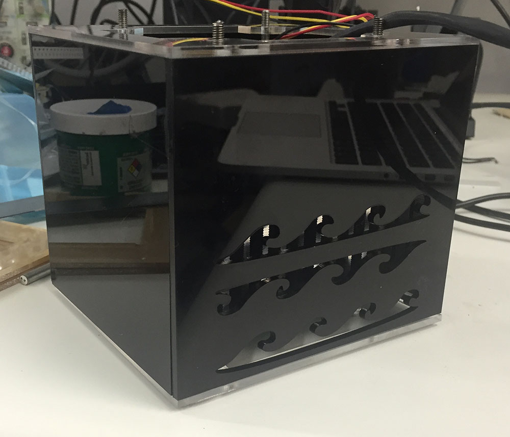
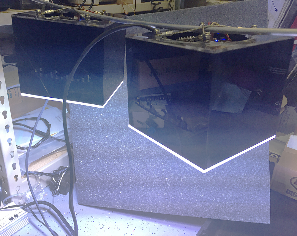
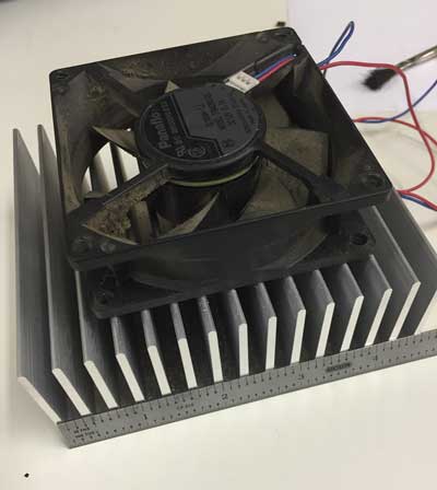
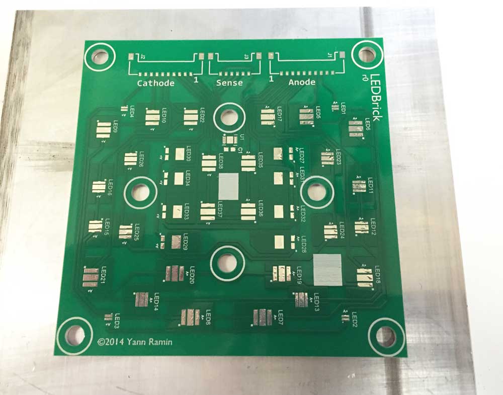
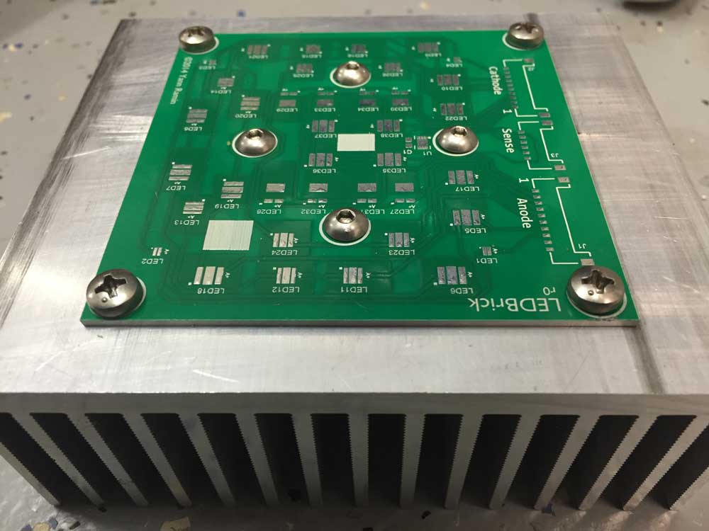
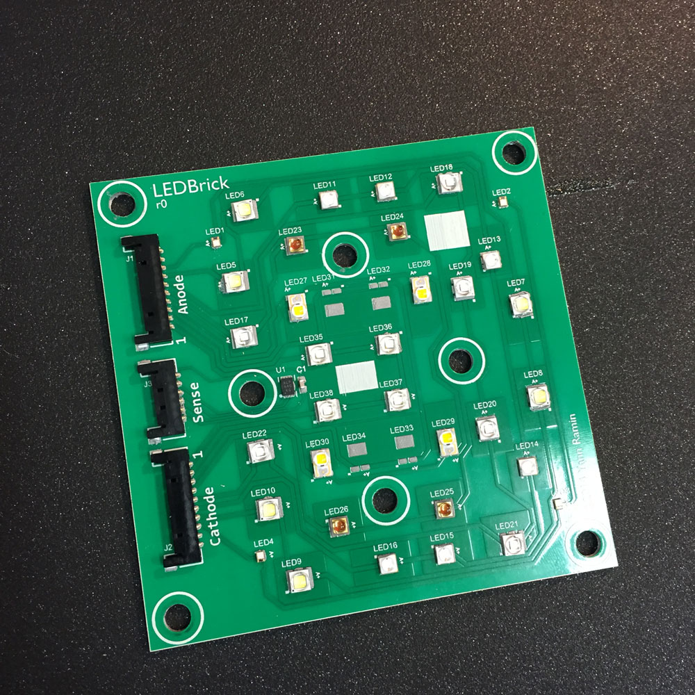
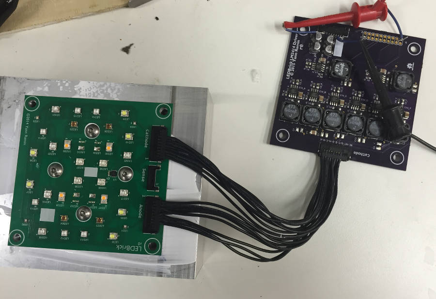
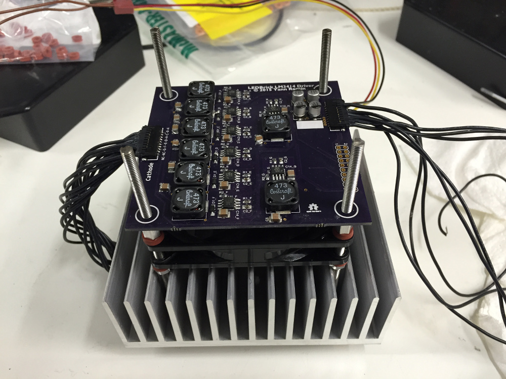
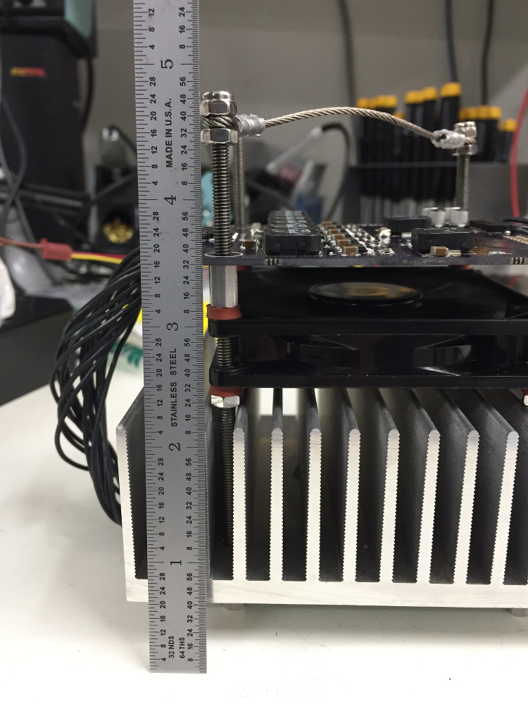
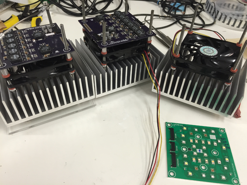
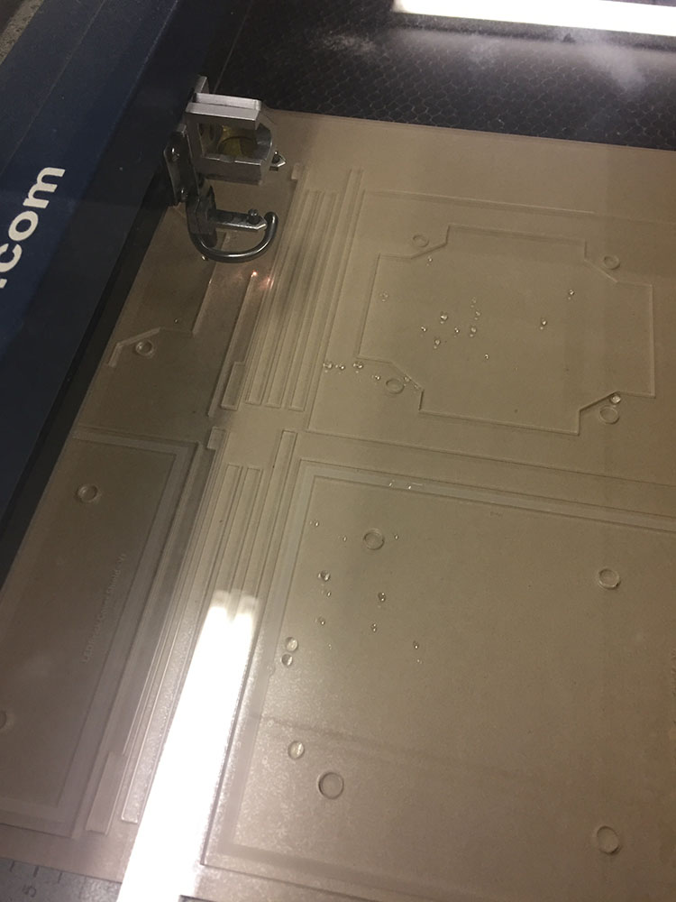
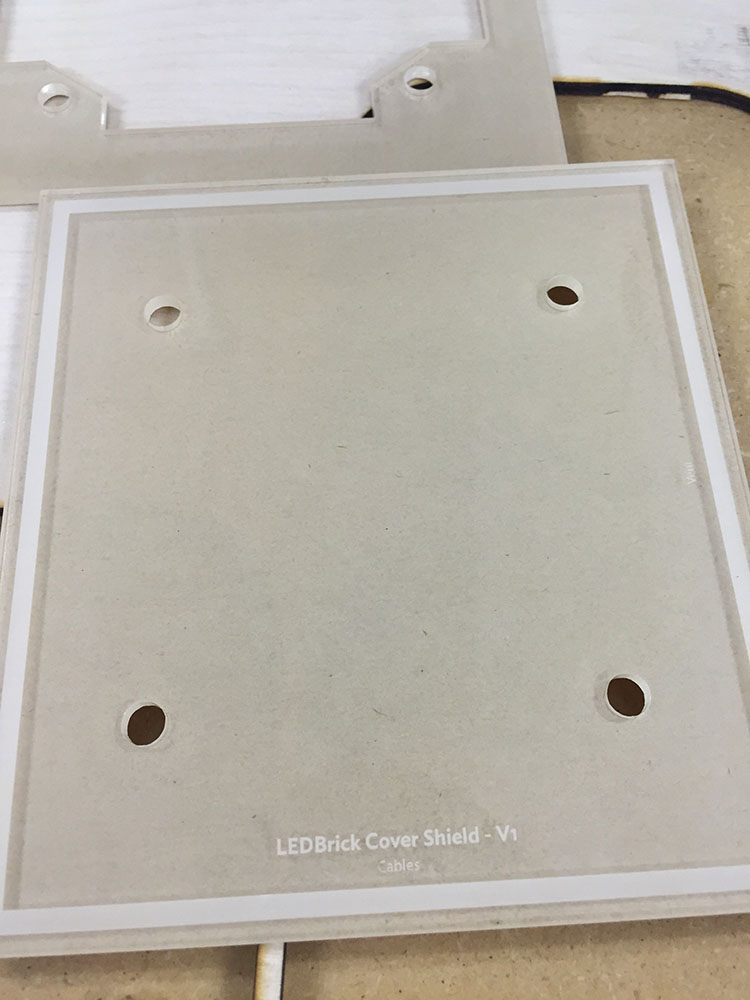
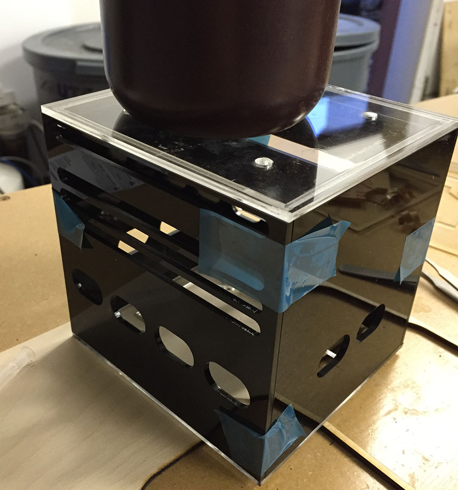
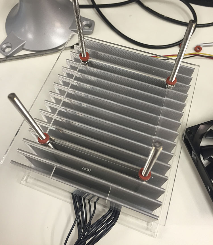
It all started with this concept - a squareish shaped LED "brick" in a pendant form. The mechanics were based around a 4.6in HeatsinkUSA serrated stock, and an 80mm fan.

fan-on-heatsink-sm.jpg


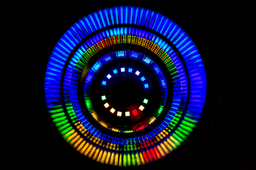
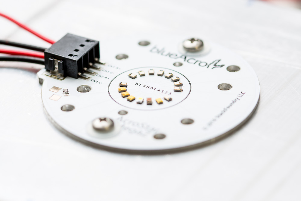
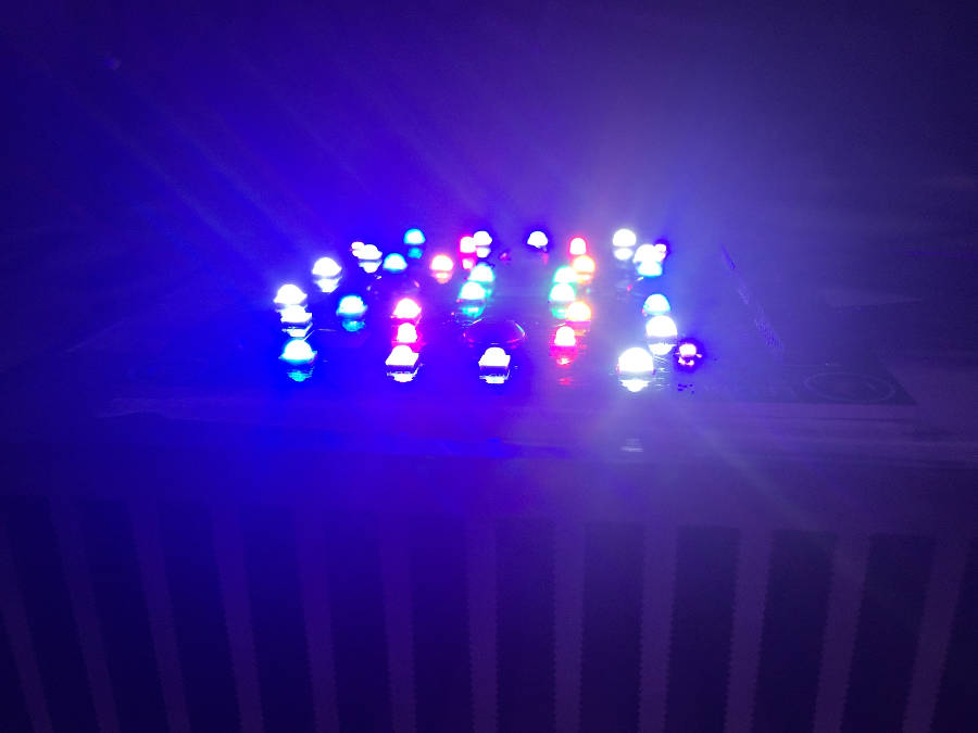
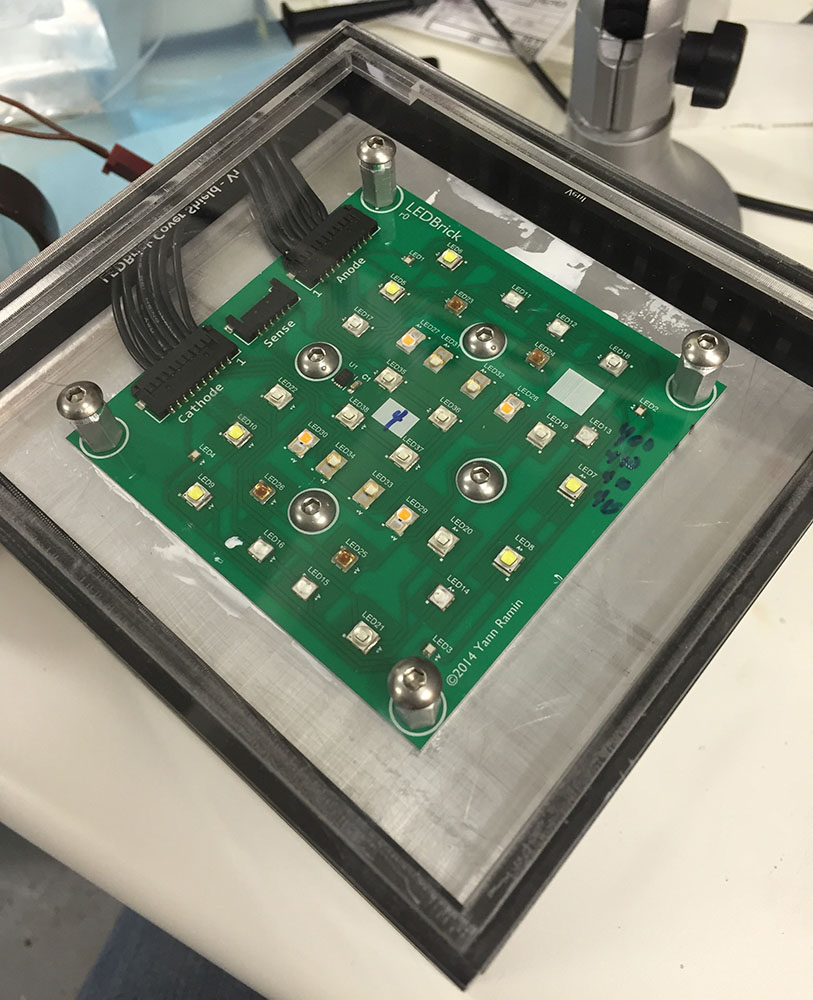
The LED arrangement I started with was this:

sch.png


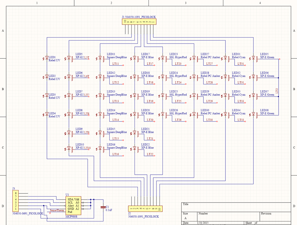
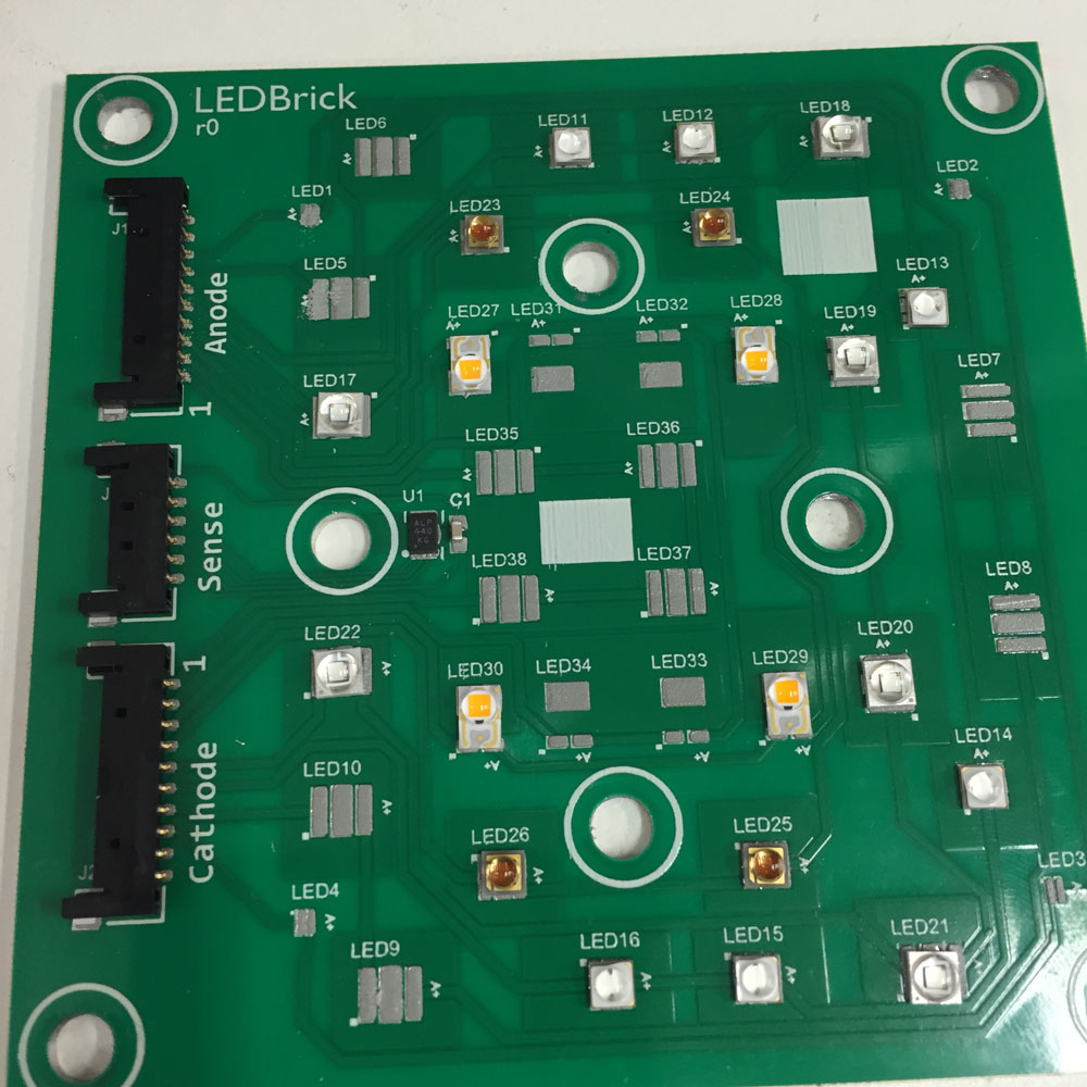
The pads and suggested LEDs are:
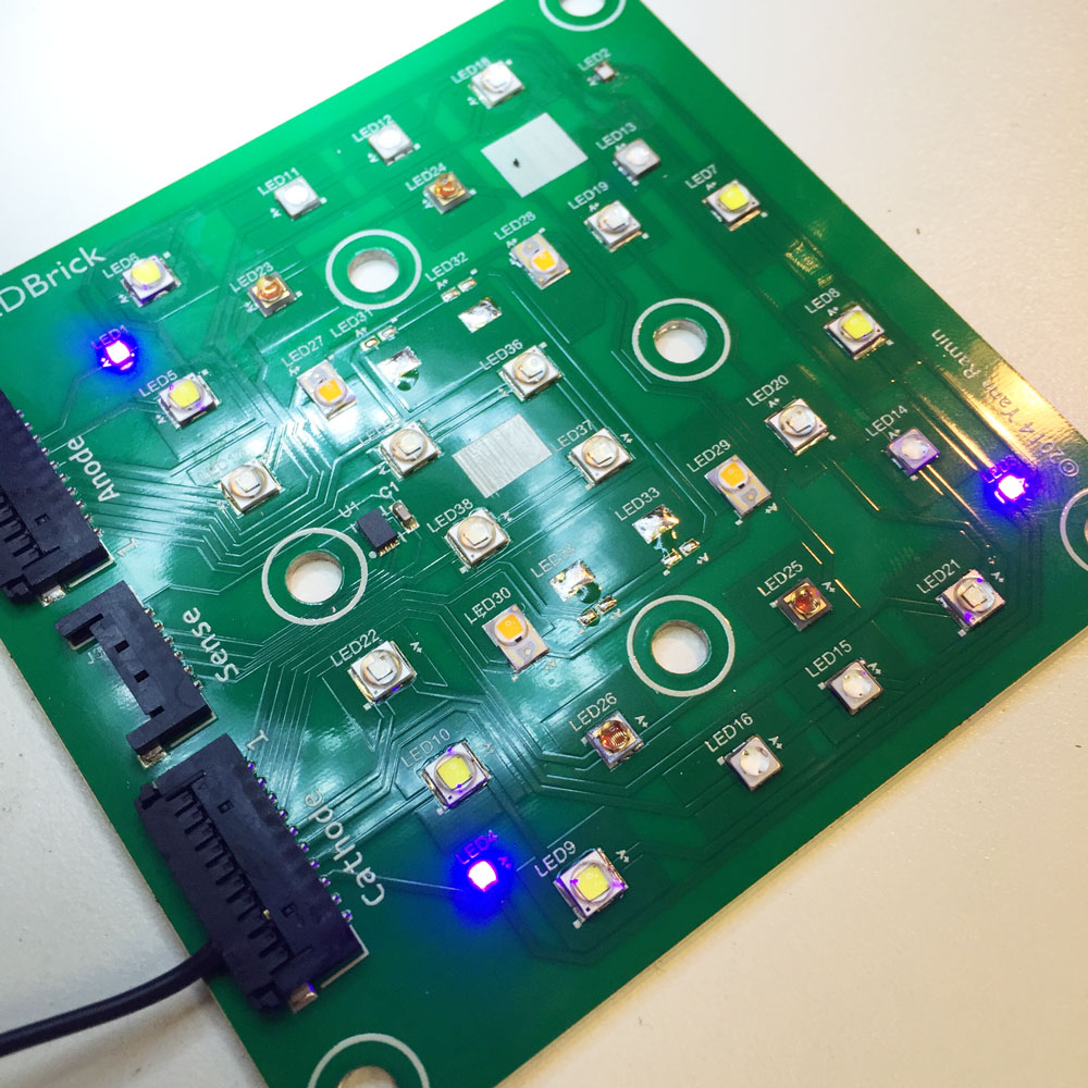
4 Rebel UV emitters (these are very expensive, but more efficient than the popular Chinese SemiLEDs emitters. They however do not have a primary optic - more on this later)
6 Cree XP-G(2) White emitters (or any Cree XP package)
6 Cree XP-E Blue emitters (or any Cree XP package)
6 Osram Oslon Squre Deep Blue emitters
4 Osram SSL Hyper-Red
4 Phillips Rebel PC-Amber
4 Phillips Rebel Cyan
4 Cree XP-E Green (or any XP)

ledbrick-board-top.jpg


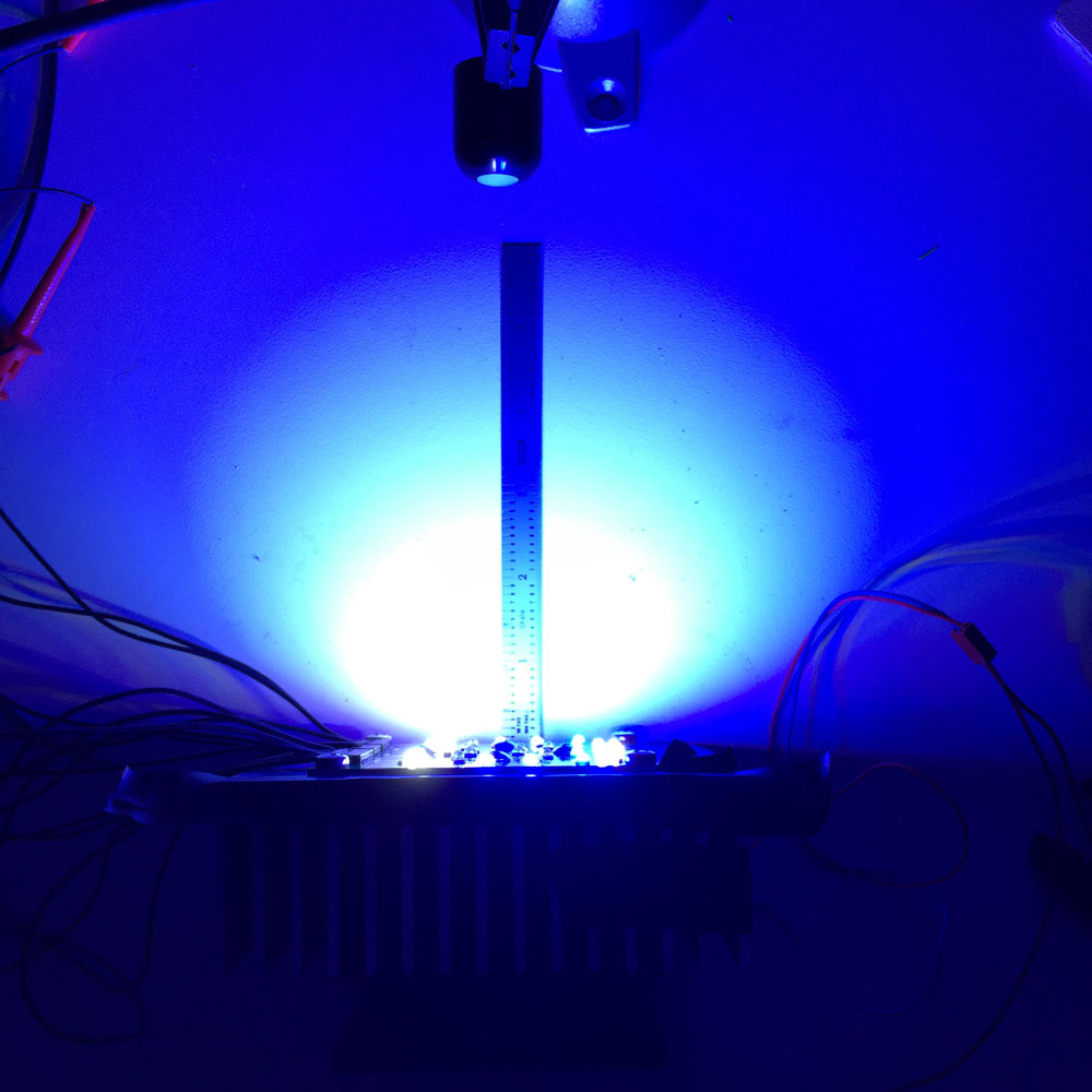
Why so many LEDs? Lower currents, higher efficiency, and future flexibility. Remember, this is not a build-cost efficient fixture

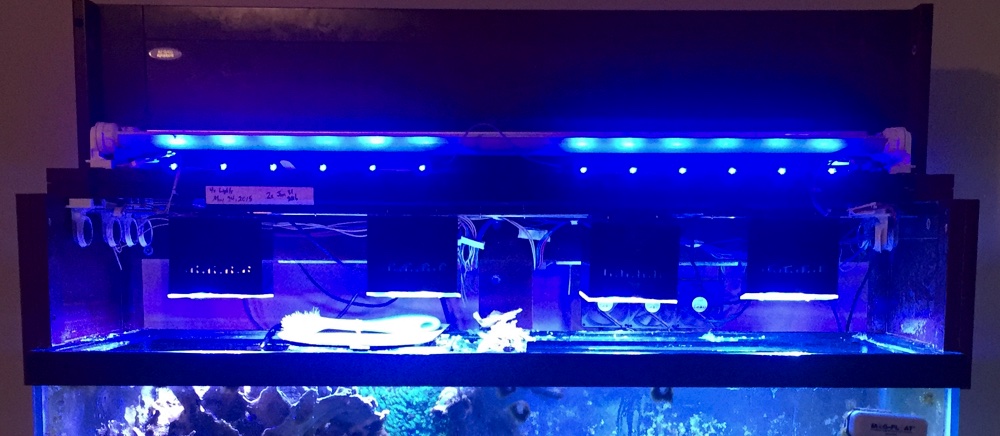
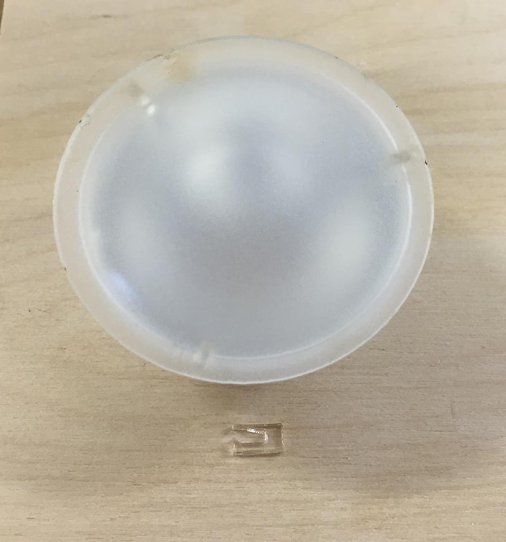
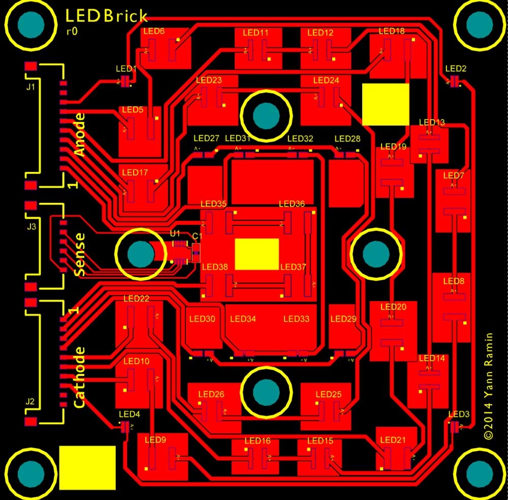
A downside to the large emitter count is the inability to provide secondary-optics, focusing the light tighter than 120 degrees from the primary optic. The emitters are simply too close together to use most commercially available lenses, which feature large footprints. I intend to run these pendents very close to the water, which would not need the use of an optic. My later designs use a reflector with very dense LED arrangements.

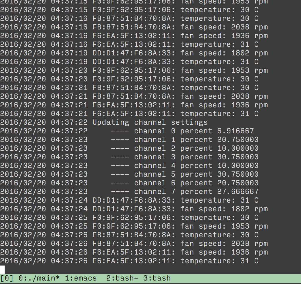
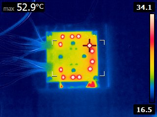
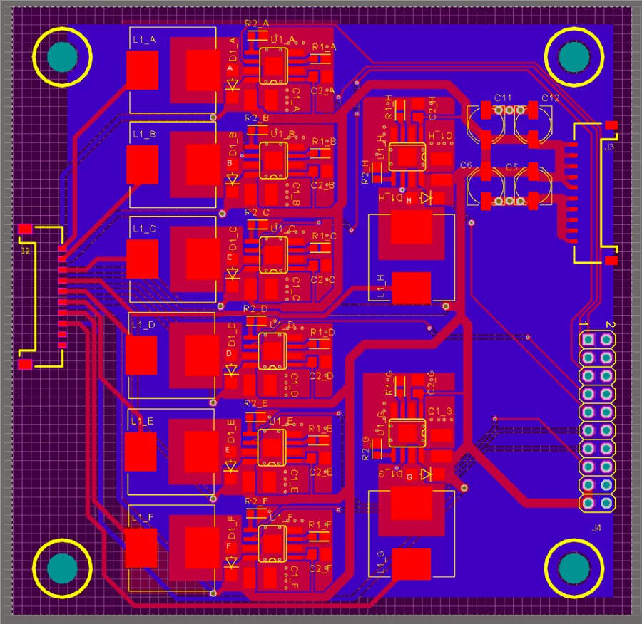
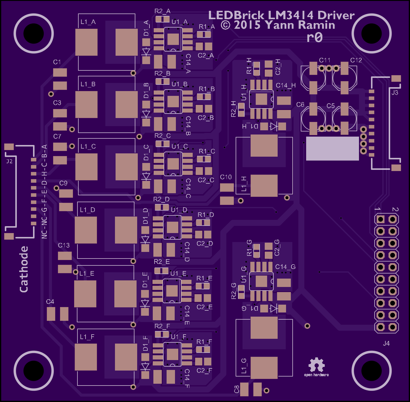
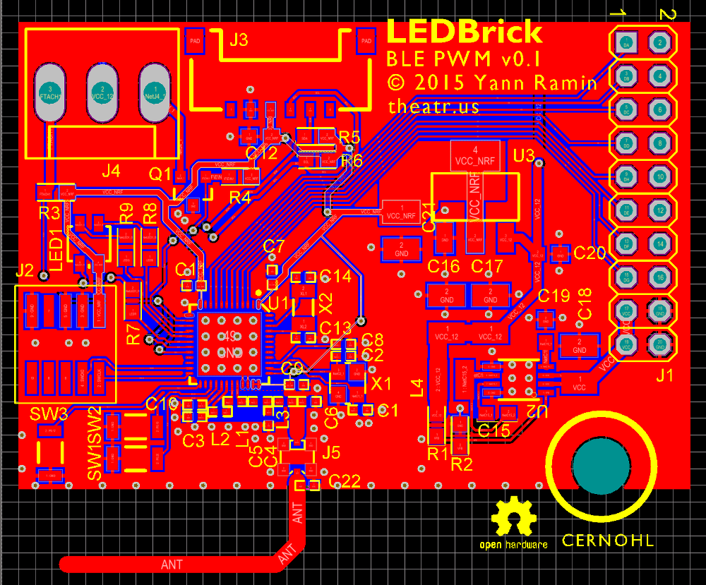
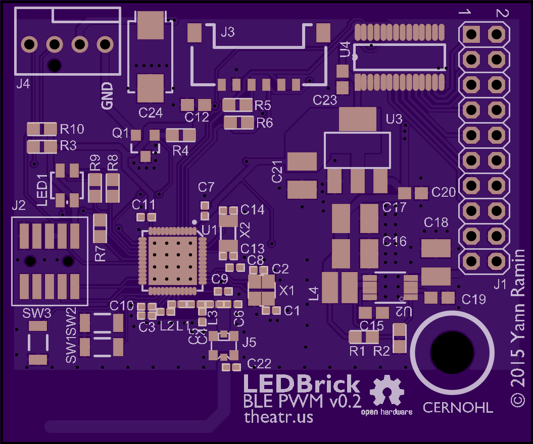
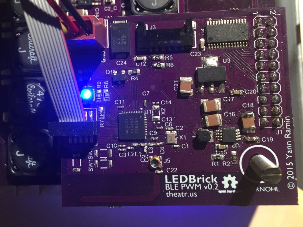
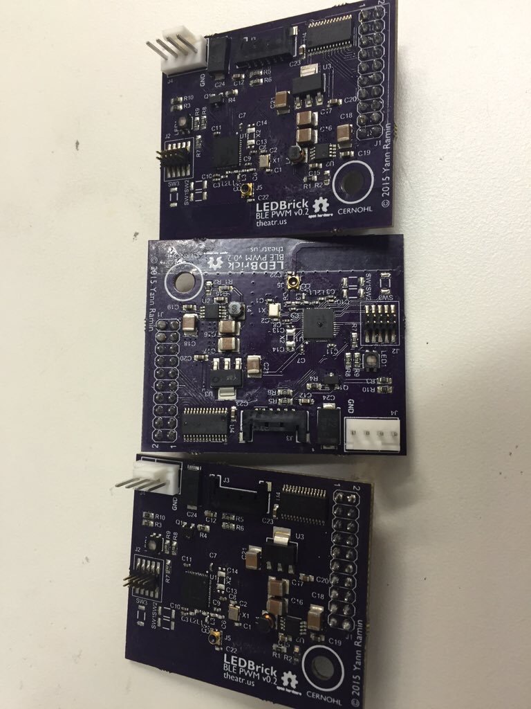
Also integral to the board is a Microchip MCP9808 I2C temperature sensor. The sensors ground pad is brought out to one of the mounting screws, in an effort to get a good thermal path.

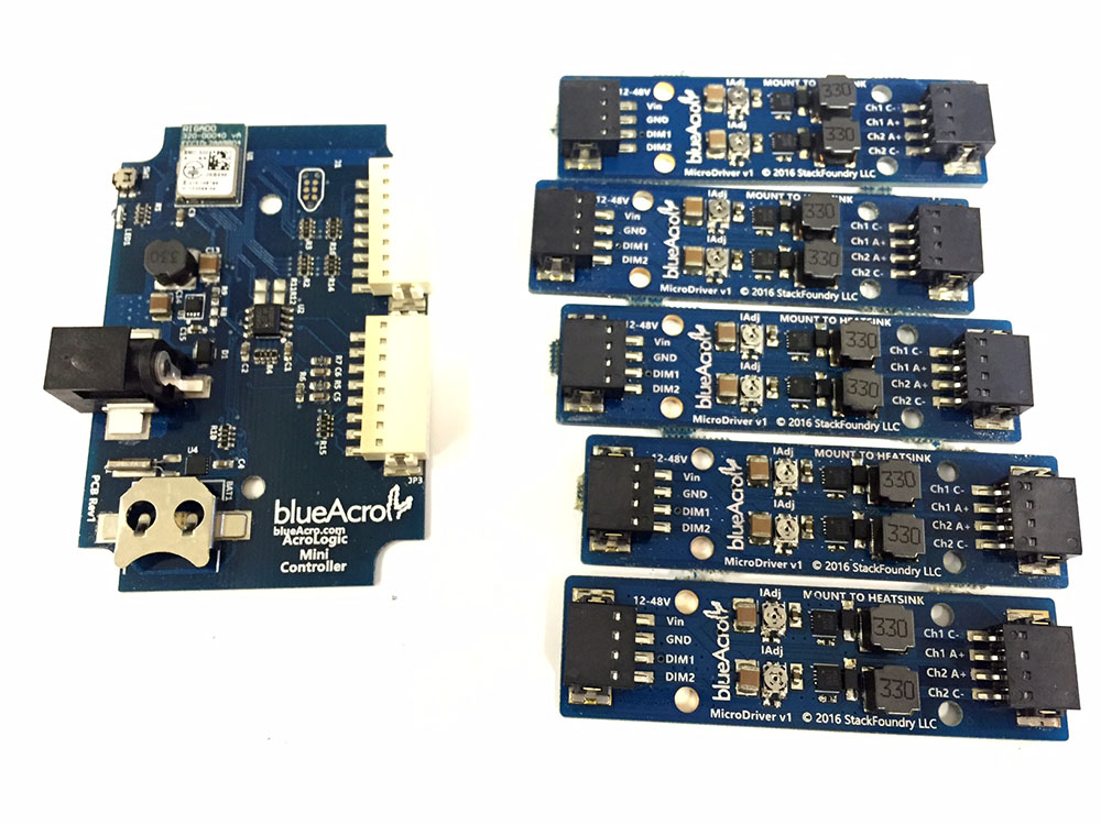
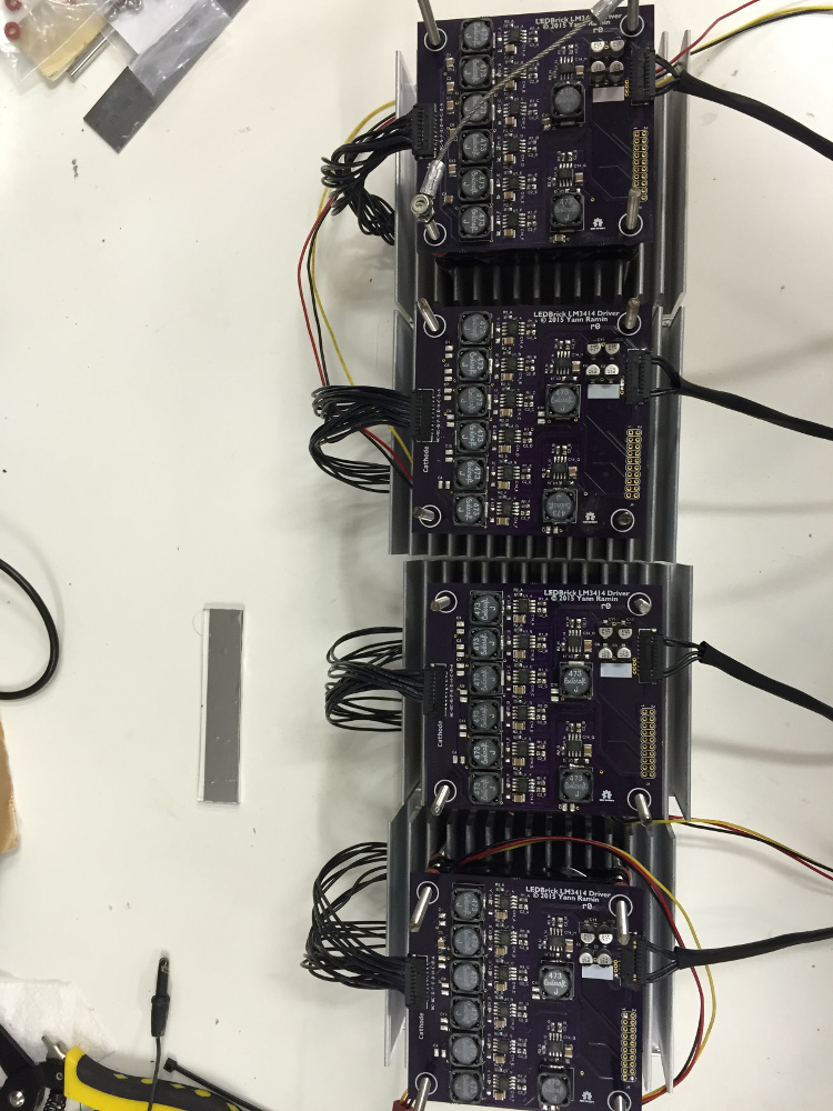
All connectors to the board are a series of Molex PicoLock blade-style high current flat wire-to-board connectors.
 
Last edited:
OP
OP
theatrus

theatrus

Valuable Member
View Badges
Joined
Mar 26, 2016
Messages
1,957
Reaction score
3,355
Location
Sacramento, CA area
Rating - 0%
0   0   0
Here were the first versions of the emitter board, still in use today:

ledbrick-board-1.jpg


I drilled and tapped all the M4 screws into the heatsink via a small drill press and a hand tap:

board-heatsink-2.jpg


Next up was placing and soldering the LEDs.

I used a Kapton stencil from OSHStencil (about $10) and solder paste:

01.jpg


Placing parts on to the PCB (via tweezers, on to the solder paste)

02.jpg


Back then I was using a Hamilton Beach Skillet to re-flow the solder paste - works a treat for single sided boards.

03.jpg


Success! I'm going to skip most of the test pictures, but I tested each channel. This is the Violet channel (Rebel UV):

05.jpg
 
OP
OP
theatrus

theatrus

Valuable Member
View Badges
Joined
Mar 26, 2016
Messages
1,957
Reaction score
3,355
Location
Sacramento, CA area
Rating - 0%
0   0   0
During this phase of the project, I did a lot of testing for thermal (how hot it got), and power output. Here is a shot of the unit getting a PAR reading at a mere 6 inches.

01.jpg


I also grabbed thermal images of the board operating with three channels at 750mA, and no fan.

FLIR0029.jpg


A large part of this project was all the mounting holes aligning to an 80mm fan footprint, so I could use threaded rods from top to bottom as the structural members. Since there was no way to get 8 LDD drivers (for 8 channels) into the footprint I wanted, I started with my own driver layout based on 8 LM3414 ICs on a single board:

driver1.png


i.png


The board has a 20pin stacking connector to break out the PWM signals to an auxiliary board.

Here is a unit undergoing initial testing - it was built via the same exact paste + skillet reflow method.

build1-sm.jpg


The various schematics, board files and BOMs are available on my GitHub account:

https://github.com/theatrus/ledbrick
 
OP
OP
theatrus

theatrus

Valuable Member
View Badges
Joined
Mar 26, 2016
Messages
1,957
Reaction score
3,355
Location
Sacramento, CA area
Rating - 0%
0   0   0
Here are all 8 channels fully connectered and crimped:

full-driver-hookup.jpg


The current for all the channels at this point was set to 500mA - the limit of the two blue and white channels has been raised to 800mA in a later modification (its a single resistor swap):

all-lit.jpg


power-supply-50w.jpg


As for the mechanics, time to start building the stack:

m3.jpg

m2.jpg

three.jpg

f1.jpg
 
OP
OP
theatrus

theatrus

Valuable Member
View Badges
Joined
Mar 26, 2016
Messages
1,957
Reaction score
3,355
Location
Sacramento, CA area
Rating - 0%
0   0   0
The wire is to act as the final hanger.

Now, we need a way to control everything!

This took several revisions to get right, but the idea was to use a Bluetooth LE link back to a Raspberry Pi to set each channel, unit, and do local monitoring of temperature and fan control.

board2d.png


This design... had issues, wrong connectors, etc, so took a Rev 2

050a718b72e049e6fccfb4dbcf73fda3.png


The overall features of the controller:

Features:

- 8 PWM channel dimming (though 16 total could be brought out to a header)
- 24V power input
- 12V fan power output with voltage control, PWM control, and tachometer readback
- nRF51 based Cortex-M0 + Bluetooth Low Energy stack (phone or PC control and monitoring of each channel and fan)

Here is a shoddy reflow job (the capacitors are all crooked, oops), but it does work!

ble1.jpg


Initial testing was based on Nordic's "template" code example for a BLE Peripheral, and a Mac with LightBlue.

two_char.png


More units built, all of these are in "production" so to speak today over my 90 gallon

87c424400b9e4feab62b5fe323f37db7.jpg
 
OP
OP
theatrus

theatrus

Valuable Member
View Badges
Joined
Mar 26, 2016
Messages
1,957
Reaction score
3,355
Location
Sacramento, CA area
Rating - 0%
0   0   0
Still missing from the equation is an outside case!

I decided to do a laser-cut acrylic case, borrowing some time on a shop cutter. Here are the top and bottom panels:

cutting.jpg

after_cut2.jpg


Here are the first revision side panels - way too many holes to make the fan useful:

glue1.jpg


finish3.jpg


I made an internal fan shroud to avoid air re-circulation:

fan_shroud1.jpg


And then I re-designed the side panel with a neat wave :)

new_box.jpg


I ended up running the units in the garage for several weeks before installing them:

hanging.jpg


And finally, a terrible picture of them installed:

installed.jpg


All running under control from a Raspberry Pi over Bluetooth:

screen.png
 

TheEngineer

Formerly icecool2
View Badges
Joined
Nov 26, 2011
Messages
7,296
Reaction score
7,695
Location
PA
Rating - 0%
0   0   0
Nice job. Always a plus when you have access to equipment for your DIY project :). Where do you have the boards made?
 
OP
OP
theatrus

theatrus

Valuable Member
View Badges
Joined
Mar 26, 2016
Messages
1,957
Reaction score
3,355
Location
Sacramento, CA area
Rating - 0%
0   0   0
Did OSHPark take over from batchpcb?


More or less yeah. It's been reliable for me over the past couple of years and a lot faster than batchpcb.

You can always price at pcbshopper.com - there is dirtypcbs which is the super cheap option, and cheap but better producers like pcbway that I'm now using for my metal PCB 8 or 16 Up single reflector Luxeon Z build.

Pics soon.
 
OP
OP
theatrus

theatrus

Valuable Member
View Badges
Joined
Mar 26, 2016
Messages
1,957
Reaction score
3,355
Location
Sacramento, CA area
Rating - 0%
0   0   0
Due to some community prompting, I'm working on a quick driver design based on the RichTek RT8471, which is a standard 1A constant current buck converter at a very low price (50 cents if you buy 10 on digikey).

The first thing is to build a calculator sheet for the actual parameters from the RT8471 datasheet to validate choice of inductors:

https://docs.google.com/spreadsheets/d/1bYPY4P0Mx01CxyV_Ji7G9NawRCKehLjmNI9j9Z-l8ZI/edit#gid=0

The schematic is fairly standard:

schematic.png


Start by laying out one channel:

basic-channel.png


Things to watch for:

- A lot of switching current moves between the diode, inductor, Vcc, and SW->Gnd nodes. These need to be connected with lots of copper and kept very close, lest the PCB traces act as unwanted inductors and radiators.
- Pick an inductor with a suitable saturation current (ISat).
- Pick a diode which can handle about 2x the steady state current, or one rated for pulse currents - when the switch is off, a large current spike travels through this diode back to the Vcc rail, especially at lower duty cycles (lower Vout vs Vin). The voltage rating must be higher by some margin over the maximum VIn.

Here is the first shot at the 1.5inch x 2 inch board with 4 channels:

basic-4channel-board.png


Not counting the PCB, building two of these boards would cost you about $25 (for 8 channels across two boards, with 0-2 spare parts per channel).

http://www.digikey.com/short/3jw3rt

Note that I haven't built this yet, so needs verification. Stay tuned! :)
 
OP
OP
theatrus

theatrus

Valuable Member
View Badges
Joined
Mar 26, 2016
Messages
1,957
Reaction score
3,355
Location
Sacramento, CA area
Rating - 0%
0   0   0
I've also been messing around with using Luxeon Z 3W emitters on a single star board to get "as good as possible" light mixing.

build-7.jpg


These are a radial pattern, so each LED has a pie-shaped copper pour to control thermals. The board is from PCBWay, and I made it mount a Ledil Brooke Wide reflector. I made a two and four channel prototype. I used push-in terminal blocks for an easy wiring setup, unlike my last connector approach (which was nice, but a pain to hand-crimp connectors for).

The two channel:
build-5.jpg


I also experimented using a sheet of Satin Ice 89% transmissive acrylic diffuser on top of the reflector:

diffuser1.jpg


build-6.jpg


- Spread and diffuse light without any reflector mounted (A+) - the thin object in front of the light test does show multiple colored shadows in air. Much less scattering than other builds I've done with widely spaced LEDs.
- With the reflector alone, there is a color speckling if you look at a white surface - some areas have a more dominant tone than others. This is again in air, need to test with water.
- With the diffuser plate mounted, by far the softest light, with a marked increase in intensity from the un-reflectored lights.

As for PAR, using the SQ-500 sensor from Apogee (which reads blue LEDs lower than an SQ-120 sensor head)

230 naked LEDs
460 with reflector + diffuser
830 with reflector
 
OP
OP
theatrus

theatrus

Valuable Member
View Badges
Joined
Mar 26, 2016
Messages
1,957
Reaction score
3,355
Location
Sacramento, CA area
Rating - 0%
0   0   0
Spent some time cleaning up the corner cases in the driver:

basic-4channel-board3.png


It fixed one major schematic error (where the recirculating diode connects - it wasn't on the switch node / LX pin), and added a <$1 micro controller - a PIC16F18323, which can drive the PWM pins and has a 0-10V input bank, along with an I2C bus header so you can daisy chain a bunch of these and control them all with an Arduino.

I put the updated schematics and output files on GitHub: https://github.com/blueacro/acroiq_drivers/tree/master/basic4
 
OP
OP
theatrus

theatrus

Valuable Member
View Badges
Joined
Mar 26, 2016
Messages
1,957
Reaction score
3,355
Location
Sacramento, CA area
Rating - 0%
0   0   0
I've been mucking with drivers and LEDs a bit more, so I'll share my "MicroDriver" concept:

micro-built.jpg


Its about 2.6x0.7inches long, runs on 12-48V, and can drive up to 1A per channel (based on the LM3414HV). Its also current adjustable from 400mA to 1A via the trim-pot on the board, while simultaneously being PWM dimmed (best of both worlds). I only put these together today so I haven't run the full gamut of testing.

The board on the left is my Bluetooth PWM controller prototype - more info soon ;)
 

Confuse

Active Member
View Badges
Joined
Aug 21, 2011
Messages
178
Reaction score
176
Location
Rancho Cucamonga, CA
Rating - 0%
0   0   0
Wow! Awesome work!

Just out of curiosity, could the Luxeon Z's be placed in a tighter array? Or does temperature become an issue? I have had a good experience with color blending on tighter arrays. One being the Nanobox, the other being Kessil, but I know Kessil is a dense matrix design of lower wattage LEDs, so I certainly don't expect to pack that many Z's together.

Also, what is your philosophy on LED spectrum? I'm a big fan of warm/neutral whites and "broader" spectrum LEDs that eliminate the need for red and green leds.
 

High pressure shells: Do you look for signs of stress in the invertebrates in your reef tank?

  • I regularly look for signs of invertebrate stress in my reef tank.

    Votes: 41 32.0%
  • I occasionally look for signs of invertebrate stress in my reef tank.

    Votes: 29 22.7%
  • I rarely look for signs of invertebrate stress in my reef tank.

    Votes: 25 19.5%
  • I never look for signs of invertebrate stress in my reef tank.

    Votes: 33 25.8%
  • Other.

    Votes: 0 0.0%
Back
Top