Profilux 4 - Inputs and Outputs

Users Who Are Viewing This Thread (Total: 1, Members: 0, Guests: 1)

MaddyP

'Til Reefdom Come...
View Badges
Joined
Jul 21, 2016
Messages
1,907
Reaction score
4,530
Location
Vancouver, WA
Rating - 0%
0   0   0
@Marco@GHLUSA
@Vinny@GHLUSA
@Matthias Gross

Does the Profilux 4 have the capability of reading a digital signal or a 0-10v signal from something like a continuous level sensor? I would like to control a modulating ball valve which would be controlled by 0-10V just like the Profilux Temperature Controller 2. But instead of relying on the temp probe for variation of the 0-10V signal, I need the system to rely on a digital input.
 

Gaël

Well-Known Member
View Badges
Joined
Sep 27, 2014
Messages
612
Reaction score
355
Location
France
Rating - 0%
0   0   0
PLM-ADIN card hase two 0-10v input.
But you can only monitor and get alarm.

For exemple i use it to monitor level of two my RO and saltwater tank with pressure sensors.
 

Lasse

10K Club member
View Badges
Joined
Mar 20, 2016
Messages
10,887
Reaction score
29,890
Location
Källarliden 14 D Bohus, Sweden
Rating - 0%
0   0   0
PLM-ADIN card hase two 0-10v input.
But you can only monitor and get alarm.

For exemple i use it to monitor level of two my RO and saltwater tank with pressure sensors.

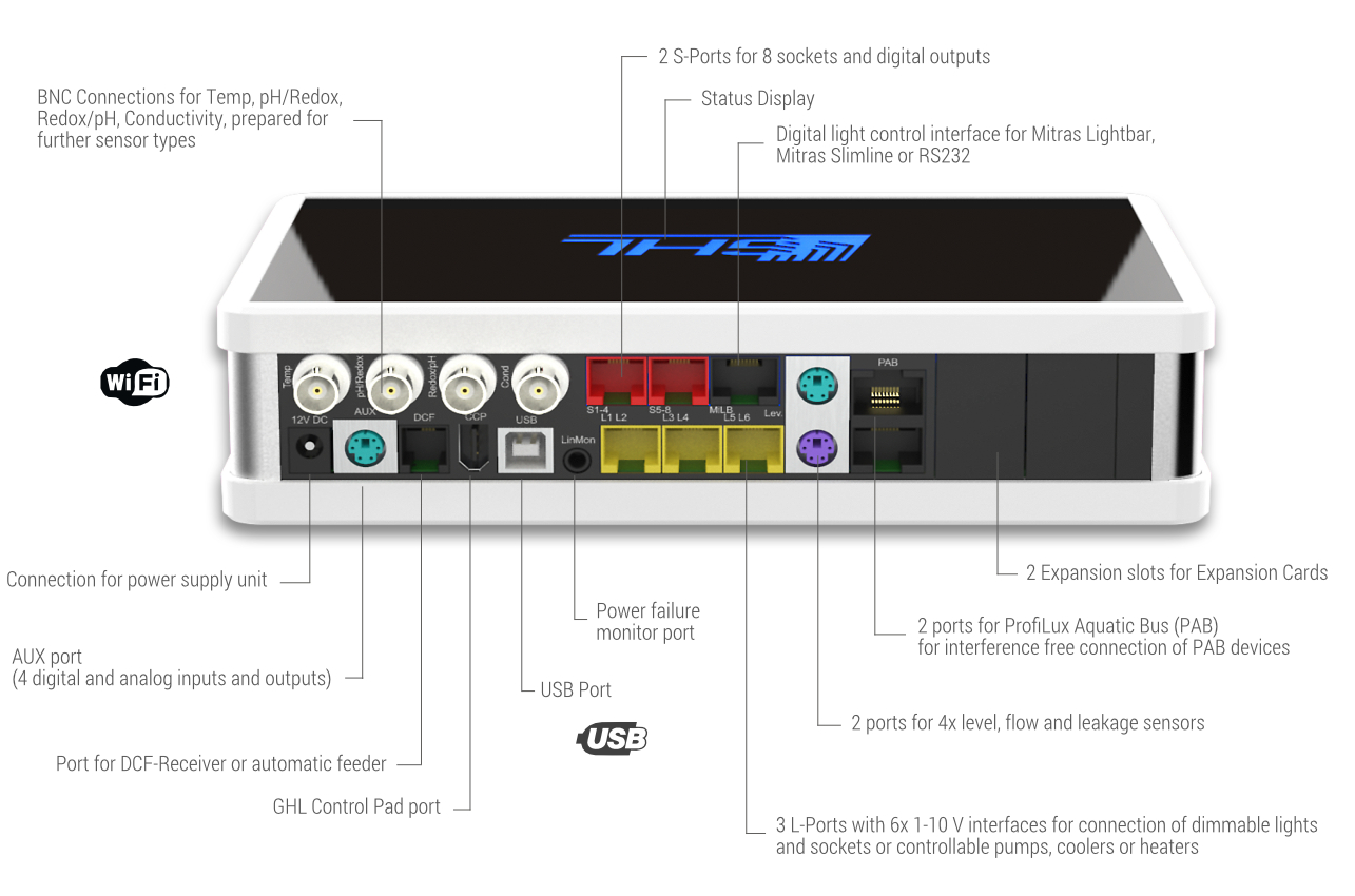
Or - see the AUX port

P4Anschl%C3%BCsse_Connections_E.jpg


Sincerely Lasse
 

Ditto

Valuable Member
View Badges
Joined
Apr 25, 2017
Messages
2,229
Reaction score
2,972
Location
Albany, NY
Rating - 0%
0   0   0
So the ball valave needs 0-10v to operate. So your saying it needs to be for example 8 volts all the time but needs to turn off because of x y or z?

Or is this a 3 way ball valve that 8 volts it output a 4 volts output b and 0 volts no flow?

What are you trying g to achieve with the ball valve?
 

Brew12

Electrical Gru
View Badges
Joined
Aug 14, 2016
Messages
22,488
Reaction score
61,035
Location
Decatur, AL
Rating - 0%
0   0   0
So the ball valave needs 0-10v to operate. So your saying it needs to be for example 8 volts all the time but needs to turn off because of x y or z?

Or is this a 3 way ball valve that 8 volts it output a 4 volts output b and 0 volts no flow?

What are you trying g to achieve with the ball valve?
I'm assuming that it is a variable position ball valve. Very expensive for hobby use, but they are cool toys. The 0-10V output signal would correspond to 0-100% open.

I don't see any reason the Aux port for inputs and the L port for output wouldn't work but I've never tried it.
 
OP
OP
MaddyP

MaddyP

'Til Reefdom Come...
View Badges
Joined
Jul 21, 2016
Messages
1,907
Reaction score
4,530
Location
Vancouver, WA
Rating - 0%
0   0   0
I'm assuming that it is a variable position ball valve. Very expensive for hobby use, but they are cool toys. The 0-10V output signal would correspond to 0-100% open.

I don't see any reason the Aux port for inputs and the L port for output wouldn't work but I've never tried it.
Yes, this will be a variable position ball valve. Absolutely expensive for hobby use, but the most bulletproof solution for my application.

I think my concern is more on the side of whether the Profilux is capable of the programming. I know it is capable or tyring a 0-10V output to the temp probe for continuous adjustment, but can this programming logic be applied to inputs other than temp?
 
OP
OP
MaddyP

MaddyP

'Til Reefdom Come...
View Badges
Joined
Jul 21, 2016
Messages
1,907
Reaction score
4,530
Location
Vancouver, WA
Rating - 0%
0   0   0
So the ball valave needs 0-10v to operate. So your saying it needs to be for example 8 volts all the time but needs to turn off because of x y or z?

Or is this a 3 way ball valve that 8 volts it output a 4 volts output b and 0 volts no flow?

What are you trying g to achieve with the ball valve?
The ball valve I've chosen to use actually has a smart actuator on it and will continuously adjust from 0-100% (fully open to fully closed) based on a 0-10V signal. I'll be using this valve to control a full siphon drain so as to balance the water level in the display continuously. It's a little odd, but I didn't want a standard overflow on my tank, this way all 4 sides will be unobstructed.

upload_2019-2-2_13-37-56-png.965586


upload_2019-2-2_13-38-21-png.965587


upload_2019-2-2_13-38-46-png.965588
 

Brew12

Electrical Gru
View Badges
Joined
Aug 14, 2016
Messages
22,488
Reaction score
61,035
Location
Decatur, AL
Rating - 0%
0   0   0
Yes, this will be a variable position ball valve. Absolutely expensive for hobby use, but the most bulletproof solution for my application.

I think my concern is more on the side of whether the Profilux is capable of the programming. I know it is capable or tyring a 0-10V output to the temp probe for continuous adjustment, but can this programming logic be applied to inputs other than temp?
I understand your concern.

If I understand correctly, you want to use an analog level instrument to read water level in your overflow box and report it to the Profilux as a 0-10V. You want to use this 0-10V input to control a proportional, or PI, controller to vary the o-10V output to the valve.
Level starts going up the valve opens a little more. Level starts dropping, valve closes a little more.

I'll do some digging but my gut feel is that cannot.
 
OP
OP
MaddyP

MaddyP

'Til Reefdom Come...
View Badges
Joined
Jul 21, 2016
Messages
1,907
Reaction score
4,530
Location
Vancouver, WA
Rating - 0%
0   0   0
I understand your concern.

If I understand correctly, you want to use an analog level instrument to read water level in your overflow box and report it to the Profilux as a 0-10V. You want to use this 0-10V input to control a proportional, or PI, controller to vary the o-10V output to the valve.
Level starts going up the valve opens a little more. Level starts dropping, valve closes a little more.

I'll do some digging but my gut feel is that cannot.
Hmm...almost. I want the GHL to read the value of a water level sensor (analog, 0-10V, or 4-20ma - whichever the GHL can read) and then utilize the same programming function used on the Profilux Temp Controller 2, varying the 0-10V output to keep as close to the set point as possible. Make sense?
 

Brew12

Electrical Gru
View Badges
Joined
Aug 14, 2016
Messages
22,488
Reaction score
61,035
Location
Decatur, AL
Rating - 0%
0   0   0
Hmm...almost. I want the GHL to read the value of a water level sensor (analog, 0-10V, or 4-20ma - whichever the GHL can read) and then utilize the same programming function used on the Profilux Temp Controller 2, varying the 0-10V output to keep as close to the set point as possible. Make sense?
Yup, makes sense. I'm guessing the Profilux Temp Controller 2 uses either PI or PID controls. In my industrial automation days I preferred PI for flow but PID did have value in temperature controls.
 
OP
OP
MaddyP

MaddyP

'Til Reefdom Come...
View Badges
Joined
Jul 21, 2016
Messages
1,907
Reaction score
4,530
Location
Vancouver, WA
Rating - 0%
0   0   0
Yup, makes sense. I'm guessing the Profilux Temp Controller 2 uses either PI or PID controls. In my industrial automation days I preferred PI for flow but PID did have value in temperature controls.
Ha! I knew there was a term for this I was forgetting. Yes, PID control, though it wouldn't need to be as precise, the level is going to vary somewhat.
 

Brew12

Electrical Gru
View Badges
Joined
Aug 14, 2016
Messages
22,488
Reaction score
61,035
Location
Decatur, AL
Rating - 0%
0   0   0
Ha! I knew there was a term for this I was forgetting. Yes, PID control, though it wouldn't need to be as precise, the level is going to vary somewhat.
Normally, the precision of a PID controller is established by adjusting the gain used as an input. I won't have time to dig into this tonight (my wife MAY not understand ;)) but I should have time this weekend. I don't know why it wouldn't be possible to use a 0-10V input, trick the controller into thinking it was temperature, and use the controller output to operate the valve.
 

Lasse

10K Club member
View Badges
Joined
Mar 20, 2016
Messages
10,887
Reaction score
29,890
Location
Källarliden 14 D Bohus, Sweden
Rating - 0%
0   0   0
Yup, makes sense. I'm guessing the Profilux Temp Controller 2 uses either PI or PID controls. In my industrial automation days I preferred PI for flow but PID did have value in temperature controls.

No - not that type that you are used of (I know what you mean because I have use PID too :). GHL have some options for the controller - you can chose by your self. The normal is on - of with hysteresis. The others are pulse stable - paus stable; pulse variable - paus stable and pulse stable - paus variable. In the two modes that´s alike PI and PID they use your hysteresis in order to manage the pulse. If you are outside your Hysteresis - the whole adjustable period is used - if you are inside - the computer adjust the time it is pulse or paus depended of the distance to the nominal value. Its rather good for both fast reactions and when it is taken time before you can counter read a change.


I´m not sure that you - without a special card can take in an 1-10 V signal from a pressure depended level indicator and reuse it for an outgoing 1-10 V signal - but I´m sure that with help of a normal float indicator, a 12 or 24 V DC motorized ball valve with 2 or 3 lines in, a switching relay and use of a timer function (using pulse function) and some PL 8Programing Locic - GHL programming language) is possible to solve the problem. One backslash with this solution is that the ball valve will work with small changes for the whole time and it can be some problems after a shout down.

But I hope that you will not have this solution in overflow box and not in the DT. Because if you place it in the DT it can go terrible wrong

Sincerly Lasse
 
Last edited:
OP
OP
MaddyP

MaddyP

'Til Reefdom Come...
View Badges
Joined
Jul 21, 2016
Messages
1,907
Reaction score
4,530
Location
Vancouver, WA
Rating - 0%
0   0   0
No - not that type that you are used of (I know what you mean because I have use PID too :). GHL have some options for the controller - you can chose by your self. The normal is on - of with hysteresis. The others are pulse stable - paus stable; pulse variable - paus stable and pulse stable - paus variable. In the two modes that´s alike PI and PID they use your hysteresis in order to manage the pulse. If you are outside your Hysteresis - the whole adjustable period is used - if you are inside - the computer adjust the time it is pulse or paus depended of the distance to the nominal value. Its rather good for both fast reactions and when it is taken time before you can counter read a change.


I´m not sure that you - without a special card can take in an 1-10 V signal from a pressure depended level indicator and reuse it for an outgoing 1-10 V signal - but I´m sure that with help of a normal float indicator, a 12 or 24 V DC motorized ball valve with 2 or 3 lines in, a switching relay and use of a timer function (using pulse function) and some PL 8Programing Locic - GHL programming language) is possible to solve the problem. One backslash with this solution is that the ball valve will work with small changes for the whole time and it can be some problems after a shout down.

But I hope that you will not have this solution in overflow box and not in the DT. Because if you place it in the DT it can go terrible wrong

Sincerly Lasse
I don't need to reuse a signal. Consider the level sensor and the ball valve separate. GHL takes in a value from the level sensor through one input and then through another output adjusts the ball valve accordingly. It might help if we were to think of the level sensor as a level probe, continuously changing based on the level of water. I need the ball valve to adjust based on deviation from set point.

No, this will not be plumbed to a overflow box. Plumbing comes straight out of the bottom of the display. This valve has a failsafe so that if it looses signal or power, it will close 100%. Considering this is an industry level solution, I feel confident it can be relied upon in case of power failure.
 

Lasse

10K Club member
View Badges
Joined
Mar 20, 2016
Messages
10,887
Reaction score
29,890
Location
Källarliden 14 D Bohus, Sweden
Rating - 0%
0   0   0
I don't need to reuse a signal.

You use the input signal to produce a new output signal from the GHL - that´s I meant with reuse.

Plumbing comes straight out of the bottom of the display. This valve has a failsafe so that if it looses signal or power, it will close 100%. Considering this is an industry level solution,

Whats happen if only the regulating ball valve lose signal (or power) and close but the returnpump still working? Whats happen if the levelindicator gives a wrong signal? whats happen if you get a leak below the aquarium but before the valve? I have been working with industry level equipment all my life in pumpstations and so one - Learned one thing - it is not a question if a mechanical equipment will be broken - it is a question of when! And put in elcronics in that equation too ..... IMO -
you ask for trouble.

Sincerely Lasse
 
OP
OP
MaddyP

MaddyP

'Til Reefdom Come...
View Badges
Joined
Jul 21, 2016
Messages
1,907
Reaction score
4,530
Location
Vancouver, WA
Rating - 0%
0   0   0
You use the input signal to produce a new output signal from the GHL - that´s I meant with reuse.


Whats happen if only the regulating ball valve lose signal (or power) and close but the returnpump still working? Whats happen if the levelindicator gives a wrong signal? whats happen if you get a leak below the aquarium but before the valve? I have been working with industry level equipment all my life in pumpstations and so one - Learned one thing - it is not a question if a mechanical equipment will be broken - it is a question of when! And put in elcronics in that equation too ..... IMO -
you ask for trouble.

Sincerely Lasse

You may well be right, but lets see if I covered all my bases:

Problem = Result
Loss of 1-10V Signal = Valve Closes 100%, Pumps start drawing air (display will hold return section volume without overflowing)
Loss of 110V Power = Valve Closes 100%, check valves in return lines close
Leak from bulkheads = Water drips back into sump
Valve closes while pumps are on = Pumps start drawing air (display will hold return section volume without overflowing)
Pump 1 fails = Valve compensates, check valve closes on return line
Pump 2 fails = Valve compensates, check valve closes on return line
Level sensor fails HIGH= Pumps start drawing air (display will hold return section volume without overflowing), emergency float (low) triggers with alarm
Level sensor fails LOW = Emergency float (HIGH) triggers and valve closes 100%
Valve fails open = Emergency float (HIGH 2) triggers and pumps turn on 100% with alarm
Valve fails closed = Pumps start drawing air (display will hold return section volume without overflowing), emergency float (low) triggers with alarm

Based on this, the only way for the display to drain completely would be if the valve failed open and both HIGH floats failed at the same time. If I have missed something, please let me know.
 
Last edited:

Lasse

10K Club member
View Badges
Joined
Mar 20, 2016
Messages
10,887
Reaction score
29,890
Location
Källarliden 14 D Bohus, Sweden
Rating - 0%
0   0   0
First - your two return pumps - you will rely on check valves. Check valves should not be used because of low water height (weak function) and they will sooner or later leak in a biological loaded salt water even with check valves with mechanical closing.

Second - which type of continuous level meter do you intend to use. My experiences with these type of level meters is that they are not as exact enough in order to regulate the level in a steady mode.

A ball valve is very difficult to adjust exactly - even if it is motorized. There is one weak point in their construction too. The shaft between the ball and the motor is usually sealed with an O-ring into the goods. This work very well if the valve only is used as fully open/closed but I have more than once get leaks in this O-ring when I have used this type of valves as flow regulators – even in cases where I have regulated very seldom – and you can risk the same conclusion as

Leak from bulkheads = Water drips back into sump
Sump must be a little larger than DT!

I may sound grumpy – but whole my body screams – No

Now to the main question – can you manage this with a P4? Probably there is a way but not an obvious one (for me)


Sincerely Lasse
 
OP
OP
MaddyP

MaddyP

'Til Reefdom Come...
View Badges
Joined
Jul 21, 2016
Messages
1,907
Reaction score
4,530
Location
Vancouver, WA
Rating - 0%
0   0   0
First - your two return pumps - you will rely on check valves. Check valves should not be used because of low water height (weak function) and they will sooner or later leak in a biological loaded salt water even with check valves with mechanical closing.

Second - which type of continuous level meter do you intend to use. My experiences with these type of level meters is that they are not as exact enough in order to regulate the level in a steady mode.

A ball valve is very difficult to adjust exactly - even if it is motorized. There is one weak point in their construction too. The shaft between the ball and the motor is usually sealed with an O-ring into the goods. This work very well if the valve only is used as fully open/closed but I have more than once get leaks in this O-ring when I have used this type of valves as flow regulators – even in cases where I have regulated very seldom – and you can risk the same conclusion as

Sump must be a little larger than DT!

I may sound grumpy – but whole my body screams – No

Now to the main question – can you manage this with a P4? Probably there is a way but not an obvious one (for me)


Sincerely Lasse
@Lasse I really appreciate your feedback. I’m sure there are several points of failure in everyone’s setup. And yes, this will have more than most. But I’m curious to see if it can be done and want to do something different. At the worst, I’ll have some water on the floor. Luckily it’s only a 12g tank. ;)
 

Lasse

10K Club member
View Badges
Joined
Mar 20, 2016
Messages
10,887
Reaction score
29,890
Location
Källarliden 14 D Bohus, Sweden
Rating - 0%
0   0   0
@Lasse I really appreciate your feedback. I’m sure there are several points of failure in everyone’s setup. And yes, this will have more than most. But I’m curious to see if it can be done and want to do something different. At the worst, I’ll have some water on the floor. Luckily it’s only a 12g tank. ;)

Come back when it failed - just to give me the reason to say - what did I say :) :)

But I understand the feeling - when someone says - it can´t be done - it triggers some rebellion force in my body – but this example – I would not dare :)

Sincerely Lasse
 

Creating a strong bulwark: Did you consider floor support for your reef tank?

  • I put a major focus on floor support.

    Votes: 54 40.3%
  • I put minimal focus on floor support.

    Votes: 28 20.9%
  • I put no focus on floor support.

    Votes: 48 35.8%
  • Other.

    Votes: 4 3.0%
Back
Top