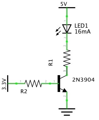
So i will not be doing this just because dimming 40% where my lights run to 10% is not really worth the effort. Maybe someday I will look into building my own LED's but for now the built in timer is fine. But if you decide to do this, and someone correct me if I am wrong I would not advise running it directly off the GPIO pin. I would use the following:
The PWM GPIO signal out would go in the 3.3v side with a square wave. Use the buck converter you linked above dialed down to 3.3.volts to supply the upper pictured voltage. D1 would be the OR light controller or where the black wire would connect. The key is to find out what the current draw is so that you can size the transistor and resistor appropriately. If you use the built in OR timers all you need to do is hijack the black wire and run ground from your pi build spliced into the red ground wire of the OR fixture.
If your your lights are anything like mine the clock sucks and never keeps time perfectly. So if you wanted to use the built in timers your brightness level and timer will over time be mismatched. To fix this disconnect the plug on the light. The purple and blue would need to be on a 12 volt relay timer programmed to come on and off at your set times with reef pi. The black wire would go to the same input on the transistor above and the red wire would go to your common ground. Since your clock is the same on both power and dimming you would be matched. Here is more on the OR light using the same basic concept.